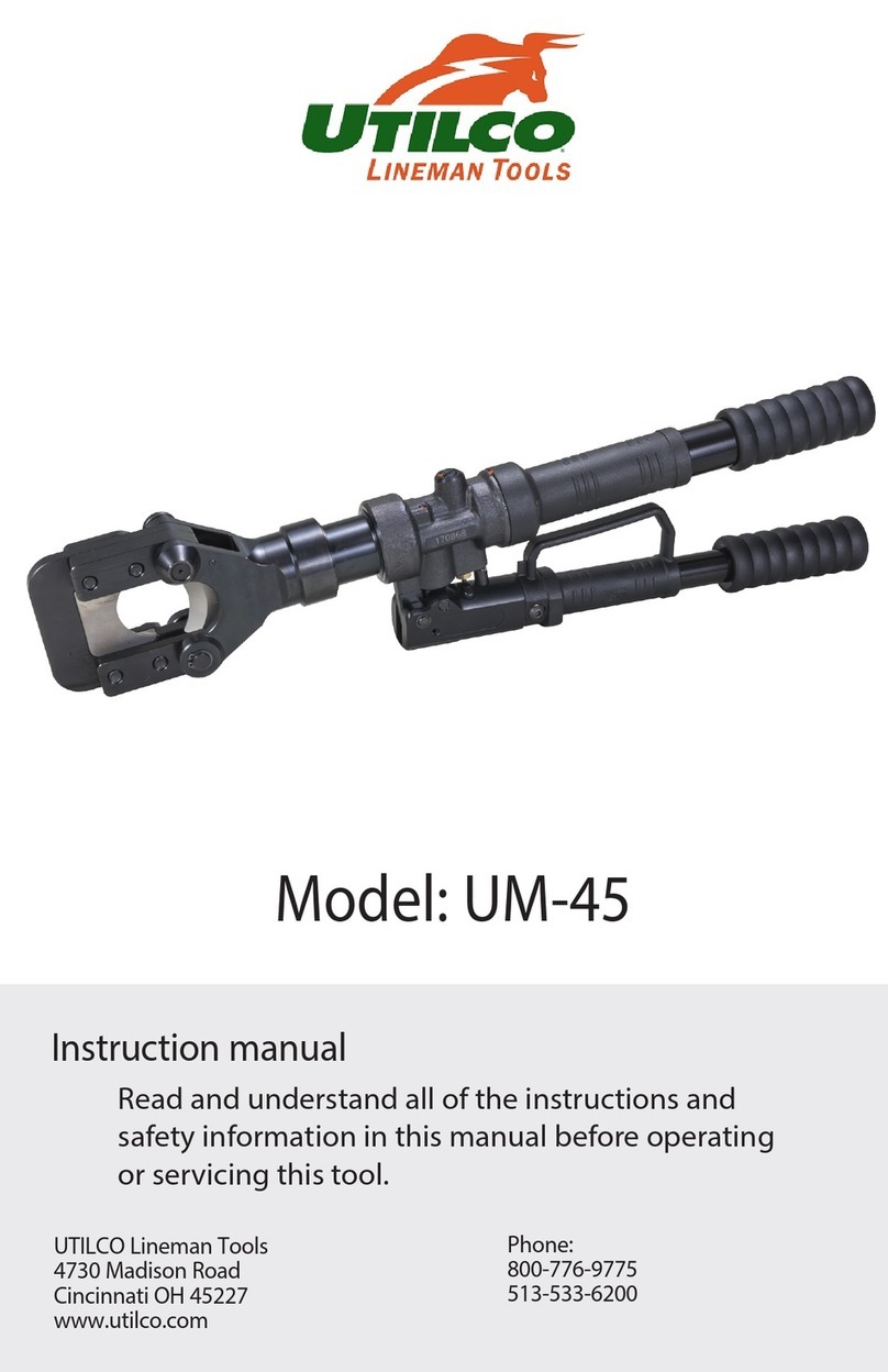
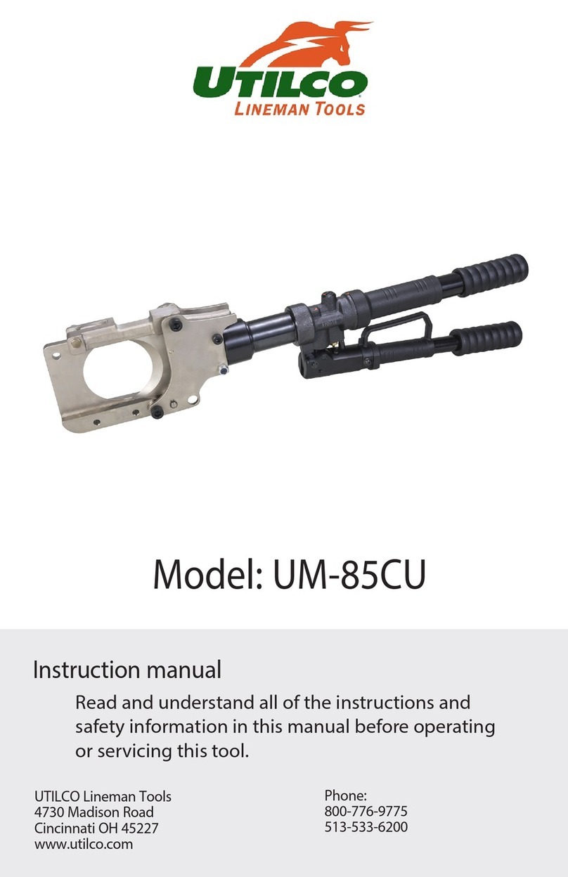
UTILCO UM-25 User manual

Instruction manual
Model: UM-25
Read and understand all of the instructions and
safety information in this manual before operating
or servicing this tool.
UTILCO Lineman Tools
4730 Madison Road
Cincinnati OH 45227
www.utilco.com
Phone:
800-776-9775
513-533-6200

Pg. 2
UM-25
Table of Contents
1.
Warranty and Servicing/Safety Symbols Page 3
2.
General Safety Information Page 4
3.
Technical Specications Page 5
4.
Tool Parts Labeled Page 6
5. Operating Instructions Page 7-8
6.
Tool Maintenance Page 9
7.
Tool Parts Breakdown Page 10
8.
Parts List Page 11
9.
Head Assembly Breakdown Page 12
10.
Parts List Page 13
THANK YOU...
for buying a UTILCO Lineman Tool. Our mission is to bring product innovation and exceptional
customer service to the marketplace. This tool line is reliable, dependable, and durable for our
customer’s needs.
Please read this instruction manual carefully before using the product. If you have any questions
about our product please reach out to our customer service department (see back cover). No part
of the contents of this manual may be reproduced, transmitted or circulated in any form or by any
means without the prior written authorization of UTILCO Lineman Tools.

Pg. 3
UM-25
Description of Safety Symbols:
Do not dispose
of product.
Please recycle
Electric Shock
Hazard- use
proper protective
equipment
Attention!
Risk of
cutting injury
Never use
with unlocked
workhead
Read the operating
instructions
before use
Wear protective
goggles
1. Warranty and Servicing
UtilPro™ 5-Year Tool Service Protection Program
Introducing the industry’s best service & support program for all your UTILCO hydraulic crimping
and cutting tools. All UTILCO tool buyers are automatically registered in the UtilPro Service
Protection Program and will receive free tool repairs for defects in material or workmanship on their
tool(s) for ve years after their original purchase date. (Excludes abuse, non-intended use, tampered
with or normal wear and tear.)
UtilPro Tool 5 Day Repair Pledge
If your tool(s) need repair at any time within ve years of your original purchase date, our UtilPro
service network will repair your registered tools within ve business days of receipt.
UtilPro Tool Loaner Program
If you need a replacement tool during any repair, our UtilPro network can typically provide a
comparable loaner tool to registered tool owners while your tool is being repaired.
FREE Tool Reconditioning
Your rst reconditioning is on us!
To Find a UtilPro Service Partner
Call UTILCO for assistance in solving tool performance issues or for any of your service needs.
UTILCO tool owners will be oered options to solve any tool replacement, parts or repair
issues.
Call 513-533-6200 or 800-776-9775
Monday to Friday
8:00AM to 5:00PM Eastern Time (ET)

Pg. 4
UM-25
2. General Safety Information
Read all safety warnings, instructions provided with this tool. Failure to follow all
instructions listed below may result in electric shock, re and/or serious injury. Save all
warnings and instructions for future reference.
WORK AREA SAFETY
• Keep work area clean and well lit. Cluttered or dark areas invite accidents.
• Keep children and bystanders away while operating a hydraulic tool. Distractions can
cause you to lose control.
PERSONAL SAFETY
• Stay alert, watch what you are doing and use common sense when operating a
hydraulic tool. Do not use a hydraulic tool while you are tired or under the inuence
of drugs, alcohol, or medication. A moment of inattention while using hydraulic tools
may result in serious personal injury.
• Use personal protective equipment. Always wear eye protection. Protective
equipment such as rubber gloves, non-skid safety shoes, hard hat or hearing
protection used for appropriate conditions will reduce personal injuries.
• Do not overreach. Keep proper footing and balance at all times. This enables better
control of the tool in unexpected situations.
• Do not let familiarity gained from frequent use of hydraulic tools allow you to
become complacent and ignore tool safety principles. A careless action can cause
severe injury within a fraction of a second.
SERVICE
• Have your tool serviced by a qualied repair person using only identical replacement
parts. This will ensure that the safety of the hydraulic tool is maintained.

Pg. 5
UM-25
3. Technical Specications
Force developed: 6.7 tons
Jaw opening: .98 in.
Hydraulic oil: Shell Tellus S2 V15
Dimensions: 15.5 in. x 2.1 in. x 6.5 in. (L x W x H)
Weight: 6.4 lbs
Cut Capacity
CU: .95 in.
AL: .95 in.
ACSR: 556
Guy wire: 5/8 in.
Guy wire (EHS): 1/2 in.
Ground rod: 5/8 in.
15.5 in. (394 mm)
6.5 in. (166 mm) 2.1 in.(54 mm)

Pg. 6
UM-25
Latch
Pump handle
Release handle
Serial number
4. Tool Parts Labeled
Advance mode
Retract mode
Movable blade
NOTE: Includes durable plastic carrying case.

Pg. 7
UM-25
5. Operating Instructions
Be sure to read instructions carefully, wear safety goggles, and keep ngers away from cutting
head.
ADVANCING & RETRACTING THE TOOL
1. To advance the tool, twist release handle to advance mode then lift and lower pump handle.
2. To retract the tool, twist release handle to retract mode and the blade will retract.
CUTTING
1. Retract the blade fully by by twisting the handle to retract mode.
2. Unlatch the tool head by pulling up on release lever.
3. Close head and latch around material. Be sure tool is completely latched or damage will occur.
4. Make sure all cuts are made perpendicular to the cutting head or damage will occur to blades.
Advance mode
Retract mode
Movable blade
CAUTION: always wear eye protection
while cutting
WARNING: Hardened material can y
when cutting. Always point away from
people or objects.

Pg. 8
UM-25
5. Advance the blade by twisting the release handle to advance mode, then lifting and lowering
pump handle.
6. Once cutting cycle is complete, rotate release handle to retract mode. The cutting blade will
release back to the starting position.
NOTE: Your tool is equipped with with a safety bypass. When maximum pressure is achieved,
you will hear a pop.

Pg. 9
UM-25
6. Tool Maintenance
Daily maintenance:
• After each cutting cycle wipe the cutting head jaws free of metal shavings.
• Wipe down all steel parts with WD-40.
• Store the tool in a non-humid environment.
The tool should provide many years of service when given the proper maintenance and care.
Should you experience any diculty with the operation and maintenance of this tool, contact our
customer service department (see back cover).

Pg. 10
UM-25
7
7. Tool Parts Breakdown
1
3
4
5
6
7
2
17
16
15
14
13
12
11
10
9
8
32
31
30
29
28
27
26
25
24
23
22
21
20
19
18
33 47
46
45
44
43
42
41
40
39
38
37
36
35
34
11
12
19
20
20
20
29
28 26
26
35
36
37
37
48

Pg. 11
UM-25
# Part Number Part Description Qty.
1 E712166 CUTTING HEAD MNT 1
2 104179 RETAINING RING 1
3 700225 MOVING BLADE 1
4 712008 STOP BUSHING 1
5 103545 COMPRESSION SPRING 1
6 700763 LOCKING PIN 1
7 712162 PISTON 1
8 760380 SUPPORT RING 1
9 760375 O-RING SEAL 1
10 712161 PISTON 1
11 710042 FOUR-LIPS SEAL 2
12 760383 SUPPORT RING 4
13 711971 SPRING BODY 1
14 102733 COMPRESSION SPRING 1
15 711968 SPRING PEN 1
16 714764 VALVE DISC 1
17 710828 O-RING SEAL 1
18 760212 GRIP PUMP LEVER MNT 1
19 760179 BOLT 2
20 205230 LOCKING RING 4
21 760205 PUMPING PISTON 1
22 713181 PISTON SCREW 1
23 200810 CAP SCREW 1
24 760238 ANCHOR SHORT 1
8. Parts List
# Part Number Part Description Qty.
25 712164 PUMP BODY 1
26 760415 BALL 6
27 760194 SPRING PEN 2
28 760232 SEAL DISC 3
29 760203 LOCK SCREW 3
30 760356 COMPRESSION SPRING 1
31 760346 DISC 1
32 760190 VALVE SCREW 1
33 706979 OIL SCREEN 2
34 713182 LIP SEAL 1
35 760186 PISTON 2
36 700732 O-RING SEAL 2
37 700665 COMPRESSION SPRING 5
38 710984 PRESSURE SPRING 1
39 200308 GRUB SCREW 1
40 760348 DISC 1
41 710344 VALVE BODY 1
42 713796 PRESSURE CONTROL VALVE 1
43 760182 TANK 1
44 760183 TANK PLUG 1
45 103573 O-RING SEAL 1
46 760184 BALL RACE 1
47 LABEL 1
48 760213 TANK GRIP MNT 1

Pg. 12
UM-25
9. Head Assembly Breakdown
1
7
10
8
9
6
5
4
3
2
1
7

Pg. 13
UM-25
# Part Number Part Description Qty
1 206028 HEXAGONAL NUT 8
2 700518 TREADED BOLT 4
3 700590 FRAME 1
4 700591 BLADE GUIDE 1
5 700761 COMPRESSION SPRING 1
6 700226 FIXED BLADE 1
7 701425 LOCKING RING 4
8 712010 BOLT 2
9 702021 LOCKING LEVER 1
10 712167 HEAD FORK 1
10. Parts List

Pg. 14
UM-25
Notes:

Pg. 15
UM-25
Notes:

Service:
Date: 07/17 Version 1
UTILCO Lineman Tools
4730 Madison Rd.
Cincinnati, OH 45227
Phone: 800-776-9775
513-533-6200
www.utilco.com
Table of contents
Other UTILCO Cutter manuals
Popular Cutter manuals by other brands

Leister
Leister 143.830 operating instructions

Tar River
Tar River ERC Series Operator's manual

EFA
EFA Z28S Operating Instructions, Maintenance instructions, Spare Part List

Gastrodomus
Gastrodomus TA25K Installation, use and maintenance

Logan Graphic Products
Logan Graphic Products 545 instruction manual

SIZZIX
SIZZIX eclips2 user guide