Utilitech CZQTV5MLSCN User manual

1
ITEM #1048297
CEILING-MOUNT
DUAL QUARTZ HEATER
MODEL #CZQTV5MLSCN
SERIAL NUMBER ______________________________
SM21115
PURCHASE DATE ________________________________
QUESTIONS, PROBLEMS, MISSING PARTS? Before returning to your retailer, call our customer service
department at 1-866-994-4148, 8 a.m. - 8 p.m., EST, Monday - Sunday.
UTILITECH and logo design are trademarks or
registered trademarks of LF, LLC. All rights reserved.

2
TABLE OF CONTENTS
PRODUCT FEATURES & SPECIFICATIONS
SAFETY INFORMATION
ProductFeatures&Specications.............................................................................................................. 2
Safety Information................................................................................................................................. 2 – 3
Installation Instructions ....................................................................................................................... 4 – 5
Operating Instructions ................................................................................................................................ 6
Care and Maintenance ............................................................................................................................... 7
Warranty .................................................................................................................................................... 7
PLEASE READ AND UNDERSTAND THIS ENTIRE MANUAL BEFORE ATTEMPTING TO ASSEMBLE, OPERATE
OR INSTALL THE PRODUCT.
PRECAUTIONS:
Thisproductisintendedforindoorresidentialandofceuseonly,notforindustrialorothercommercialapplication.
Use only with electrical wiring that is in good working order and that meets applicable codes and ordinances. This
heater must be plugged in to a 120V AC, 15 A (or larger) circuit. Do not plug anything additional into the same circuit.
Ifyouhaveanyquestionswhetheryourwiringisadequate,consultaqualiedelectrician.Riskofre,overheating,
malfunction, property damage, injury or even death may result if not adhered to.
Use your heater only with a working smoke detector located in the vicinity of your heater.
While using your heater, you should follow the IMPORTANT INSTRUCTIONS listed below.
As part of those instructions, we have used the word “WARNING” to indicate the level of hazard.
WARNING indicates a hazard which, if not avoided, could result in injury or death.
Whenusingelectricalappliances,basicprecautionsshouldalwaysbefollowedtoreducetheriskofre,electricshock
and injury to persons, including the following important instructions.
IMPORTANT SAFETY FEATURES
*POWER INDICATOR LIGHT:
The power indicator light, located near the control panel, lights whenever the heater is plugged in.
**AUTOMATIC OVERHEAT PROTECTION:
The heater is equipped with an automatic overheat protection device located inside the body of the heater. If the
heater grille is obstructed, or if the heater gets too hot for any reason, the automatic overheat protection device will
turn the heater off. To reset the heater, simply turn power off and unplug the heater for 10 minutes until it cools down
and you may plug in and restart the heater. Be sure that the heater is on a smooth level surface with no obstructions.
Top Mounted Control Panel
Power Indicator Light*
Safety Overheat Protection**
Stay cool body with dent-resistant end panels
Silent Operation
FEATURES
Two Heat Settings:
II – High 1500 watts (5120 BTU)
I – Low 750 watts
120V A.C.
60Hz
12.5A
SPECIFICATIONS
3
IMPORTANT INSTRUCTIONS:
SAFETY INFORMATION
• Do not touch body of heater when in use. This heater is hot when in use, to avoid burns, do not let bare skin touch
hot surfaces. If provided, use handles when moving this heater.
• Keep combustible materials, such as furniture, pillows, bedding, papers, clothes, and curtains at least 3 feet (0.9m)
from the front of the heater and keep them away from the sides and rear.
• Do not leave heater on unattended. Extreme caution is necessary when any heater is used by or near children or
invalids.
• Always unplug heater when not in use.
• Do not operate any heater with a damaged cord or plug or after the heater malfunctions, has been dropped or
damagedinanymanner.Returnheatertoourcustomerservicedept.forexamination,electricalormechanical
adjustment,orrepair.(Seethesection“ForRepairs”onlater).
• Do not use outdoors.
• Use your heater only in dry environments. This heater is not intended for use in a bathroom, laundry area, or similar
locations, or near sinks, washing machines, swimming pools or other sources of water. Never locate heater where it
may fall into a bathtub or other water container. Do not use heater outdoors.
• Donotuseindampenvironmentssuchasoodedbasements.
• Do not run cord under carpeting. Do not cover cord with throw rugs, runners, or the like. Arrange cord away from
trafcareaandwhereitwillnotbetrippedover.
• To disconnect heater, turn controls to off, then remove plug from outlet.
• Connect to properly grounded outlet only.
• Do not insert or allow foreign objects to enter any ventilation or exhaust opening as this may cause an electric shock
orreordamagetheheater.
• Aheaterhashotandarcingorsparkingpartsinside.Donotuseitinareaswheregasoline,paint,orammable
liquids are used or stored.
• Use this heater only as described in this manual. Any other use not recommended by the manufacturer may cause
re,electricshock,orinjurytopersons.
• Always plug heaters directly into a wall outlet/receptacle. Never use with an extension cord or relocatable power tap
(outlet/power strip).Always unplug heater/fan when not in use.
SAVE THESE INSTRUCTIONS
WARNING – FIRE HAZARD
Heaterhashotandarcingorsparkingpartsinside.Donotusenearcombustiblematerialsorammablegasesor
sourcesofheat.DONOTUSEinareaswheregasoline,paintorammablematerialsareusedorstored.Keep
combustible materials such as furniture, pillows, bedding, papers, clothes and curtains at least 3 feet (0.9 m) from the
frontoftheheaterandkeepthemawayfromthesidesandrear.Topreventapossiblere,donotblockairintakesor
exhaust in any manner. Do not insert or allow foreign objects to enter any ventilation or exhaust opening as this may
causeanelectricshock,re,ordamagetheheater.
WARNING – ELECTRICAL SHOCK HAZARD
Do not use with damaged cord or plug. Use with adequate electrical system that is up to code.
Do not operate any heater with a damaged cord or plug or after heater malfunctions, has been dropped or damaged
in any manner. Do not operate heater with a broken heating element or ceramic cone or any visual imperfections. For
repairs covered under warranty, see warranty statement. For all other repairs contact us at [email protected] or
visit www.lowespartsplus.com.
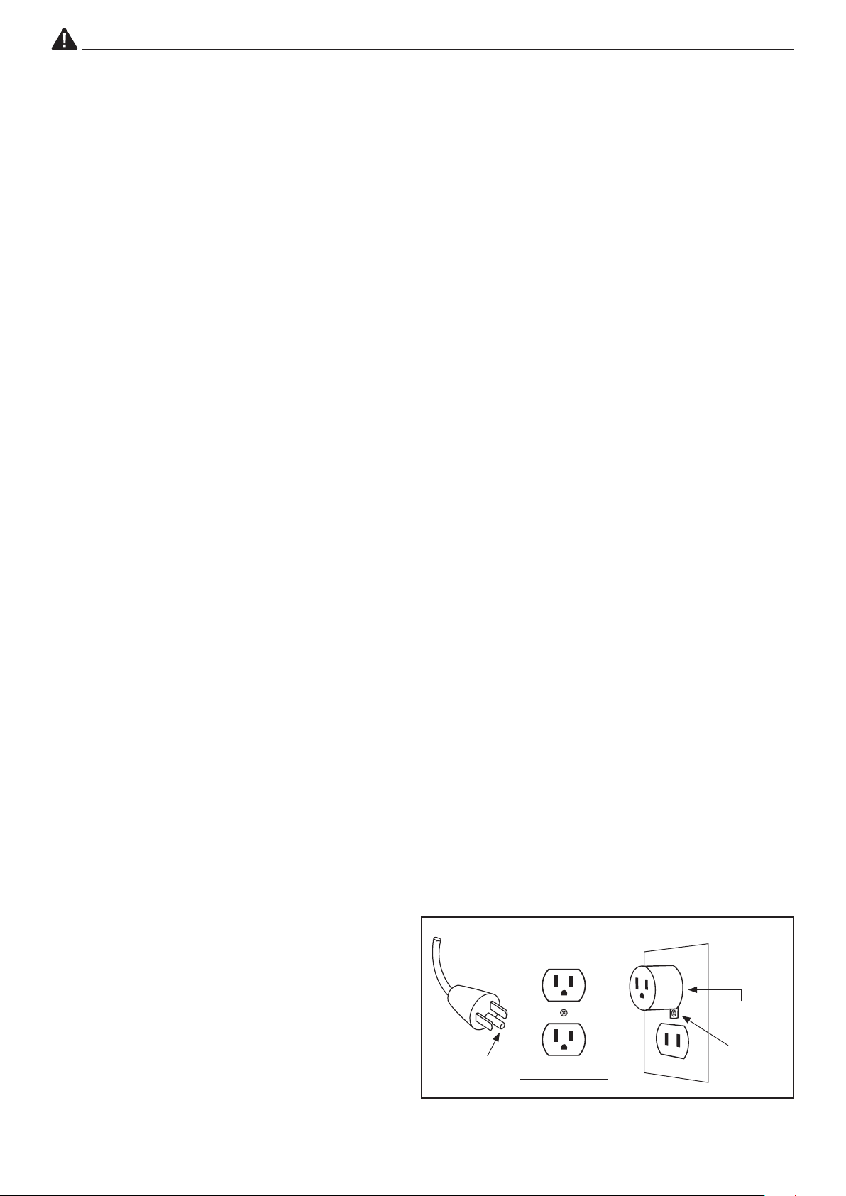
This heater is for use on 120 volts. The cord has a plug as shown at ''A'' in Figure below. An adapter as shown at
''B'' is available for connecting three-blade grounding type plugs to two-slot receptacles. The green grounding lug
extending from the adapter must be connected to a permanent ground such as a properly grounded outlet box. The
adapter should not be used if a three-slot grounded receptacle is available.
PET OWNERS NOTE:
The health of birds and some small pets
are extremely sensitive to the fumes
given off during the initial use of many
appliances. Although these fumes are not
harmful to humans, it is recommended that
this heater not be used around birds and
small pets during its initial use until the
manufacturing corrosion coatings burn off.
GROUNDING METHODS
GROUNDING
PIN
GROUNDING
ADAPTER
GREEN
GROUNDING
LUG
B
A

4
INSTALLATION INSTRUCTIONS
GETTING STARTED: FIRST CHOOSE A MOUNTING INSTALLATION OPTION.
WARNING:
This unit is intended for use ONLY as a ceiling mounted
heater. Mounting on a wall or sloping surface such as a
roofisariskofreduetopossibleoverheatingoftheunit
or igniting nearby combustible materials.
KEY SLOT OPTION:
1. Locate a desired position on your ceiling in the area to
be warmed. (Heater should be at least 3 feet (0.9m)
away from the nearest wall or other combustible
material)
2. The mounting bracket may be attached to a single
joist (Fig. A) or span across two joists (Fig. B) Failure
tomountheatertojoistscanresultininjuryandorre
hazards.
3. Ifyouareinstallingthebrackettoanunnishedceiling
withexposedjoists,proceedtostep4.Onanished
ceiling the joists are hidden behind the ceiling dry wall
or plaster. You must locate and mark the location of
the center of the joists in the mounting area. Joists are
typically 1-1/2 inch (38mm) wide and 16 inch (406mm)
or 18 inch (457mm) apart. They usually run parallel
withthenarrowdimensionoftheroom.A“StudFinder”
available at most hardware stores may help in locating
the center of these hidden joists.
4. Using the mounting bracket as a template, line up one of
the key slots at each end of the bracket with one or two
joists and mark the slotted openings. If you cannot line
up the holes in the bracket with the joists you will have to
use other mounting methods. See “Installing a Mounting
Board.”
5. Using a 1/8-inch (3.2mm) drill bit, drill a hole in the
center of each marked key slot. Install the two screws
provided leaving about 1/4 inch (6.4mm) between the
head of the screw and the mounting surface. Slip the
mounting bracket over the screw heads and slide the
bracket to engage the screws in the slots. Tighten
screws securely.
INSTALLING A MOUNTING BOARD (If required):
If your joists are more than 18 inch (457mm) apart, or
you have chosen to mount the heater at an angle to the
joists as in a corner or to a suspended ceiling, a mounting
board will be needed to provide a surface to attach the
mounting bracket (Fig. C). The mounting board should be
a board measuring approximately 1 inch (25.4mm) thick
by 2 inch (50.8mm) and 18 inch (457mm) in length or long
enough to span two or more joists (For Suspended Ceiling
installations make the length 23.75 inch (603.25mm)
exactly). For swivel or key slot installations, securely
bolt or screw the mounting board into desired position.
Continue with the installation following the instructions for
the desired heater bracket mounting installation.
Mounting Board Installation – Figure C
MOUNTING
BOARD
MOUNTING
BRACKER
JOIST
(MAYBECOVERED
WITHDRYWALL)
KEY
SLOTS
Mounting to 2 Joists – Figure B
MOUNTING
BRACKET
JOIST
(MAYBECOVERED
WITHDRYWALL)
KEY
SLOTS
MOUNTING
BRACKET
JOIST
(MAYBECOVERED
WITHDRYWALL)
KEY
SLOTS
Mounting to 1 Joist – Figure A

5
INSTALLATION INSTRUCTIONS
REMOVING HEATER FROM MOUNTING BRACKET:
1. Unplug heater and allow to cool.
2. Removescrewfromeacharm.
3. Push-in the two tabs on the outside of each arm
4. Grasp both arms and simultaneously pull the unit down while holding the tabs in.
WARNING: Do not attempt to remove the heater one arm at a time as this could cause damage to the heater cabinet.
NOTE:Therotatingarmsonthisheaterwillnotfoldatwiththebodyoftheheaterforsafetyreasons.Attemptingto
foldthisheateratcouldcausedamagetotheheaterhousing.
SUSPENDED CEILING OPTION:
1. Select a ceiling tile in the desired location and a
mounting installation option (either Swivel or key Slot
installation. See previous page for option descriptions).
(Note: heater should be at least 3 feet (0.9m) away
from the nearest wall or other combustible material)
2. Using the mounting bracket as a template, mark the
tile with the appropriate hole location(s).
3. Construct a Mounting Board. See “Installing a
MountingBoard”onthepreviouspage.Notethe
length of the board should be exactly 23.75 inch
(603.25mm) long.
4. Removethemarkedtilefromtheceiling.Positionthe
mounting board behind the tile and behind the marked
hole location(s). Make sure the ends of the mounting
board and the tile are aligned.
5. Drill1/8-inch(3.2mm)hole(s)THROUGHTHETILE
ANDMOUNTINGBOARDWHEREMARKED.
6. Using the hardware supplied, attach the mounting
bracket to the mounting board with the ceiling tile
sandwiched in between (See Fig. D).
7. Reinstallassembledheaterbracket/ceilingtile/
mountingboardinceiling.Referto“AttachingHeater
toMountingBracket”intheseinstructions.
ATTACHING HEATER TO MOUNTING BRACKET:
WARNING:Alwaysremovescrewfromeacharmrstbeforeattachingheatertomountingbracket.Donotforgetto
replace the screws back to each arm after attaching heater, otherwise heater could slide out of mounting bracket and
cause injury or damage.
1. Your heater is equipped with rotating arms at each end of the unit. To conserve space in shipment these arms
are in line with the heater body and must be repositioned before installation. With your heater laying face down,
rotate each arm slowly upward until they are perpendicular to the body. For safety reasons, once rotated, the arms
cannot be returned to their original position.
2. Removescrewfrombotharms,thenholdingtheheaterbythearms(oneineachhand)slidethearmsontothe
mounting bracket until it locks into place.
3. Replacethescrewsbacktoeacharmafterattachingheater(Donotforgettoreplacethescrewsbackintoeach
armandnutafteryounishattachingittotheheater,otherwisewouldcauseheatertoslideoutofmounting
bracket and cause injury or damage.)
4. Plug the heater into a 120V A.C. grounded outlet. Keep the cord away from the front of the heater. Always plug
heaters directly into a wall outlet/receptacle. Never use with an extension cord or relocatable power tap (outlet/
power strip). Always unplug heater when not in use.
5. Adjust the angle and rotation of the heater to direct the heat where needed.
CAUTION: Do not adjust the heater while it is operating. Do not adjust the halogen lamp while it is operating. The metal
parts of the housing and the lampshade get very hot and can cause a burn. Always turn your heater off and allow time
for it to cool before adjusting.
Suspended Ceiling – Figure D
MOUNTING
BRACKET
CEILING
TILE
MOUNTING
BOARD
KEY SLOT
HOLES

6
OPERATING INSTRUCTIONS
WARNING: Inspect heater for damage which may have occurred during shipment. DO NOT operate if any damage is
noted.Returndamagedheatertoretailerorfactoryforrepairorreplacement.
1. Installheatertoanoverheadlocation(SEEINSTALLATIONINSTRUCTIONS).
2. Plug heater into 120Volt, 60Hz. AC grounded plug. See "Important Instruction" at the beginning of this book.
3. Rotateheatertoaimindesireddirection.
CAUTION: Do not rotate this heater while it is operating or hot. The cabinet can be very hot.
4. Do not aim heater at any surface closer than 3 feet.
5. Set Power Setting Indicator to the desired position by pulling the pull-cord continuously.
0= Off Position
I= Position 1: 750 Watts, One Element
II = Position 2: 1500 Watts, Two Elements
III = Position 3: 750 Watts, One Element with Light
VI = Position 4: 1500 Watts, Two Elements with Light
REPLACING HALOGEN LAMP
This model heater features an exclusive, replaceable halogen lamp system. In the event that a halogen lamp in this
heatershouldbreak,burn-outorbecomeinefcient,youcanpurchasereplacementhalogenlamps.Halogenlamps
(use only type G9, 120V., 60Hz., 25W) are available at most hardware and home center stores.
WARNING:Replacementbulbratingmustnotexceed25-watts.
NOTE: Never touch Halogen lamp with bare hands. Oil residue from bare hands will cause lamp failure.
1. Unplug heater, then remove it from Mounting Bracket.
2. Openlampshade:Removethescrewlocatedatthesideoflampshadeandopenthelampshade.
3. Removeoldlamp:Grasptheoldlampandcarefullypullitoutofthelampholder.
4. Install new lamp: Install new lamp using clean cloth or gloves. Insert end of the lamp into the lamp holder.
5. Close lampshade and re-install screw. Snap heater onto properly installed mounting bracket before use.
MOUNTINGARM
Connect to
mounting bracket
ARMRELEASEBUTTON
Push button on both sides
to release heater from
mounting bracket
PULLCORD
To select power settings
POWERSETTINGINDICATOR
Five positions:
0 = Off Position
I = Position 1: 750 Watts, One Element
II = Position 2: 1500 Watts, Two Elements
III = Position 3: 750 Watts, One Element with Light
VI = Position 4: 1500 Watts, Two Elements with Light
HALOGEN
LAMP
NOTE:MAXIMUMHEATER
ROTATIONIS90º

7
CLEANING:
Make sure to disconnect the plug from the wall outlet before any servicing is started. Always allow the heater
to cool completely. Do not pour water on or submerge any portion of heater or any other liquid. Allow unit to
completely dry before plugging the heater in to a receptacle.
INTERIOR AND EXTERIOR:
• Never use any harsh or abrasive cleaners on the heater.
• Clean exterior with a soft damp cloth and mild detergent.
• Tocleaninterior,rstremovetheheaterfromthemountingbracket.(Seeinstallationinstructions)Thenremove
4 screws from the grille. Be sure to reattach the grille with the screw before operating heater again.
• Never touch the quartz elements with bare hands. Do not use cleaners on the inside of the heater. Simply wipe
any debris with a moist cloth.
CARE & MAINTENANCE
LIMITED WARRANTY
This unit is guaranteed to the original retail purchaser against defects in quality or workmanship for a period of
one year from the date of original purchase. If this unit fails because of a manufacturing defect within 30 days
of purchase, return the unit, with your receipt, to the retailer. After 30 days, but within the warranty period, if the
unit was purchased within the continental United States, return it, freight prepaid, to World and Main for repair
or replacement. If the unit was purchased outside the continental United States, return the unit to the place of
purchase.Thiswarrantydoesnotcoverdamagecausedbymisuse,abuse,overheatingoralteration.Repairs
made by anyone other than World and Main are not covered in this warranty. World and Main will not be held
liable for any losses due to neglectful operation. All implied warranties, including the warranties of merchantability
andoftnessofpurpose,ifapplicable,areherebylimitedindurationtotheperiodofoneyearfromthedateof
original retail purchase. Some states do not allow limitations on how long an implied warranty lasts, so the above
limitations may not apply to you. Incidental or consequential damages arising from a breach of either express or
implied warranties are hereby disclaimed and excluded. Some states do not allow the exclusion of limitation of
incidental or consequential damages, so this limitation or exclusion may not apply to you. Upon the expiration of
this warranty all such liability will terminate. No other warranties are expressed or implied.
Thiswarrantygivesyouspeciclegalrights,andyoumayalsohaveotherrightswhichvaryfromstatetostate.
No informal dispute settlement mechanisms are available. This limited warranty is given in lieu of all other
warranties.
WARRANTY
Printed in China
This manual suits for next models
1
Table of contents
Other Utilitech Heater manuals

Utilitech
Utilitech NTH15-19J User manual

Utilitech
Utilitech 0167507 User manual

Utilitech
Utilitech CZ225ERLSCN User manual

Utilitech
Utilitech PHB-1500 User manual

Utilitech
Utilitech DQ1709 User manual

Utilitech
Utilitech NTH15-18ARD User manual

Utilitech
Utilitech DF1511-A User manual

Utilitech
Utilitech CZ464EBKLSCN User manual

Utilitech
Utilitech NT15-20A User manual


