UX Platforms TESLA VISION UX-PS-K-001 User manual

Ux
Platforms
MRI Bore Projection System
Part Number: UX-PS-K-001 & UX-PS-K-002
TESLA VISION
UX Platforms, Inc.
Technical Support
Phone: (858) 519-7304
Email: [email protected]
UMN-01-Rev C
User Manual
English

DEVICE DESCRIPTION
INDICATIONS FOR USE
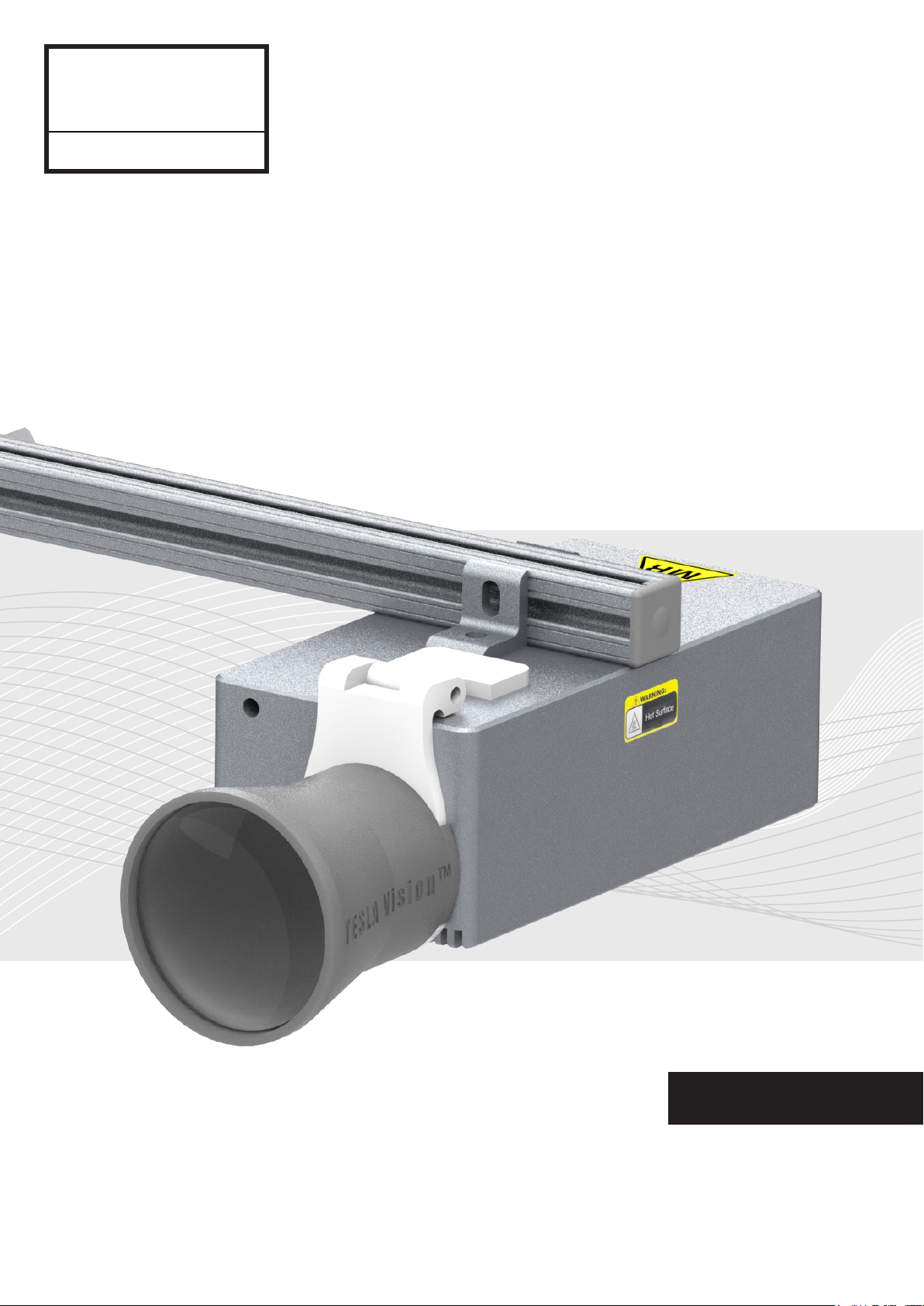
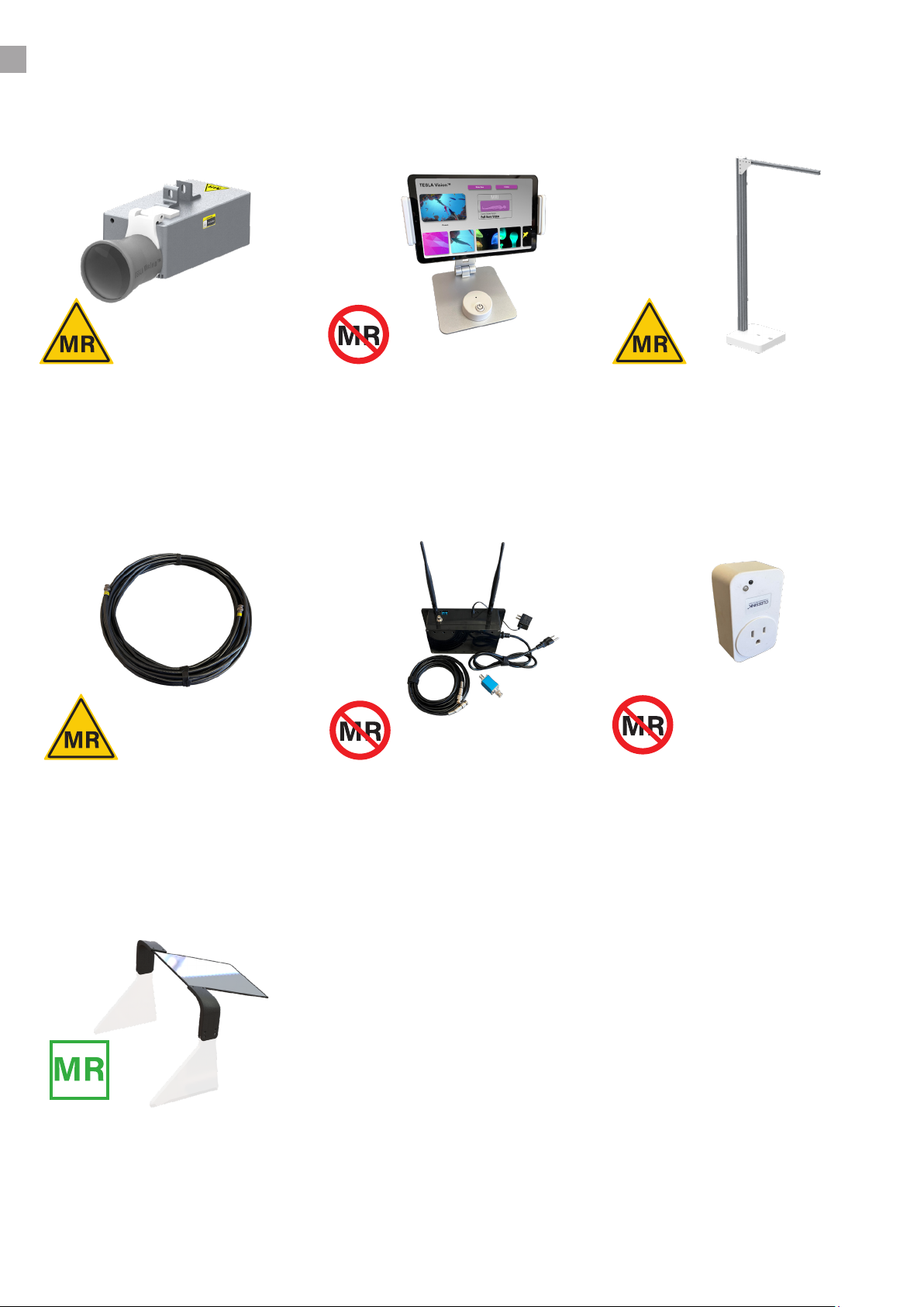
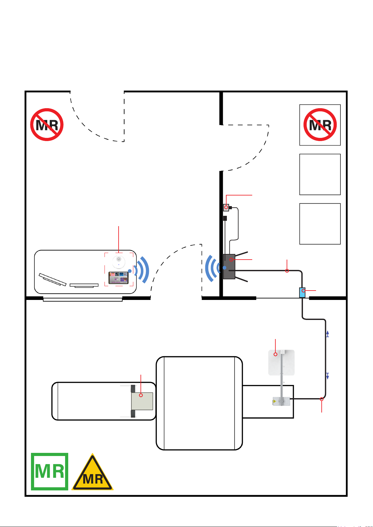
The Tesla Vision is an MR Conditional video solution that allows patients to view passive scenery
and videos while undergoing an MRI scan.
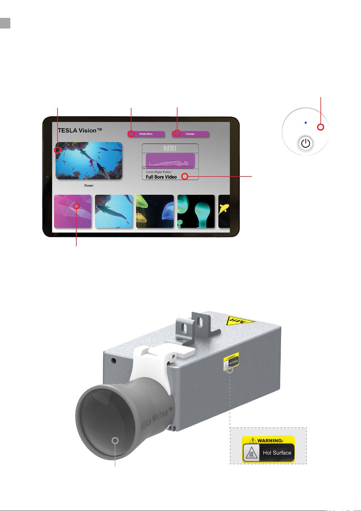
The projector system has two settings for displaying video.
- Setting 1 (Whole Bore) will cover the entire MRI bore surface with passive scenery.
- Setting 2 (Cinema) will focus the video above the patients face when undergoing head or
abdominal scans.
The visually soothing virtual environment displayed directly on the bore of the magnet can help
patients relax during their scan.
The Tesla Vision is intended to provide a visual distraction in MRI environments up to,
and including, 3.0 Tesla. The product is not intended for medical diagnosis or treatment.
Technologist control units are intended to be used outside of the MRI scan room.
Caution: Portable RF communications equipment (including peripherals such as antenna cables
and external antennas) should be used no closer than 30 cm (12 inches) to any part of the Tesla
Vision, including its cables. Otherwise, degradation of the performance of the system could
result.
Caution: Use of accessories, cables, and other equipment not specied or provided by
UX Platforms, Inc. could result in increased electromagnetic emissions or decreased
electromagnetic immunity of the equipment and result in improper operation.
Caution: Use of its equipment adjacent to or stacked with other equipment should be avoided
because it could result in improper operation. If such use in necessary, this equipment and the
other equipment should be observed to verify that they are operating normally.
2
CLEANING THE DEVICE
- TESLA Vision Projector: Use a clean microber cloth and soapy water to clean the projector
lens.
- Mirror Arch Display: Use a clean microber cloth saturated with soapy water to clean the rst
surface mirror. Caution: Be careful not apply to much pressure to the surface of the mirror it
may lead to abrasions and degrade image quality.
- Tablet Surface: Use a clean microber cloth and soapy water to clean the tablet surface.
All other equipment can be cleaned with Sani Wipes or a cloth lightly saturated with rubbing
alcohol.
DO NOT use any solvent containing bleach.

WARNINGS AND CAUTIONS
WARNING
Please read this manual and follow its instructions carefully. The words, warning, caution and
note carry special meaning and should be carefully reviewed:
Warning: Indicates risks to the safety of the patient or user. Failure to follow warnings may
result in injury to the patient or user.
Caution: Indicates risk to equipment. Failure to follow cautions may result in product damage.
To avoid potential serious injury to the user and the patient and/or damage to this device,
please note the following warnings:
- Check for any obvious damage prior to using equipment. If damage is detected, refer to the
standard warranty.
- DO NOT plug any additional devices into the power block dedicated for the Tesla Vision Wi-Fi
power box located in the computer room.
- The voltage within the projector device may have sucient magnitude to cause electric shock,
therefore; it is dangerous to modify or make any kind of contact with any electrical parts inside
the device.
- Make sure the rolling mount assembly is fully locked into the permanent oor bracket. Failure
to do so may result in the projector system becoming o balance and falling to the ground.
- No modication of this equipment is allowed.
- Warning: The projector unit’s surfaces act as a heat sink for eectively cooling the device and
may be hot.
The projector unit has a minimal amount of ferrous material and is
considered MR Conditional. DO NOT introduce the projector unit to the
opening of the MRI bore. Serious injury or death may occur to patients
or the individual handling the equipment, due to the high strength of
the MRI magnetic eld.
Please be aware that some components are MRI Unsafe. The OEM
packaging will be labeled to indicating MRI safety information.
It is critically important that only MR Safe and MR Conditional
components be taken into and installed in the MRI suite.
3

4
REPORTING INCIDENTS
Contact the manufacturer immediately to report an incident and/or injury to a patient, operator
or maintenance employee that occurred while using the Tesla Vision system and do not operate
the equipment until an investigation is conducted.
EMERGENCY PROCEDURE
In the unlikely event that either the Tesla Vision system or any component of the system creates
smoke, sparks, or if the patient requires emergency assistance:
- Stop the scan if one is in progress.
- Remove patient from the MRI Room.
- Power down the projector system, if possible, by locating the power block located in the
computer room and disconnecting it from the wall outlet.
MRI SAFETY INFORMATION
Shown below are the MRI safety indicators for all parts included in the Tesla vision system.
These ratings will be displayed next to each component listed in this user manual for your
reference.
MR Safe: The device is completely nonmagnetic, non-electrically conductive
and non-radio frequency reactive, therefore eliminating all primary and
potential risks during MRI scanning.
MR Conditional: The device may contain magnetic, electrically conductive
or radio frequency-reactive components that are safe for operation in
proximity to the MRI, provided the conditions for safe operation are dened
and observed (both for the MRI scanner and the device itself).
MR Unsafe: Objects that are signicantly ferromagnetic and pose a clear
and direct threat to persons and equipment within the magnet room.

ITEM CHECK LIST
Below is a list of the major components the system is comprised of. Their description and MRI
safety information are also provided.
●All the components listed above will be referenced
throughout the used guide. In depth descriptions and
functionality will be conveyed through technical illustrations
and text body.
●Please make sure to follow all instructions on intended
use and adhere to all warnings and cautionary instructions
when operating the Tesla Vision system.
Tesla Projector
RF Shielded BNC Cable
Control Units
Wi-Fi / Power Box
Rolling Mount Assembly
Power Block
This component displays video
onto the surface of the MRI
Bore. Always Keep 2’ from the
MRI bore opening.
Placed in MRI room
This component sends power
& Wi-Fi signal to the projector.
Placed in MRI room.
These components allow
technologists to choose
videos and power on/o the
projector wirelessly.
Placed on tech desk
Receives signal from the tablet
and projector. The projector is
powered by this box.
Placed in computer room
Positions the projector safely
behind the MRI bore. Utilizes
a locking bracket permanently
mounted to the oor.
Placed in MRI room
This component provides
power to the projector ONLY.
It is operated by the wireless
power button on the tech
desk.
Placed in computer room
5
Mirror Arch Display
Placed on patient bed.
Displays cinema videos above
the patient onto bore surface.
Placed in MRI room.

CONTENTS
1.
2.
3.
Device description .................................................................................................... 2
Indications for use .................................................................................................... 2
Cleaning the device ................................................................................................... 2
Warnings & Cautions ................................................................................................ 3
MRI Safety information ............................................................................................ 4
Troubleshooting ...................................................................................................... 16
Specications ........................................................................................................... 17
Contact technical support ...........................................................................................
Item check list ............................................................................................................ 5
Contents ..................................................................................................................... 6
Quick start guide & system operation..................................................................... 7
Component diagram ................................................................................................. 8
Instructions & storage ............................................................................................ 12
Safety & indications for use
Troubleshooting & specications
Components & user guides
6

QUICK START GUIDE & SYSTEM OPERATION
7
Powering on/o projector
To power on/o the projector press the
circular power button circled in red.
- A blue LED located above the button will
blink once showing the command was sent.
- Look inside the MRI bore to see if the
projector is ON or OFF.
Key Note: Projector must be powered on
for at least 1-2 minutes before using tablet!
1.
Choosing video
There are a few video genres to choose
from. Select the preferred video by
simply pressing its corresponding
image tab, as shown in the user
interface. Reference pages 8 and 14 for
more detail.
Note: If application does not load check
that the tablets Wi-Fi network is set to
your systems “SKU #”. Do not use any
other network.
Open TESLA Vision app
- Press the power button located on the
side of the tablet, if the tablet is o.
- If using the tablet for patient audio, make
sure the volume is at 100%. The volume
button is next to the power button on the
side of the tablet.
- Press the “TESLA Vision App” tab on the
tablet home-screen.
2.
3.

COMPONENT DIAGRAM
8
Below is a diagram of the control unit that allows the technologist to choose video and power
on/o the projector system. The application interface below is currently set to whole bore.
Reference page 14 for the cinema interface.
Warning Hot Surface
Video Selection Interface
Projector Cinema Lens
Power Button ON/OFF
Video Control Unit & Application
Below is a diagram of the projector unit which displays relaxing passive video onto the surface
of the MRI bore. WARNING: It is possible that the surfaces of the aluminum projector
housing may be hot.
Tesla Projector
Patient Video Position
Current Live Feed Video Whole Bore Cinema Video

COMPONENT DIAGRAM
Below is a diagram of the rolling mount assembly which holds the projector into place. It will be
position behind the MRI bore and to the side of the patient table. Before playing video for the
patient make sure it is fully locked into the oor mount bracket. Check that the lock view-port
only shows the green indicator marking.
Rolling Mount Assembly
9
Floor Mount Bracket
Main Height Adjustment Bracket
Rolling Swivel Base
Lock View-port
180° Swivel ball Race
Swivel Ball
Green lock view-port Indicator
Locked Rolling Mount
Pivot Axel

1
2
34
10
COMPONENT DIAGRAM
Below is a diagram of each component located within and outside the MRI room. Use the table
on page 11 for reference.
Component Locations
Penetration Panel
Computer Room
ZONE 3
Control Room
ZONE 3
MRI Room
ZONE 4
Patient Bed
5
6
7
Wi-Fi Signal / Power
WARNING: Only components labeled MR Safe or
MR Conditional are allowed in the MRI Room.
8

COMPONENT DIAGRAM
Component # Location Component Description
1Control Room
ZONE 3
Control Units: The control unit is placed
on the technologists desk.
Consisting parts: Remote power switch,
tablet, tablet mount
2Computer Room
ZONE 3
Power Block: The remote power block
powers on/o the projector remotely,
from the technologists desk power switch.
Consisting parts: Remote power block
3Computer Room
ZONE 3
Wi-Fi / Power Box: Receives Wi-Fi signal
from the tablet and projector. Also powers
the projector.
Caution:
Router power adapter: The router must
always be powered on. Do not power it
from the “Power Block” only from an open
wall outlet.
Projector Power Adapter: This power
adapter must be plugged into the “Power
Block” to turn on/o the projector re-
motely. All cables will be labeled clearly to
indicate this.
4Computer Room
ZONE 3
15’ BNC Extension Cable: This cable con-
nects the “Wi-Fi / Power Box” to the low
pass “RF Filter” located on the penetration
panel.
5Computer Room
ZONE 3
RF Filter: This low pass lter blocks RF
from entering the MRI room through the
projector unit.
Note: It must be attached to a BNC port
located on the penetration panel.
6MRI Room
ZONE 4
RF Shielded BNC Cable: This 45’ cable
provides Wi-Fi signal and power to the
“TESLA Vision Projector”. It attaches to the
opposing BNC port of the RF Filter and to
the projector unit’s BNC port.
7MRI Room
ZONE 4
TESLA Vision System: The rolling mount
base must be locked into the “Floor Mount
Bracket” for image to be properly aligned.
8MRI Room
ZONE 4
Mirror Arch Display: Placed on the patient
table. Reference “page 14 Instructions”
Component Locations
11
Below is the reference table for components listed 1-8 inside and outside the MRI room.

1
2
INSTRUCTIONS
Unlocking the rolling mount
CAUTION: The projector unit must
be powered OFF before moving it
throughout the MRI room. If powered
ON while moving it through the
magnetic eld you will induce currents
and possibly damage the device.
To move the system, simply grab the
Main Adjustment Pillar and fully pull
it back from the Floor Mount Bracket.
After it’s released, you can move the
device freely throughout the MRI room.
CAUTION: The system can become
unstable if it is not locked into the Floor
Mount Bracket.
1.
Moving/Storing the Projector System
Hold pillar here
Floor Mount Bracket
Locking the rolling mount
Take the Rolling Mount Assembly and
align the black arrow to the adjacent
slot guide located on the Floor Mount
Bracket.
1. Press the Rolling Mount Assembly
into the slot on the Floor Mount Bracket.
2. You will hear an audible click once
locked. When you see the green tab
on the Floor Mount Bracket in the
locking view-port on the Rolling Mount
Assembly, the Rolling Mount Assembly
is fully secured.
2.
12

BNC Cable
Wall
Floor
Wall
Unlocked Locked
13
Storage location
When storing the system away from its bracket, ensure
that it is stored in a low trac area, such as close to a wall/
corner, as shown in the diagram to the left.
3.
Cable management
Safety swivel base mechanism
When moving the system to another location, be aware of
the RF Shielded cable locations. Rolling over it or stacking
objects on it may cause damage and render the system
inoperable.
TheRollingMountAssemblyisequipped
with a swivel base. This mechanism
allows the projector to swing away if it
contacts a patient or other object.
If this occurs, simply push the Rolling
Mount Assembly back into place until
you see the green tab in the view-port
or an audible click is heard.
2.
4.
INSTRUCTIONS
Moving/Storing the Projector System

INSTRUCTIONS
Changing Full Bore Video to Cinema Video
Setting 1: Whole bore video
1.
When displaying whole bore
video the “cinema lens” must be
positioned up until its resting on top
of the projector housing.
This will allow the projector to
display a larger image onto the
entire surface of the MRI bore.
The cinema lens utilizes a hinge
attached to the projector housing
for easy operation and alignment.
Setting 2: Cinema video
2.
When displaying cinema video the
“cinema lens” must be positioned
down until its resting at onto the
projector’s front housing surface.
This will allow the projector to
display a smaller HD image onto the
Mirror Arch Display inside the MRI
bore.
This feature allows patients to
view narrative HD videos during
abdominal, neck and head scans.
14

INSTRUCTIONS
Mirror Arch Display
Positioning the Mirror Arch display
1.
Position the patient on the MRI bed
with or without a coil depending on
the scan.
Place the Mirror Arch display over
the patient making sure its centered
on the bed.
The edge of the mirror will be
approximately 2” from the patients
eyes as seen in the gure to the left.
Caution: Only lift the Mirror Arch display with two hands holding both support legs.
Note: The Mirror Arch display only works for head rst scans, not feet rst.
2”
Changing the application to cinema
2.
When using the Mirror Arch display
you will need to switch from “whole
bore” video to “cinema” video.
Press the Cinema tab at the top right
of the tablet screen.
Choose from the video selection
located at the bottom of the screen.
Video Selection
Cinema Video Tab
Intended use for Mirror Arch display
3.
The Mirror Arch display allows
patients to watch narrative video
during abdominal, neck and head
scans. The video image is displayed
on the MRI bore surface.
The Mirror display moves with the
patient bed and always keeps the
video displayed directly above their
eyes.
Video image Projection
15

TROUBLESHOOTING
Please read and carefully follow the troubleshooting suggestions below if you are having issues
with the system.
NOTE: If any component of the system appears to be damaged, please contact UX Platforms.
You may nd the contact information on the last page of this manual.
●System will not power ON/OFF.
- Check if the blue LED is lighting up when pressing the power button. If the LED is not
lighting up, the power button may be damaged. If you do see that the blue LED is lighting up,
but power is not being sent to the device, contact UX Platforms.
●Video will not change.
If the video does not change when selecting from the tablet interface. Proceed by pressing
another video for any of the genres. Check the current live feed video on the tablet interface,
if it is not displaying active video then its most likely signal loss. If this proceeds please
contact support. NOTE: The “video control unit” can only be used after the projector has
been on for 1-2 minutes.
●Rolling mount assembly will not lock into place.
If the Rolling Mount Assembly does not fully lock into the Floor Mount Bracket, back it out,
realign the indicator arrows, and attempt to push it in again; make sure you see the green
tab in the view-port. If the issue persists, please contact UX Platforms.
●The video image is not bright enough on the surface of the MRI bore.
This occurs when the ambient lighting in the MRI room is too bright or the track lighting
located in the MRI bore is on. It is suggested to turn the track lighting o and the room
lighting to a low brightness setting.
●The video image is not aligned with the MRI bore.
Check to make sure the Rolling Mount Assembly is locked into place. Adjust the Rolling
Mount Assembly to align the two green dots in the image with green dots located on the
back of the MRI bore.
16

17
SPECIFICATIONS
The electrical components of this device are not user serviceable. Any con-
tact with the wiring or other electrical components by untrained persons
may result in serious injury or death.
Component Weight
Tesla Projector 3.5 lbs
Rolling Mount Assembly 20 lbs
Wi-Fi / Power Box 7 lbs
Video Control Unit 1.1 lbs
Power Block 2 lbs
BNC Cable 2 lbs
Mirror Arch Display 3.8 lbs
Component Dimensions
Tesla Projector 8” L x 4” W x 3” H
Rolling Mount Assembly 2’ 0.5” L x 1’ W x 5’ 0.9” H
Wi-Fi / Power Box 3”W x 5”H x 8”L
Video Control Unit 12” L x 6” W x 1.25” H
Power Block 6.5” L x 3.5” W x 1.25” H
BNC Cable 45’ L
Mirror Arch Display 17.3” L x 18” W x 13” H
Power Supply / Electrical Specications
Parameter Rating
Input Voltage 90 ~ 264 VAC 50-60Hz
Output Voltage 12V DC 5A
Projector Unit Power Specs / Electrical Specications
Parameter Rating
Input Voltage 9-15V DC 4A max
Portable and mobile RF communications equipment should be used no closer to any part of
the Tesla Vision system, including cables, than the recommended separation distance calculat-
ed from the equation applicable to the frequency of the transmitter.
Recommended separation distance
d=1.2√P - 80MHz to 800 MHz
d=2.3√P - 800MHz to 2.7 GHz
Where P is the maximum output power rating of the transmitter in watts (W) according to the
transmitter manufacturer and d is the recommended separation distance in meters (m).
Field strengths from xed RF transmitters, as determined by an electromagnetic site survey, a)
should be less than the compliance level in each frequency range. b)
Interference may occur in the vicinity of equipment marked with the following symbol:

Note: At 80 MHz and 800 MHz, the higher frequency range applies.
Note: These guidelines may not apply in all situations. Electromagnetic propagation is aected
by absorption and reection from structures, objects and people.
a) Field strengths from xed transmitters, such as base stations for radio (cellular/cordless)
telephones and land mobile radios, amateur radio, AM and FM radio broadcast and TV broad-
cast cannot be predicted theoretically with accuracy. To assess the electromagnetic environ-
ment due to xed RF transmitters, an electromagnetic site survey should be considered. If the
measured eld strength in the location in which the Tesla Vision system is used exceeds the
applicable RF compliance level above, the system should be observed to verify normal oper-
ation. If abnormal performance is observed, additional measures may be necessary, such as
re-orienting or relocating the Tesla Vision system.
b) Over the frequency range 150 kHz to 80 MHz, eld strengths should be less than 3 V/m.
Recommended separation distances between portable and mobile RF communications
equipment and the Tesla Vision system
The Tesla Vision system is intended for use in an electromagnetic environment in which radi-
ated RF disturbances are controlled. The customer or the user of the Tesla Vision system can
help prevent electromagnetic interference by maintaining a minimum distance between por-
table and mobile RF communications equipment (transmitters) and the Tesla Vision system as
recommended below, according to the maximum output power of the communications equip-
ment.
Rated maximum output
power of transmitter
Separation distance according to frequency of transmitter
in meters (m)
150 kHz to 80 MHz
d=1.2√P
80 MHz to 800 MHz
d=1.2√P
800 MHz to 2.7 GHz
d=2.3√P
0.01 0.12 0.12 0.23
0.1 0.38 0.38 0.73
1 1.2 1.2 2.3
10 3.8 3.8 7.3
100 12 12 23
For transmitters rated at a maximum output power not listed above, the recommended sep-
aration distance (d) in meters (m) can be estimated using the equation applicable to the fre-
quency of the transmitter, where P is the maximum output power rating of the transmitter in
watts (W) according to the transmitter manufacturer.
Note: At 80 MHz and 800 MHz, the separation distance for the higher frequency range applies.
Note: These guidelines may not apply in all situations. Electromagnetic propagation is aected
by absorption and reection from structures, objects and people.
Approved Standards & Testing Method
- FCC 47 Part 15, Subpart B: §15.109
- ICES-003: §3.2.2
- Test Method: ANSI C63.4-2014
SPECIFICATIONS
18

Ux
Platforms
UX Platforms, Inc.
Technical support
Tel.: +(858) 519-7304
Email: [email protected]
Web: www.UXPlatforms.com
13330 Tiverton Road, San Diego, CA, 92130
●www.UXPlatforms.com
© UX Platforms, Inc. 2020
This manual suits for next models
1
Table of contents