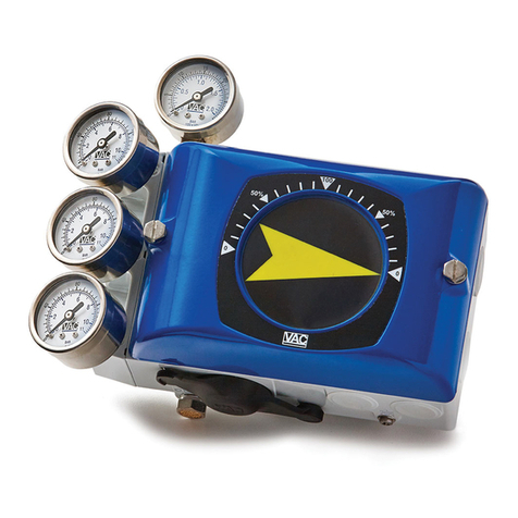
VAC V100 User manual

Trouble Shooting Guide for V100 Positioner
1) 1.V100 not responding to input signal
a) The tubing to the actuator may be
incorrect
i) Plant Air Supply should be ported to
the Sport on the side of the
positioner. Supply must be
greater than 30 PSI.
ii) The pneumatic control signal
(3 to 15 psi) should be ported to
the Ip port on the side of the
positioner.
If the positioner is a V100E, using
an I/P on the positioner, the Ip
port should be plugged tightly!! Double check once plug is in place to make sure
there is no air leakage from Ip plug.
iii) The driving port of this positioner is the C+ port. In other words, on an
increasing control signal the supply is directed through the positioner to the
C+ port. This is very important – not only for single acting
or spring assist valve packages, but also to insure proper
air to open (or close) operation (rotation).
b) I/P wiring
i) Make sure the unit is properly wired.
(1) The positive terminal (+) MUST have a positive
voltage to it.
(2) The negative terminal (-) MUST have a negative voltage to it.
c) I/P operation
i) If the I/P has been in use the potential for contaminated air
supply exist – check the I/P by either of the following steps.
(1) Install a gauge on the I/P gauge port (1/8 inch NPT) to make
sure that the I/P is generating a 3 to 15 psi pneumatic output in correlation to
the 4 to 20 mA input signal.
(2) Using an ohm meter check to make sure that there is resistance still in the
loop. A good unit will put out 240 Ω or more.

d) Cam
i) If cam nut and locking screw are not correctly inserted the positioner will not work
correctly, generally resulting in the cam slipping and a small input change will
equal a full stroking of the actuator. Make sure that the locking screw is all the
way out before you tighten the cam nut; then secure the locking screw
(the cam nut is the first lock – the screw is the second lock). The cam pictured
below is INCORRECT, and will result in cam slipping and full stroking of the
actuator on small input changes.
ii) Make sure that the Positioner action (direct acting or reverse
acting) corresponds with the cam. A “D” or an “R” can be
found on the cam to indicate direction of cam rotation.
(1) An easy way to check this is to remove the cover of the
positioner and watch the rotation to ensure that cam
placement is correct.
e) Spool Valve
i) Dirty air can cause particulates to cause “sticking” and prevent the positioner
from working correctly. (see below hunting)
(1) Remove the spool valve and blow out with air. If air is not available wipe down with cloth.
Once cleaned the spool piece should slide very easily in its housing. Place spool valve back into
positioner making sure that the slotted top of the spool piece is connected
correctly on the balance arm.
f) Gauge Plugs
i) All gauge plugs or gauges must be secure (no air leaks!!). If the
plugs or gauges are not properly tightened air can leak causing the
positioner not to respond to input signal. Note: gauges are very
useful when trouble shooting a positioner. This helps “inspect” the
air flow through the positioner as well as the I/P output. Three 0-160
psi gauges are used for the supply (S port) and two output ports
(C+ and C-). A 0-30 psi gauge is used for the I/P output.
g) Mounting
i) Rotary

(1) The positioner will not work correctly if the positioner is not engaged properly in the actuator.
Check the positioner to actuator coupling to see if the positioner
and actuator are mated correctly.
ii) Linear
(1) Slop – can result when the actuator to positioner components
are loose or improperly connected. A linear arm is what converts
the linear motion to a rotary motion for the positioner. If there is
slop or play in the assembly, it can cause the positioner not to perform correctly. A rule of thumb
when mounting on linear actuators is when at 50% of input signal the linear arm should be at
mid stroke, thus making a 90 angle with the linear arm and the valve stem.
2) Hunting or Oscillation
a) Spool Valve
(1) Remove the spool valve and blow out with air. If air is not available wipe
down with cloth. Something every soft, like a pipe cleaner should be used
to clean the inside of the spool block itself. Once cleaned the spool piece
should slide very easily within the housing. Place spool valve back into
positioner making sure that the top of the spool piece is connected
correctly on the balance arm.
(a) DO NOT USE WD40 or OIL BASED LUBRICANTS TO CLEAN
SPOOL PIECE.
(2) Due to our superior air delivery sometimes on small actuators this can cause
hunting to occur. This can also occur when dealing with damper drives as well,
do to the weight and stroke of the damper.
(a) If there are doubts on which spool valve to order call our service
center at 205.678.0507
(b) Replace standard spool valve with the Low Gain spool valve. VAC
will do an exchange at no cost.

Reversing a positioners action
A common question that Valve Accessories & Controls often gets from the field is that a customer
has a valve package with our positioner however they wish to reverse the input signal and action
of the valve. For example a customer has a valve that is closed at 4mA and open at 20mA. The
below diagrams are 4mA closed and 20mA open. The diagram on the left is a double acting
actuator and the one on the right is single acting.
The customer would now like the opposite from their valve. They would like to have open at
4mA and closed at 20mA. The diagrams below are 4mA open and 20mA closed. The double
acting is on the left and single acting is on the right.
Here is a step by step procedure in getting from 4mA closed and 20mA open to 4mA open and
20mA closed.
For the positioner adjustment, we have to make two key changes:
1-change the actuator/positioner porting
2-change the cam configuration

1. The tubing must be reversed. C+ tube must now go to C- and C- must go to C+.
So for double acting actuators you do exactly that, just reverse the tubing, for single acting,
C+ would now be plugged and C- would now be piped to the actuator.
2. Remove the front cover and the indicator in order to expose the cam nut and cam-notice
the cam position.
3. Loosen the cam nut and take the cam out and flip it over-literally 180 degrees.
Place the cam back in the positioner making sure that it is on the opposite lobe side.
(example: on a C1 cam it would go from the C1 A 90D side to the C1 B 90R side)
DO NOT TIGHTEN THE CAM NUT.
4. a. is for double acting applications, b. is for single acting applications
a. For double acting applications apply supply air to the positioner. This should move the valve
open, the desired 4mA position. Now simply tighten cam nut. Now the positioner will be
working 4mA Open to 20mA close.
b. Since the positioner was set up originally 4mA closed we must now apply air to the
actuator to get the valve
to move to open. This is
done by pushing up on the
balance arm. The
balance arm is labeled #2
in this picture. As you can
see the balance arm is
connected to the spool
valve (#6) through
connection #7. By pushing
up on the balance arm we
are exhausting air out of the
C- port. Once the valve is
open continue to hold the
balance arm up and tighten
the cam nut. Once the cam
nut is tightened release the balance arm, the positioner is now set to operate from
4mA open to 20mA closed.
The positioner should now be operating as 4mA is open and 20mA is closed.
Note: This will not change the “fail safe” action on an actuator with springs (usually
single acting application). To change the fail safe action you should contact the actuator
manufacturer.
Table of contents
Other VAC Controllers manuals
Popular Controllers manuals by other brands

Mitsubishi
Mitsubishi MELSEC-L Series user manual

Deif
Deif GPC-3 Hydro installation instructions

Induction Solutions
Induction Solutions Boogie Box NPC-1006 user manual

Taconova
Taconova FWCK Installation and operating instructions for manual and remote control options

Axis
Axis A1001 installation guide

NOCH
NOCH Servo with Control manual