page 3 of 17
Documents are only to be used and distributed completely and unchanged. It is strictly the users´ responsibility to check carefully
the validity of this document with respect to his product. manual-no.: 999001 / 04/04/2012
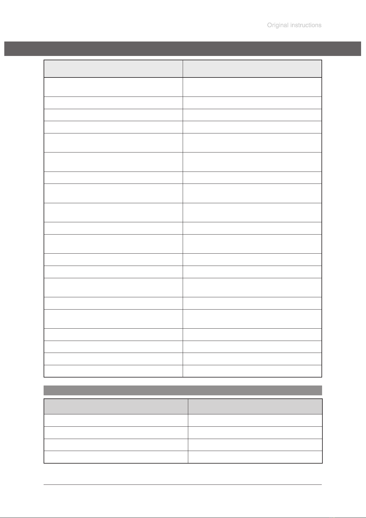
Contents
Safety information! .....................................................................................................4
General information............................................................................................................................4
Intended use.......................................................................................................................................4
Connecting the device .......................................................................................................................4
Operating conditions .........................................................................................................................5
Safety during operation .....................................................................................................................5
Maintenance and repair .....................................................................................................................5
Technical data .............................................................................................................7
Wetted parts ......................................................................................................................................7
Use and operation ......................................................................................................8
Changing the pressure unit ...............................................................................................................8
Pressure measurement .....................................................................................................................9
Clock symbol .....................................................................................................................................9
Adjusting the operating time and the measuring cycle ......................................................................9
Display of the battery‘s discharge status.........................................................................................10
Troubleshooting .......................................................................................................10
Readjustment of the vacuum gauge DVR 2 ...........................................................11
Adjustment at atmospheric pressure ............................................................................................... 11
Adjustment under vacuum............................................................................................................... 11
Adjustment to a reference pressure ................................................................................................12
Calibration in the factory .........................................................................................12
Replacing the battery ...............................................................................................13
Notes on return to the factory .................................................................................14
Health and safety clearance form ...........................................................................15
EC Declaration of Conformity .................................................................................16
➨DANGER indicates a hazardous situation which, if not avoided, will re-
sult in death or serious injury.
☞WARNING indicates a hazardous situation which, if not avoided, could
result in death or serious injury.
• CAUTION indicates a hazardous situation which, if not avoided, could
result in minor or moderate injury.
NOTICE is used to address practices not related to personal injury.
Note: The device contains a battery!
Remove battery before disposal (see section ”Replacing the bat-
tery”) and dispose of battery and device separately and according
to regulations.
NOTICE