PresenterPOD System
PresenterPOD System ●Document Number 342-0212 Rev. B Page 9 of 12
General Specifications
PresenterPOD System
Part Numbers 999-1111-000 North America
999-1111-001 International
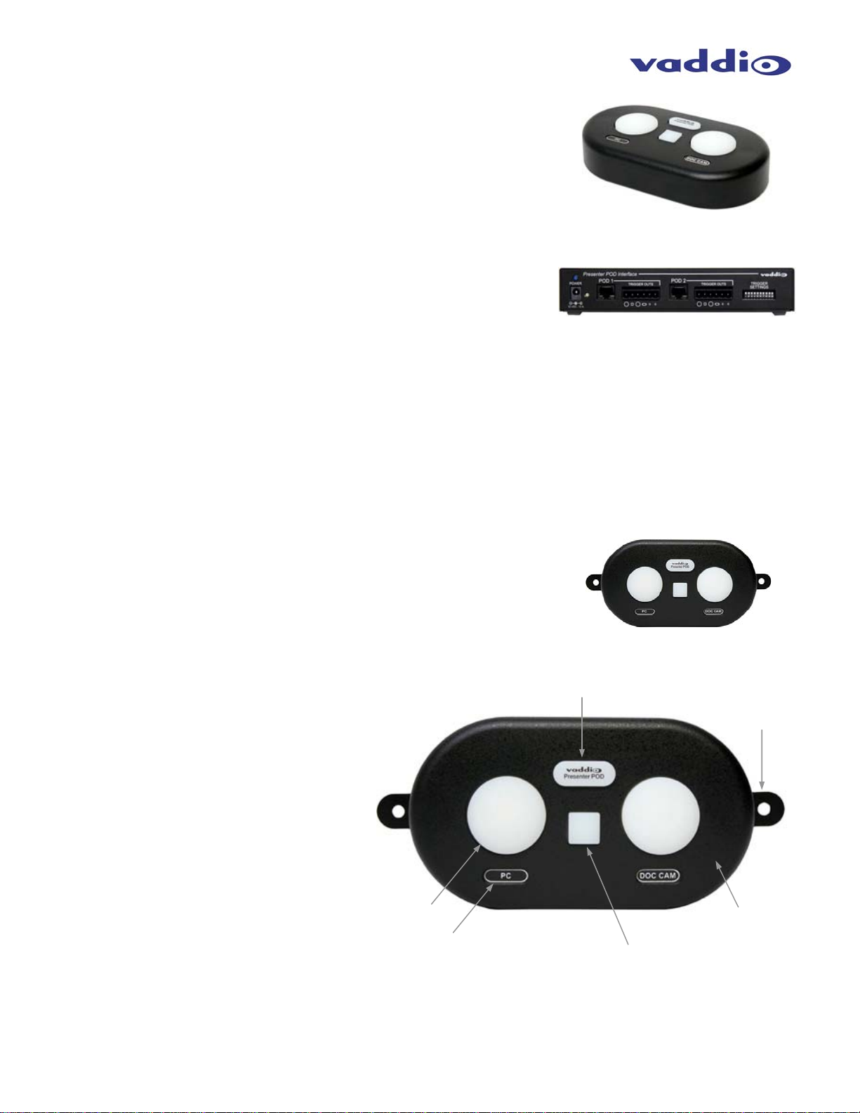
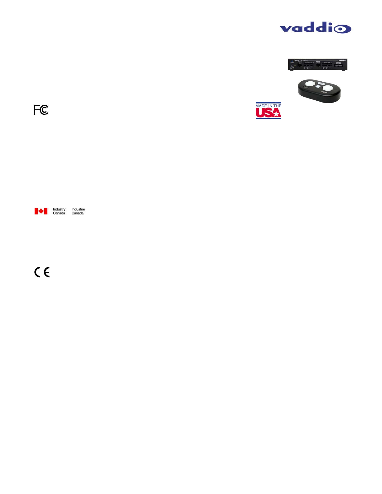
PresenterPOD
Attributes:
•Blue back-lit logo button that turns red when triggered
•Three (3) manual buttons with blue LED backlights
•Two (2) RJ-45 jacks (back and bottom) to connect to the PresenterPOD Interface with one (1) Cat-5e
Cable
•NOTE: use only one RJ-45 at a time on the PresenterPOD
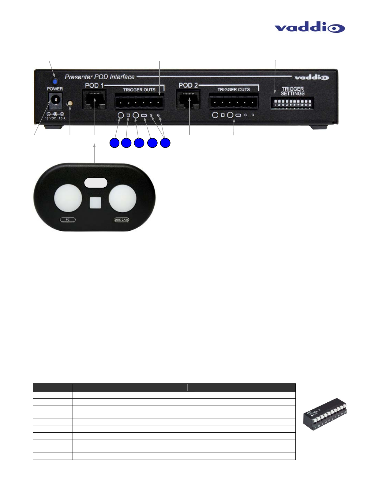
PresenterPOD
Interface:
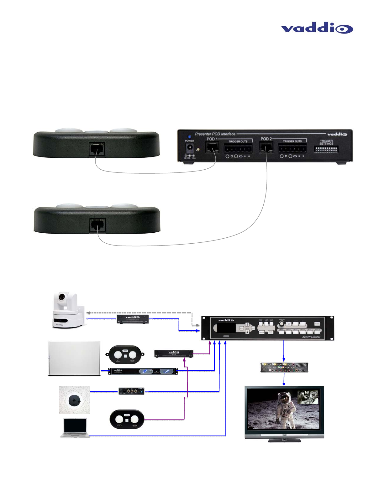
•Each Interface can support two (2) PresenterPODs
•Four (4) trigger outputs per POD
•Phoenix type connectors for Interface trigger outs
•10 Pos. dip switch assigns triggers (latching or momentary)
Connectivity Power and Data between Interface and POD on Cat-5e
Labeling One (1) sheet of 30 adhesive labels provided (both pre-labeled and blanks)
Power Supply PowerRite 12 VDC, 1.0 Amp
Dimensions •PresenterPod Interface: 1.47” (37.34mm) H x 8” (203.2mm) W x 6” (152.4) D
•PresenterPOD: 1” (25.4mm) H x 5.72” (145.29mm) W x 3.21” (81.53mm) D
Weights •PresenterPod Interface: 3.2 lbs (1.45149 kg)
•PresenterPOD: 0.65 lbs (0.294835 kg)
Warranty Information: (See Vaddio Warranty, Service and Return Policies posted on vaddio.com for complete details):
Hardware* Warranty: One year limited warranty on all parts. Vaddio warrants this product against defects in materials and workmanship for
a period of one year from the day of purchase from Vaddio. If Vaddio receives notice of such defects during the warranty period, they will, at
their option, repair or replace products that prove to be defective. Please see Vaddio’s Service Terms and Conditions at vaddio.com for
specific details and policies.
Exclusions: The above warranty shall not apply to defects resulting from: improper or inadequate maintenance by the customer, customer
applied software or interfacing, unauthorized modifications or misuse, operation outside the normal environmental specifications for the
product, use of the incorrect power supply, improper extension of the power supply cable or improper site operation and maintenance.
Vaddio Customer Service: Vaddio will test, repair, or replace the product or products without charge if the unit is under warranty and is
found to be defective. If the product is out of warranty, Vaddio will test then repair the product or products. The cost of parts and labor charge
will be estimated by a technician and confirmed by the customer prior to repair. All components must be returned for testing as a complete
unit. Vaddio will not accept responsibility for shipment after it has left the premises.
Vaddio Technical Support: Vaddio technicians will determine and discuss with the customer the criteria for repair costs and/or replacement.
Vaddio
Technical
Support
can
be
contacted
through
one
of
the
following
resources:
e-mail
support
at
[email protected] or online at www.vaddio.com.
Return Material Authorization (RMA) Number : Before returning a product for repair or replacement, request an RMA from Vaddio’s
technical support. Provide a technician with a return phone number, e-mail address, shipping address, and product serial numbers and
describe the reason for repairs or returns as well as the date of purchase and proof of purchase. Include your assigned RMA number in all
correspondence with Vaddio. Write your assigned RMA number on the outside of the box when returning the product. All products returned
for credit are subject to a restocking charge without exception.
Voided Warranty: The warranty does not apply if the original serial number has been removed or if the product has been disassembled or
damaged through misuse, accident, modifications, or unauthorized repair. Cutting the power supply cable on the secondary side (low voltage
side) to extend the power to the device (camera or controller) voids the warranty for that device.
Shipping and Handling: Vaddio will not pay for inbound shipping transportation or insurance charges or accept any responsibility for laws
and ordinances from inbound transit. Vaddio will pay for outbound shipping, transportation, and insurance charges for all items under warranty
but will not assume responsibility for loss and/or damage by the outbound freight carrier.
• If the return shipment appears damaged, retain the original boxes and packing material for inspection by the carrier. Contact your carrier
immediately.
Products Not Under Warranty: Payment arrangements are required before outbound shipment for all out of warranty products.
*Vaddio manufactures its hardware products from parts and components that are new or equivalent to new in accordance with industry standard practices.
Care and Cleaning
•Do not spill liquids in the product
•Keep this device away from food and liquid
•For smears or smudges on the product, wipe with a clean, soft cloth
•Do not use any abrasive chemicals.
Operating and Storage Conditions:
Do not store or operate the device under the following conditions:
•Temperatures above 40°C (104°F) or temperatures below 0°C (32°F)
•High humidity, condensing or wet environments
•In inclement weather or under severe vibration
•In swimming pools, waterfalls, outer space, bear caves or eagle’s nest
•Dry environments with an excess of static discharge