www.vag-group.com
Technische Änderungen sowie die Verwen-
dung gleich- oder höherwertiger Werkstoffe
bleiben vorbehalten. Darstellungen unver-
bindlich. Technische Informationen entneh-
men Sie bitte unserem Datenblatt KAT-A
1613.
Inbetriebnahme
Putting into operation
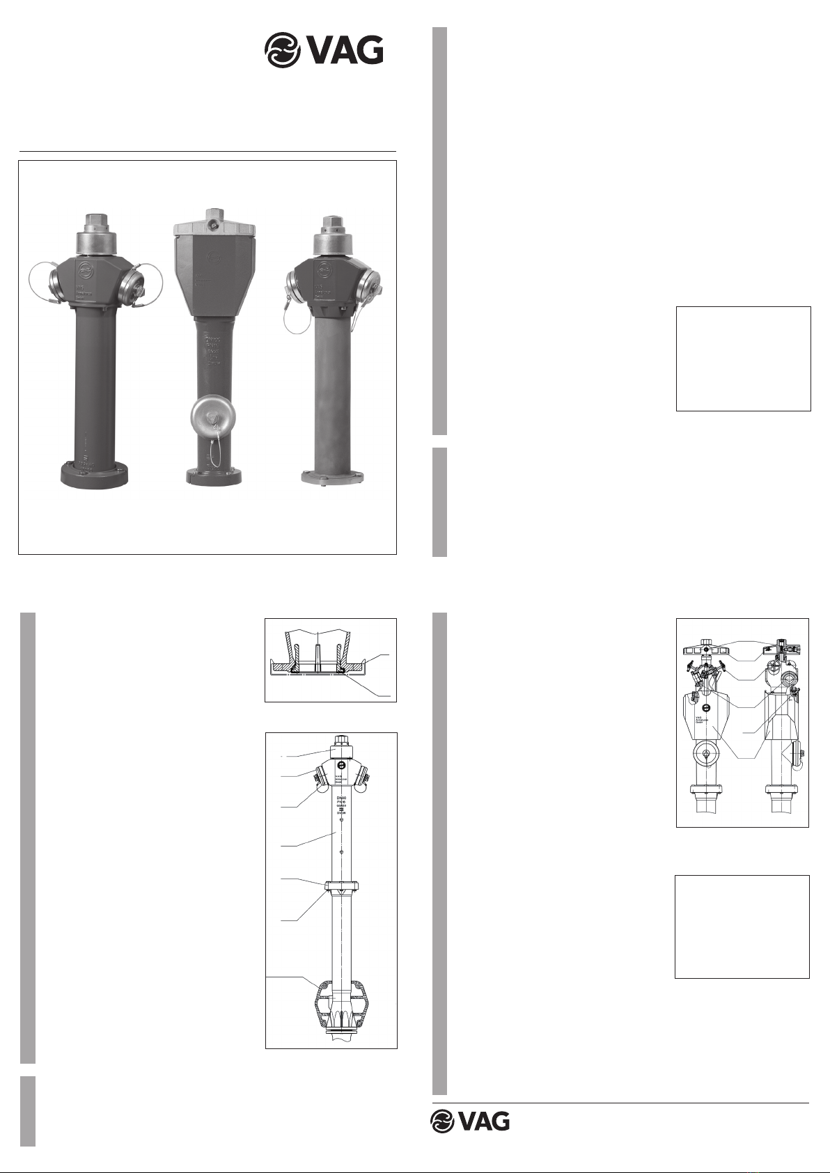
VAG NOVA 284 / NOVA NIRO
Überflurhydrant
VAG NOVA 284 / NOVA NIRO
Standpost Hydrant
2
1Kupplungsstücke und Schläuche ankup-
peln.
• Obere Absperrventile (11) öffnen.
• Mit Betätigungsschlüssel (DIN 3223),
oder direkt von Hand durch gleichmäßi-
ges Linksdrehen des Haubendeckels (9)
die Hauptabsperrung langsam bis zum
deutlich spürbaren Anschlag öffnen.
(11,5 U/Hub).
• Der Sicherungsbolzen (14) wird durch
den entstehenden Druck nach außen
gepreßt und verriegelt den Fallmantel in
der unteren Position.
• Achtung!
Hydranten-Hauptabsperrung muß immer
vollständig bis zum deutlich spürbaren
Anschlag geöffnet werden.
3.2 Schließen Form AFUD
• Hauptabsperrung des Hydranten durch
gleichmäßiges Rechtsdrehen des Hau-
bendeckels (9) bis zum deutlich spürbaren
Widerstand schließen (dabei keinesfalls
unzulässige Betätigungshilfen oder Ver-
längerungen verwenden!).
• Abgangsarmaturen schließen.
• Kupplungsstücke bzw. Schläuche von
den Knaggenteilen abnehmen.
• Entleerung beobachten. Anschließend
Sicherungsbolzen (14) von Hand zurück-
drücken, Fallmantel (13) hochführen und
verriegeln. Nur möglich, wenn
Hauptabsperrung geschlossen ist!
3
Abbildung 1
KAT-B2 1613
Edition 2 / 05-2010
Montage Form AUD und AFUD
• Vor dem Aufsetzen auf die Rohrleitung
Schutzkappe (8) entfernen (Abb. 1).
• Dichtring (7) ist werksseitig unverlierbar
eingepresst und dient als Abdichtung
zum Rohrleitungsflansch (keine Zusatz-
dichtung notwendig).
• Nach dem Aufsetzen des Hydranten auf
den Rohrleitunsflansch Schrauben und
Muttern gleichmäßig über Kreuz anzie-
hen.
• Vor dem Verfüllen des Rohrgrabens zur
sicheren Entleerung des Hydranten ei-
nen passenden Sickerstein (Abb. 2) ein-
bauen.
• Zusätzlich sind die Einbaurichtlinien ge-
mäß DVGW Arbeitsblatt W 331, Ab-
schnitt 5, zu beachten!
• Nach dem Verfüllen ist ein nachträgli-
ches Ausrichten der Oberen Säule (4)
des Hydranten, durch eine spezielle
zweigeteilte Losflanschverbindung (5),
möglich. Dabei werden die Sechs-
kantschrauben (6) an der Bruchmutter-
verbindung gelöst und die obere Säule
(4) in die gewünschte Position gedreht.
Beim Anziehen der Sechskantschrauben
(6) ist darauf zu achten, dass zuerst die
beiden Schrauben an der Verbindungs-
stelle der Flanschhälften angezogen
werden (maximales Anzugsmoment bei
DN 80=25 Nm bei DN 100=38 Nm).
Inbetriebnahmen Form AUD (Abb.2)
2.1 Öffnen Form AUD
• Obere Deckkapseln (2) abschrauben.
Kupplungsstück oder Schlauch mit Ab-
sperrarmatur an die Knaggenteile (3) an-
kuppeln und Absperrarmatur öffnen.
• Betätigungsschlüssel DIN 3223, Ausf. A
oder B, auf Haube (1) stecken und durch
gleichmäßiges Linksdrehen die Hauptab-
sperrung bis zum deutlich spürbaren An-
schlag öffnen.
• DN 80 => 10 Umdrehungen/Hub
• DN 100 => 11,5 Umdrehungen/Hub
• Achtung!
Hydranten-Hauptabsperrung muß immer
vollständig bis zum deutlich spürbaren
Endanschlag geöffnet werden.
• Das Regeln der Entnahmemenge ist nur
durch nachfolgend eingebaute Absperr-
armatur zulässig.
2.2 Schließen Form AUD
• Hauptabsperrung des Hydranten durch
gleichmäßiges Rechtsdrehen der Haube
(1) mit dem Betätigungsschlüssel DIN
3223 bis zum deutlich spürbaren Wider-
stand schließen.
• Kupplungsstücke oder Schläuche von
den Festkupplungen (3) abkuppeln.
• Entleerung beobachten! Deckkapseln (2)
wieder fest aufschrauben.
Inbetriebnahmen AFUD (Abb. 3)
3.1 Öffnen Form AFUD
• Verriegelung des Fallmantels mit Betäti-
gungsschlüssel (gem. DIN 3223) lösen.
Fallmantel (13) ist nun entriegelt und fällt
nach unten.
• An die oberen Festkupplungen (12)
Achtung!
Unbedingt die in der DVGW-
Richtlinie beschrieben Schließ-
reihenfolge beachten:
Zuerst Hydrantenhauptabsper-
rung, dann erst die Abgänge
verschließen.
2
3
Abbildung 3: Hydrant Form AFUD
Achtung!
Unbedingt die in der DVGW-
Richtlinie beschrieben Schließ-
reihenfolge beachten:
Zuerst Hydrantenhauptabsper-
rung, dann erst die Abgänge
verschließen.
8
7
Abbildung 2: Hydrant Form AUD
1
2
3
4
5
6
Sickerstein
10
9
11
12
14
15
Form / Type
AUD
Form / Type
AFUD
Form / Type
AUD


