Vaillant 0-10V VR34 User manual

For the heating engineer
Installation manual
Interface 0-10V VR34
GB

2
Contents
Installation manual Interface 0-10V VR34
Contents
1 Notes on the documentation............3
1.1 Storage of the documents .....................3
1.2 Symbols used ............................................3
2 Safety instructions and
regulations..........................................4
2.1 Safety instructions...................................4
2.2 Regulations................................................4
3 Description of the appliance.............5
3.1 Intended use..............................................5
3.2 CE labelling ................................................5
3.3 Application.................................................5
3.4 Scope of delivery and accessories.......6
3.5 Connections...............................................6
4 Installation..........................................7
5 Electrical installation........................8
6 Recycling and disposal.................... 10

3Installation manual Interface 0-10V VR34
1 Notes on the documentation
The following information is intended to help
you throughout the entire documentation.
Further documents apply in combination with
this installation manual.
We accept no liability for any damage
caused by failure to observe these
instructions.
1.1 Storage of the documents
Please pass on this installation manual to the
owner of the system. It is advised to store all
boiler and accessory manuals together.
1.2 Symbols used
Please observe the safety instructions in this
installation manual for the installation of the
appliance.
dDanger
Immediate risk of serious injury or
death!
aCaution
Potentially dangerous situations for
the product and environment!
hNote
Useful information and instructions!
• Symbol for a necessary task
Notes on the documentation 1

4Installation manual Interface 0-10V VR34
2 Safety instructions and
regulations
This bus coupler must only be installed by a
competent person in accordance with the Gas
Safety (Installation and Use) Regulations
1998. In the UK ‘CORGI’ registered installers
undertake the work in compliance with safe
and satisfactory standard. We accept no
liability for any damage caused by failure to
observe these instructions.
2.1 Safety instructions
dDanger!
Risk of fatal electric shock from
touching live connections. Before
working on the appliance, switch off
the power supply and secure it
against reconnection. Using the
mains switch on the controllers is not
sufficient to isolate all terminals of
the system.
2.2 Regulations
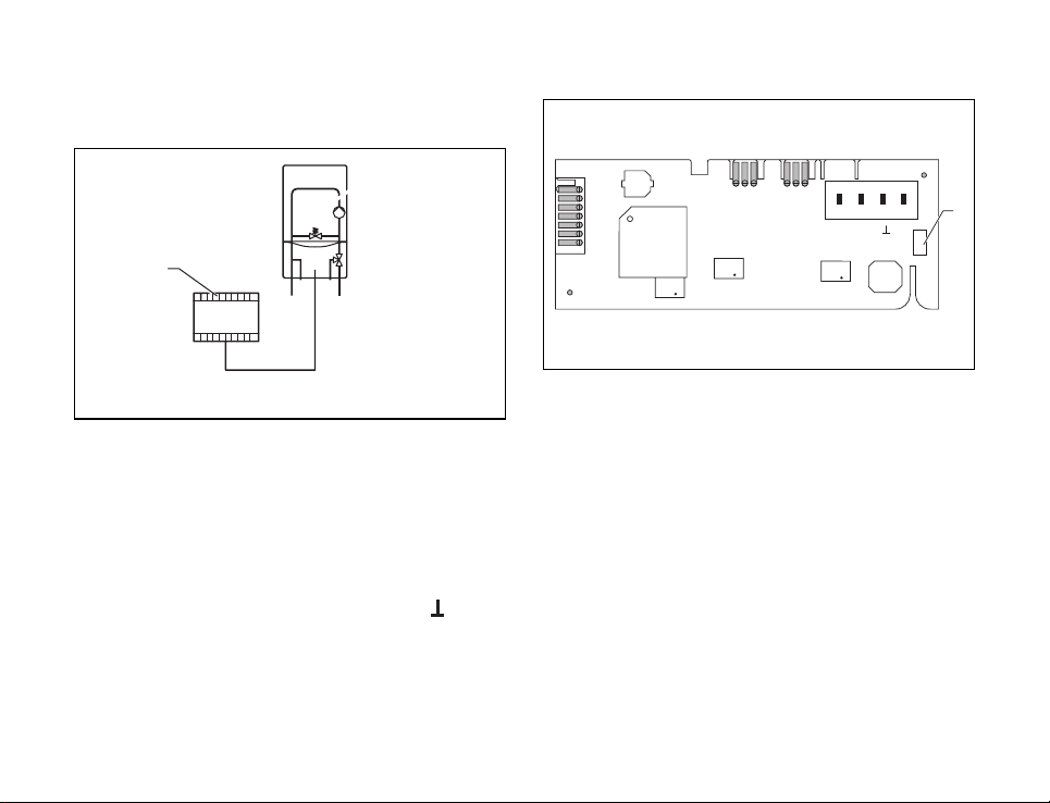
All wiring must be in accordance with Building
Regulations Part P and BS 7671 (IEE Wiring
Regulations), and must be carried out by a
suitably qualified person. Use standard wires
for wiring. Maximum length between VR34
and BEMS 0-10V controller is 6m.
2 Safety instructions and regulations

5Installation manual Interface 0-10V VR34
3 Description of the appliance
3.1 Intended use
The 0-10V VR34 interface allows you to
connect a proprietary Building Energy
Management System (BEMS) with a Vaillant
eBus boiler.
aCaution!
Any use beyond this is considered im-
proper and is prohibited!
3.2 CE labelling
The 0-10V VR34 interface complies with the
relevant directives and standards when
correctly installed according to the
regulations.
3.3 Application
The 0-10V VR34 interface is used to connect
BEMS equipment to a Vaillant boiler with an
eBus interface. It transfers a voltage input on
terminal “I” into a temperature setpoint for
the boiler. Terminal “F” can be used to signal
a boiler fault (24V). This signal will remain
until the fault is corrected and the boiler has
been reset. Use terminal “F” and “24V” to
connect a 24V relay with a maximum current
of 30mA.
Curve 10V-Modul
0
10
20
30
40
50
60
70
80
90
100
024681012
Input voltag
flow temperature setpoint [°C]
up down
hNote:
The earth terminal has ground
potential.
Description of the appliance 3

6Installation manual Interface 0-10V VR34
3.4 Scope of delivery and accessories
• Check the scope of delivery of the bus
coupler.
- 1 VR34 0-10V interface
- 1 connection terminal for eBus line
- 1 cable clamp
3.5 Connections
1
X12
X31
X32
X90
of cu
d
orp
r n
oi
t
E
LD
T
2
24V
I
F
Abb. 3.1 Connections
Key
1 Terminal for connection to boiler
2 BEMS controller terminal
3 Description of the appliance

7Installation manual Interface 0-10V VR34
4 Installation
Mounting the 0-10V interface
• Open the electronics box of the boiler as
described in its installation manual.
• Connect the 0-10V interface and the boiler
with the enclosed cable (2). The boiler
socket and the 0-10V interface are marked
X31
• Install the 0-10V interface (1) in the
electronics box. Push the interface (1) into
the guide (3) in the lower part of the
electronics box, making sure the fastening
clip grips the groove on the partition in the
electronics box.
Abb. 4.1 Connection of bus line to terminal
1
3
2
Abb. 4.2 Installation of interface board
Installation 4

8Installation manual Interface 0-10V VR34
F
I4
2V
4
3
Abb. 4.3 Cable feedthrough
• Secure the 0-10V interface with the
enclosed cable cable clamp (4).
5 Electrical installation
dDanger!
Risk of fatal electric shock from
touching live connections. Before
working on the appliance, switch off
the power supply and secure it
against reconnection. Using the
mains switch on the controllers is not
sufficient to isolate all terminals of
the system.
5 Electrical installation

9Installation manual Interface 0-10V VR34
Connecting the 0-10V interface
1
Abb. 5.1 Connect interface 0-10V
- Connect the external BEMS controller (3) to
the 0-10V VR34 interface. Take care to note
the polarity of the connection.
- The control signal from the BEMS controller
has to be connected to terminal “I”.
Connect the earth lead to terminal ,, “.
X12
X31
X32
X90
ofcud
o
r
p
rno
it
ELD
T
1
24V
I
F
Abb. 5.2 LED
Key
1 Status LED
Electrical installation 5

10 Installation manual Interface 0-10V VR34
Statusdisplay of the LED
The green LED (1) displays the status of the
0-10V interface.
- LED lit without blinking: there is no BEMS
connected or voltage lower 0,5V
- LED blinks fast: no connection to eBus on
boiler
- LED flashes: data transmission between
6 Recycling and disposal
Both the Vaillant 0-10V interface and its
packaging are primarily made of recyclable
raw materials.
Appliance
Do not dispose of your Vaillant 0-10V
interface with household waste. Make sure
that used devices are taken for proper
disposal.
Packaging
Make sure that the packaging is taken for
proper disposal and recycling.
6 Recycling and disposal


0020064149_00 GB 022008
Table of contents
Other Vaillant Recording Equipment manuals