Contents
0020298957_00 Operating and installation instructions 1
Operating and
installation instructions
Contents
1 Safety ............................................ 2
1.1 Action-related warnings ................. 2
1.2 Intended use .................................. 2
1.3 General safety information............. 3
1.4 -- Safety/regulations .................. 3
2 Product description..................... 5
2.1 What do the following
temperatures mean?...................... 5
2.2 What is a zone? ............................. 5
2.3 What is meant by "time period"? .... 5
2.4 Preventing malfunctions ................ 5
2.5 Checking the scope of delivery...... 5
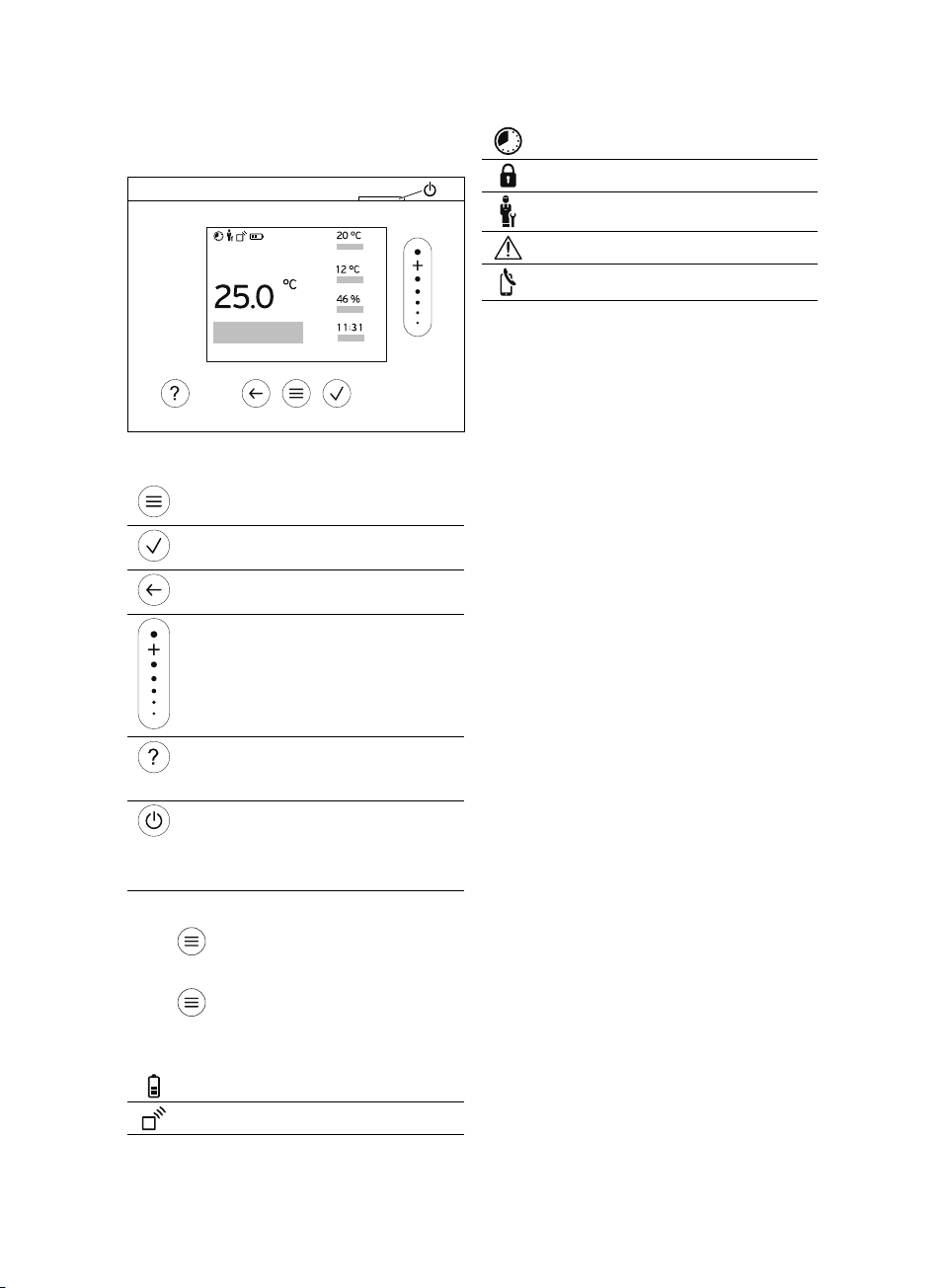
2.6 Display, control elements and
symbols.......................................... 6
2.7 Operating and display functions .... 7
3-- Start-up and set-up.............. 9
3.1 Requirements for start-up.............. 9
3.2 Inserting batteries into the
product........................................... 9
3.3 Installing and setting up the
product........................................... 9
3.4 Configuring the settings on the
system control.............................. 10
3.5 Changing the settings later.......... 10
4 Maintenance ............................... 10
4.1 Changing batteries....................... 10
5 Fault and maintenance
messages ................................... 11
5.1 Fault messages ........................... 11
5.2 Maintenance messages............... 11
6 Information about the
product ....................................... 12
6.1 Observing and storing other
applicable documents.................. 12
6.2 Validity of the instructions ............ 12
6.3 Data plate .................................... 12
6.4 Serial number .............................. 12
6.5 CE marking .................................. 12
6.6 Guarantee and customer
service ......................................... 12
6.7 Recycling and disposal................ 12
6.8 Technical data ............................. 13
Appendix ............................................... 14
A Troubleshooting,
maintenance message .............. 14
A.1 Troubleshooting........................... 14
A.2 Maintenance messages............... 14
B-- Troubleshooting,
maintenance message .............. 14
B.1 Troubleshooting........................... 14
B.2 Maintenance messages............... 15