8Operating and installation instructions 0020253110_03
The data plate contains the following in-
formation:
Information on the
data plate
Meaning
Serial number for identification;
7th to 16th digits
= product article
number
VR 91f Product designation
V Rated voltage
mA Rated current
Read the instructions
LR06 Battery type designa-
tion
T60 Max. permitted envir-
onmental temperat-
ure: 0 to 60 °C
2.2.5 Serial number
You can call up the serial number to the
display under Menu →Information →
Serial number. The 10-digit article num-
ber is located in the second line.
2.2.6 CE marking
The CE marking shows that the products
comply with the basic requirements of the
applicable directives as stated on the de-
claration of conformity.
The manufacturer hereby declares that the
type of radio equipment that is described
in these instructions complies with Direct-
ive 2014/53/EU. The complete text for the
EU Declaration of Conformity is available
at: http://www.vaillant-group.com/doc/doc-
radio-equipment-directive/.
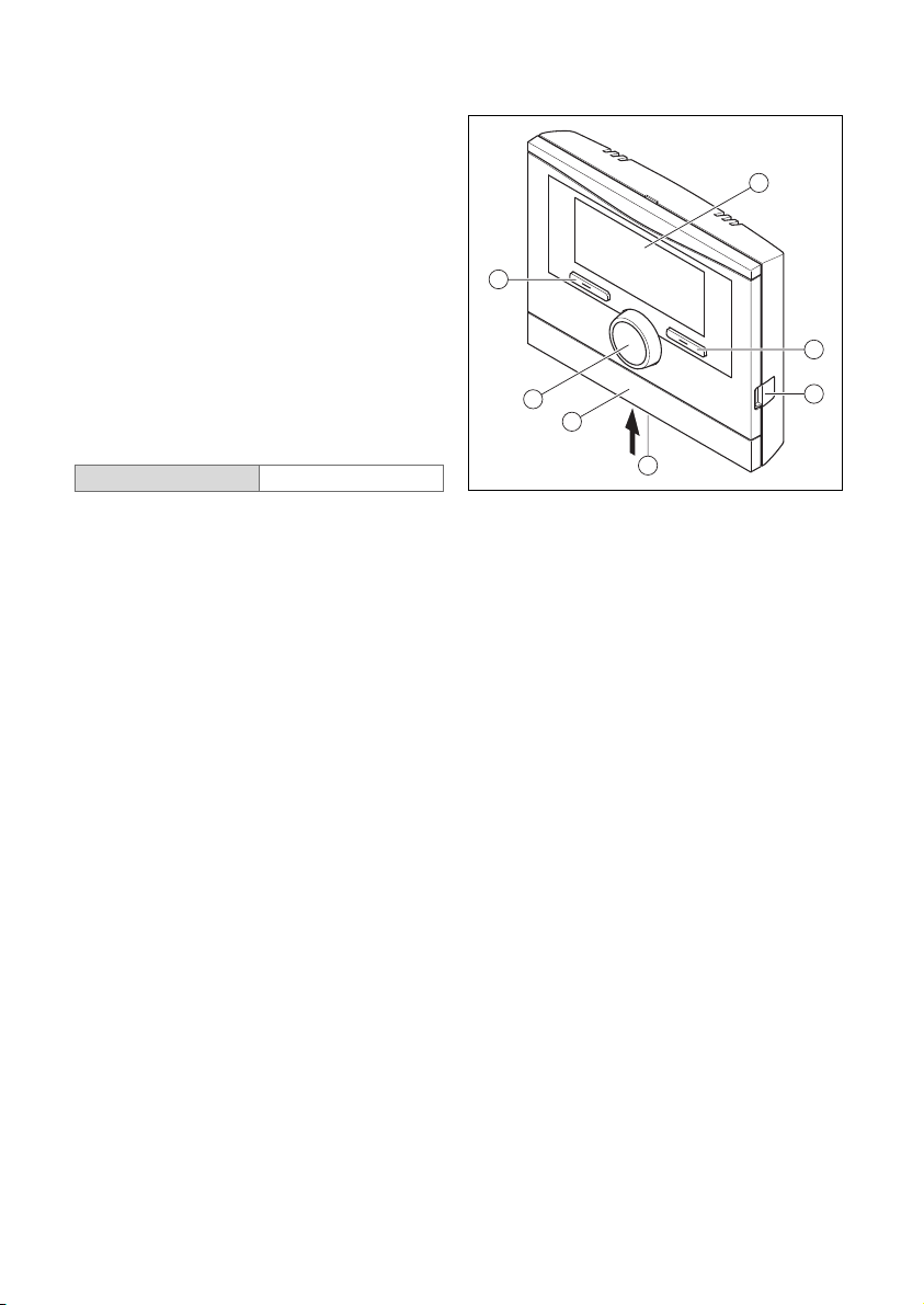
2.3 Operation
You can only operate the remote control
unit in combination with the VRC 700f sys-
tem control. This means that it is also ne-
cessary to read through the operating in-
structions for the VRC 700f system con-
trol.
The operating instructions for the system
control will provide you with
–Information on the operating structure.
–Information on the operating concept
with examples.
–A detailed description of the operating
and display functions that the remote
control unit also has.
Operating modes (→Page 17)
Operating levels (→Page 17)
The path details given at the start of each
function description indicate how you
reach this function in the menu structure.
2.3.1 Reading the reception strength
Menu →Information →System status →
Signal strength
–You can use this function to read how
strong the radio link between the radio
receiver unit and the remote control is.
–4: The radio link is within the acceptable
range. If the reception strength is < 4,
the radio link is not stable.
–10: The radio link is highly stable.
2.3.2 Reading the battery status
Menu →Information →System status →
Battery status
–You can use this function to read the
battery's state of charge.
–OK: The battery has sufficient charge.
–Critical: The battery is almost flat.