VALCOBABY 455919 User manual

1
Quick Sheet Instructions
FUZE CONTROL PAN W/PROXIMITY SENSOR
455919, 455920, 455921,
455922, 455923, 455924
OVERVIEW WARNING!
DISCONNECT POWER BEFORE INSTALLING
OR SERVICING THIS EQUIPMENT!
The control pan is typically used at the END-OF-LINE feeder
tube applicaons, as shown in Figure 1. It may also be used
in MID-LINE installaons.
Figure 1
Sensor Specicaons
Voltage: 20-280VAC/VDC
Frequency: 47-63 Hz
Time delay (adjustable): 0.1-60 sec.
Do not route wires from motor and control switch that are aached to ceiling under sheet
metal plate. They can get tangled and cut during winching.

2
4. Fasten the (2) 451008 Tube Clamps onto the Port Tube,
one on each side of the Control Pan, around the two (2)
ends of each 820158 Non-Swing Brackets as shown in
Figure 4 and 5.
Figure 4
TIGHTEN THE 451008 TUBE CLAMPS OVER THE
820158 NON-SWING BRACKET TABS AND AS
CLOSE TO THE CONTROL PAN AS POSSIBLE.
Figure 5
5. Aach the 750437 Proximity Sensor to the 820177
Mounng Bracket using the 455928 Hose Clamp, leaving
1.06 (1-1/6” or 2.69 cm) of the wiring end of the sensor
beyond the bracket as shown in Figure 6.
6. Mark the locaon of the inseron point with a magic
marker. Draw a line .50” (1/2” or 12.7mm) from the
other end of the sensor as shown in Figure 6. This will
be used to posion the sensor into the Feeder Tower.
Figure 6
Installaon Instrucons
1. Remove the FE1550 Feeder Tower Cap from assembly by
sliding it o (if pre-assembled) the Control Pan.
2. Li the Control Pan onto the boom of the Port Tube
centered under the Feed Drop Hole. Orient the Proxim-
ity Switch mounng hole of Feeder Tower as shown in
Figure 2, on the opposite side of drive unit.
3. Slide the FE1550 Feeder Tower Cap onto the Feeder
Tower tabs as shown in Figure 3.
Figure 3
Figure 2

3
Proximity Sensor Adjustment
LED Indicaton Sensor Status Feed Line
RED ON Sensor output is ON closed No feed detected, motor ON
RED OFF Sensor output is OFF open Feed detected, motor OFF
RED slow ashing Sensor delay is acve sll open No feed detected, motor sll OFF
8. Use the small screwdriver, included with shipping, to adjust the SENSITIVITY on the sensor CCW unl it can no lon-
ger be rotated. This will set the proximity to the least sensive seng. Adjust the DELAY screw CW. This will set the
sensor to the longest me delay as shown in Figure 8.
9. When the feed in running line lls Control Pan Tower and begins to bypass the Control Tower, quickly adjust SENSI-
TIVITY screw CW unl feed line motor stops, then turn a fracon more.
10 . Vibrate the Control Pan to sele feed, adjust DELAY screw CCW to desired me of delay.
11 . Repeat and adjust as necessary unl desired seng is achieved. NOTE: O me delay is adjustable from 1-60 sec-
onds. Val-Co® recommends 60 second delay to prevent excessive feed line cycling.
Turn (once) 240 degrees trimmers-e.g. sensivity and delay - see product label for details.
Figure 8
7. Insert the Proximity Sensor into the Feed Tower .50”
(1/2” or 12.7mm) up to the marked witness line drawn
in Figure 6 on previous page and as shown in Figure 7 to
the right. Aach the Sensor Bracket to the Feed Supply
Tube with the 451008 Hose Clamp. Then connect the
Sensor Wire to power source as indicated in the wiring
diagrams on the page 4.
Figure 7 .50”
1.06”
TO POWER SOURCE
Depending on feed and condions, feed can
somemes buildup on the proximity sensor and
cause early shuto. To remedy the situaon,
spray with stac guard (available at most stores
in the laundry secon) before you install the
sensor or as necessary. Once dry, reinstall the
sensor into the Fuze Tower. Depending on your
condions, you may want to make this a roune
maintenance check.
451008

4
Wiring Diagrams

5
U:\MANUALS\990000\990139
JDS/LRA REV (1) 6-29-2017
North America:
Phone: 800.99VALCO (800.998.2526)
Fax: 419.678.2200
Email: [email protected]om
Internaonal:
Phone: (+1) 419.678.8731
Fax: (+1) 419.678.2200
Email: intl.sales@val-co.com
©2016 Valco Companies, Inc.
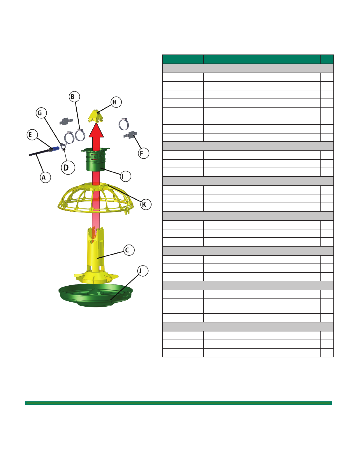
Key Part # Descripon Qty
Interchangeable Parts
A 450965 3/8” CABLE COVER 2
B 451008 1-3/4” SS TUBE CLAMP 3
C 455926 FUZE PROX CONTROL TOWER 1
D455928 7/8” HOSE CLAMP 1
E750437 SENSOR, PROXIMITY, DOL26 1
F820158 FUZE NON-SWING BRACKET 2
G 820177 BRACKET, PROX SENSOR MTG 1
H FE1550 FUZE FEEDER TOWER CAP 1
(parts specic to) 455919
IFE1540 FUZE ADJ COLLAR - STANDARD PAN 1
J FE1610S 14” FUZE SLOTTED STANDARD PAN W/ HINGE & LOCK 1
K FE1620R 14” FUZE PRO GRILL - 14 SPOKE W/ HINGE & LOCK 1
(parts specic to) 455920
IFE1540 FUZE ADJ COLLAR - STANDARD PAN 1
J FE1510S 13” FUZE SLOTTED STANDARD PAN W/ HINGE & LOCK 1
K FE1520R 13” FUZE PRO GRILL - 13 SPOKE W/ HINGE & LOCK 1
(parts specic to) 455921
IFE1540S FUZE ADJ COLLAR - SHALLOW PAN 1
J FE1510LS 13” FUZE SLOTTED SHALLOW PAN W/HINGE & LOCK 1
K FE1520R 13” FUZE PRO GRILL - 13 SPOKE W/ HINGE & LOCK 1
(parts specic to) 455922
IFE1540S FUZE ADJ COLLAR - SHALLOW PAN 1
J FE1610LS 14” FUZE SLOTTED SHALLOW PAN W/ HINGE & LOCK 1
K FE1620R 14” FUZE PRO GRILL - 14 SPOKE W/ HINGE & LOCK 1
(parts specic to) 455923
IFE1540 FUZE ADJ COLLAR - STANDARD PAN 1
J FE1610S 14” FUZE SLOTTED STANDARD PAN W/ HINGE &
LOCK
1
K FE1820R 14” FUZE PRO GRILL - 5 SPOKE W/ HINGE & LOCK 1
(parts specic to) 455924
IFE1540S FUZE ADJ COLLAR - SHALLOW PAN 1
J FE1610LS 14” FUZE SLOTTED SHALLOW PAN W/ HINGE & LOCK 1
K FE1820R 14” FUZE PRO GRILL - 5 SPOKE W/ HINGE & LOCK 1
Standard Pan , Fuze Adj Collar for Standard Pan
and 13 Spoke with Hinge & Lock shown
Control Exploded View and Parts List
This manual suits for next models
5
Table of contents
Popular Accessories manuals by other brands

NeuLog
NeuLog NUL-211 quick start guide

Soehnle
Soehnle COMFORT PRIMO operating instructions

Keith McMillen Instruments
Keith McMillen Instruments SoftStep Reference manual

CAME
CAME MR8107 quick guide

Siemens
Siemens 5WG1 201-2DBx3 Series Technical product information

MAXBOTIX
MAXBOTIX MaxSonar quick start guide