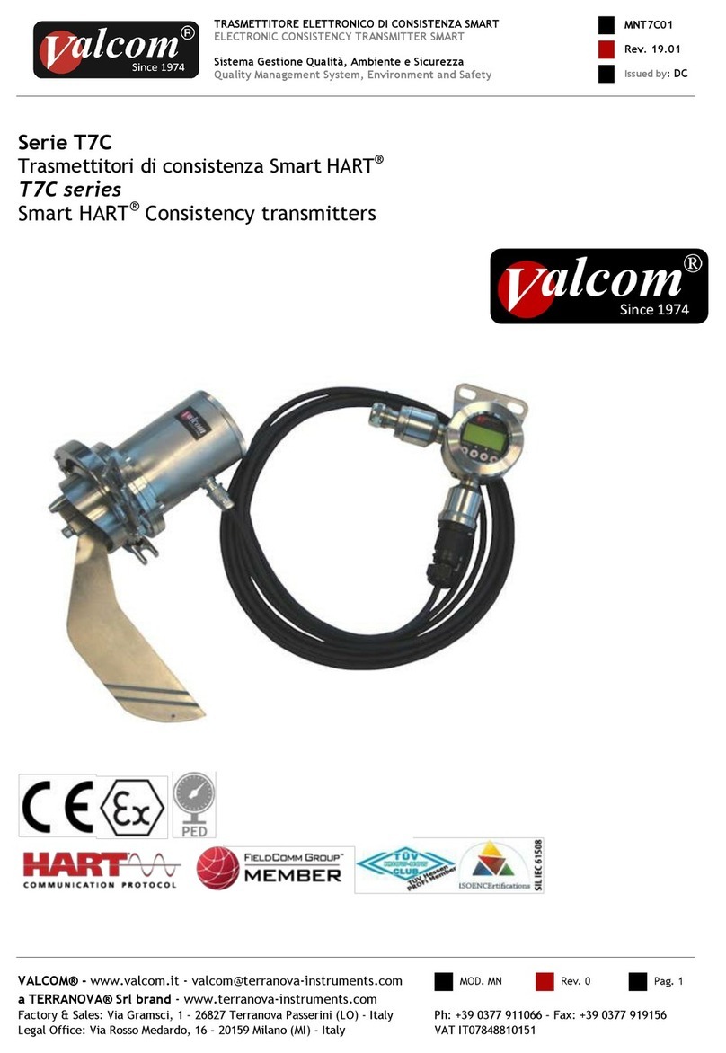
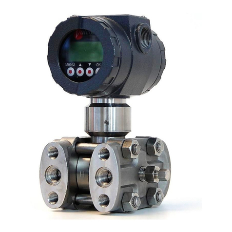
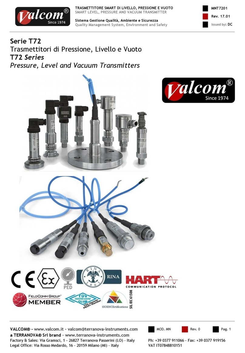
Valcom 27A Series User manual

TRASMETTITORE ELETTRONICO DI LIVELLO, PRESSIONE E VUOTO
ELECTRONIC LEVEL, PRESSURE AND VACUUM TRANSMITTER
Sistema Gestione Qualità, Ambiente e Sicurezza
Quality Management System, Environment and Safety
MN27A01
Rev. 17.01
Issued by:DC
VALCOM® - www.valcom.it - valcom@terranova-instruments.com
MOD. MN
Rev. 0
Pag. 1
a TERRANOVA® Srl brand - www.terranova-instruments.com
Factory & Sales: Via Gramsci, 1 –26827 Terranova Passerini (LO) - Italy
Ph: +39 0377 911066 –Fax: +39 0377 919156
Legal Office: Via Rosso Medardo, 16 –20159 Milano (MI) - Italy
VAT IT07848810151
Serie 27A-27D
Trasmettitori di Pressione, Livello e Vuoto
27A-27D Series
Pressure, Level and Vacuum Transmitters
27A
27D

TRASMETTITORE ELETTRONICO DI LIVELLO, PRESSIONE E VUOTO
ELECTRONIC LEVEL, PRESSURE AND VACUUM TRANSMITTER
Sistema Gestione Qualità, Ambiente e Sicurezza
Quality Management System, Environment and Safety
MN27A01
Rev. 17.01
Issued by:DC
VALCOM® - www.valcom.it - valcom@terranova-instruments.com
MOD. MN
Rev. 0
Pag. 2
a TERRANOVA® Srl brand - www.terranova-instruments.com
Factory & Sales: Via Gramsci, 1 –26827 Terranova Passerini (LO) - Italy
Ph: +39 0377 911066 –Fax: +39 0377 919156
Legal Office: Via Rosso Medardo, 16 –20159 Milano (MI) - Italy
VAT IT07848810151
Introduzione
Questo manuale non contiene tutte le informazioni
relative ad ogni tipo di apparecchiatura, né prende
in considerazione tutti i possibili casi di montaggio,
di funzionamento o di manutenzione.
Per maggiori informazioni o per problemi particolari
non considerati nel manuale Vi preghiamo di
rivolgerVi al nostro ufficio tecnico.
La garanzia è quella prevista nelle ns. condizioni
generali di assistenza. Tale garanzia non viene né
ampliata né limitata da quanto contenuto in questo
manuale.
Attenzione!
Questo strumento deve essere installato ed
utilizzato solo da personale qualificato che abbia
precedentemente verificato la correttezza della
alimentazione in modo che sia in funzionamento
normale, sia in caso di guasto dell'impianto o di sue
parti nessuna tensione pericolosa possa arrivare
all'apparecchiatura. Poiché lo strumento può essere
utilizzato sia con alte pressioni sia con sostanze
aggressive va tenuto presente che un uso non
corretto può portare danni gravi a persone e cose.
Un funzionamento corretto e sicuro presuppone un
adeguato trasporto, immagazzinamento e montaggio
nonché una manutenzione appropriata. E' pertanto
necessario affidare l'apparecchiatura a persone che
abbiano esperienza con il montaggio, la messa in
servizio ed il funzionamento e che siano in possesso
dei titoli per svolgere la loro attività con
riferimento agli "Standard di Sicurezza".
La Società si riserva il diritto
di modificare il contenuto di
questo manuale senza preavviso.
Nota:
Per gli strumenti in versione ATEX le indicazioni
contenute nel presente manuale vanno integrate
con le prescrizioni contenute nelle istruzioni di
sicurezza supplementari.
Introduction
This manual does not contain information
concerning all type of transmitters or all different
installation and/or working and mounting solutions.
For more information or for particular problems
not considered in this manual, please address to our
technical office.
The warranty period is the one contemplated in
our general servicing conditions. This warranty is
neither increased nor restricted by the contents of
this manual.
Attention!
This instrument has to be installed and used only by
qualified persons who have first checked the
correctness of supply voltage so that both in
standard working conditions and in presence of
damages of the plant or of any part of it, no
dangerous voltage can reach the instrument.
As the instrument can be utilized both with high
pressure values and with aggressive media it must
be considered that an incorrect use of it could bring
even serious damages to people and things. A
correct and safe working needs an adequate
transport, stock and mounting other than an
appropriate maintenance service. So it is necessary
for the people handling these apparatus to have
knowledge and experience in mounting, servicing
and working and to have title to do their job with
reference to “Safety Standards“.
The Company could modify this
manual in any moment
without previous advice.
Note:
For ATEX version instruments, the guidelines
included in this manual should be integrated with
the prescriptions included in supplementary safety
instructions.

TRASMETTITORE ELETTRONICO DI LIVELLO, PRESSIONE E VUOTO
ELECTRONIC LEVEL, PRESSURE AND VACUUM TRANSMITTER
Sistema Gestione Qualità, Ambiente e Sicurezza
Quality Management System, Environment and Safety
MN27A01
Rev. 17.01
Issued by:DC
VALCOM® - www.valcom.it - valcom@terranova-instruments.com
MOD. MN
Rev. 0
Pag. 3
a TERRANOVA® Srl brand - www.terranova-instruments.com
Factory & Sales: Via Gramsci, 1 –26827 Terranova Passerini (LO) - Italy
Ph: +39 0377 911066 –Fax: +39 0377 919156
Legal Office: Via Rosso Medardo, 16 –20159 Milano (MI) - Italy
VAT IT07848810151
Sommario / Index
Introduzione ........................................................................................................................................... - 2 -
Introduction............................................................................................................................................ - 2 -
Sommario / Index................................................................................................................................... - 3 -
Descrizione degli strumenti................................................................................................................ - 4 -
Caratteristiche tecniche (27A)........................................................................................................... - 4 -
Instruments’ overview ......................................................................................................................... - 4 -
Technical features (27A) .................................................................................................................... - 4 -
Technical features (27D) .................................................................................................................... - 5 -
Manipolazione......................................................................................................................................... - 6 -
Montaggio................................................................................................................................................. - 6 -
Handling................................................................................................................................................... - 6 -
Mounting.................................................................................................................................................. - 6 -
Collegamenti elettrici connettori...................................................................................................... - 9 -
Connector’s electrical wiring ............................................................................................................ - 9 -
Alimentazione ...................................................................................................................................... - 10 -
Supply..................................................................................................................................................... - 10 -
Installazioni a sicurezza intrinseca. ............................................................................................... - 12 -
Intrinsically safe installations ........................................................................................................ - 12 -
Adjustments.......................................................................................................................................... - 12 -
Circuito di calibrazione...................................................................................................................... - 13 -
Calibration circuit .............................................................................................................................. - 13 -
Verifica funzionamento e ricerca guasti ....................................................................................... - 14 -
Manutenzione ....................................................................................................................................... - 14 -
Maintenance ......................................................................................................................................... - 14 -

TRASMETTITORE ELETTRONICO DI LIVELLO, PRESSIONE E VUOTO
ELECTRONIC LEVEL, PRESSURE AND VACUUM TRANSMITTER
Sistema Gestione Qualità, Ambiente e Sicurezza
Quality Management System, Environment and Safety
MN27A01
Rev. 17.01
Issued by:DC
VALCOM® - www.valcom.it - valcom@terranova-instruments.com
MOD. MN
Rev. 0
Pag. 4
a TERRANOVA® Srl brand - www.terranova-instruments.com
Factory & Sales: Via Gramsci, 1 –26827 Terranova Passerini (LO) - Italy
Ph: +39 0377 911066 –Fax: +39 0377 919156
Legal Office: Via Rosso Medardo, 16 –20159 Milano (MI) - Italy
VAT IT07848810151
Descrizione degli strumenti
I trasmettitori della serie 27A utilizzano un sensore
piezoresistivo costituito da un ponte di Wheatstone,
le cui resistenze sono diffuse su un chip di silicio.
I trasmettitori della serie 27A utilizzano un sensore
a film spesso che sfrutta il principio degli
estensimetri con supporto e membrana ceramici.
Le serie 27A e 27D sono caratterizzate da
dimensioni d’ingombro contenute (custodia tipica
Ø27mm) e dalla scelta di campi fissi ( quando è
possibile l’aggiustabilità questa non supera il ±10%
del campo).
I trasmettitori delle serie 27A e 27D trovano impiego
in tutti i settori dell’industria per misurare la
pressione di liquidi, gas e vapori. Per versioni non
previste nelle specifiche consultare il nostro ufficio
tecnico.
Caratteristiche tecniche (27A)
- Accuratezza totale < ±0.25 % FS*
- Segnale di uscita: 4-20 mA
0-10 Vdc / 0-5 Vdc
- Alimentazione: 10-30 Vdc (2 fili)
16-26 Vdc (3 fili)
- Deriva termica di zero: < ± 0.025 % FS/°C (-10÷60° C)*
- Deriva termica di campo: < ± 0.02 % FS/°C (piezo)*
< ± 0.01 % FS/°C (Ceramica)*
- Stabilità a lungo termine:< ± 0.15 % FS/anno (Piezo)*
< ± 0.12 % FS/anno (Ceramica)*
- Vibrazioni: secondo IEC 60068-2-6
- Umidità relativa < 98 % RH
- Temperatura di lavoro: -40÷85° C
- Temperatura di stoccaggio: -55÷90° C
- Protezione contro transitori sull’alimentazione e filtro
RFI/EMI
- Grado protezione IP6X in base al tipo di custodia e
pressacavo
- Velocità di risposta 63% FS: 20msec (Piezo)
5msec (Ceramica)
Instruments’ overview
27A Series electronic transmitters utilize the
piezoresistive sensor; it is a fully active Wheatstone
bridge of resistors diffused in a single crystal
silicone chip.
27A series electronic transmitters utilize the thick
film sensor based on strain gauge principle with
support and diaphragm in ceramic material.
All the 27A and 27D series have small sizes (typical
housing Ø27mm) and fixed ranges (when possible to
adjust zero and span, this can be done within
±10%).
27A and 27D Series transmitters are used in all
branches of industry to detect pressure of liquids,
gas and vapours. For versions not considered in the
specification ask our technical office .
Technical features (27A)
- Total accuracy < ±0.25 % FS*
- Output signal: 4-20 mA
0-10 Vdc / 0-5 Vdc
-Supply: 10-30 Vdc (2 wires)
16-26 Vdc (3 wires)
- Temperature zero drift: < ± 0.025 % FS/°C (-10÷60°
C)*
- Span thermal drift: < ± 0.02 % FS/°C (P series)*
< ± 0.01 % FS/°C (C series)*
- Long term stability:<± 0.15 % FS/year (Piezo series)*
<± 0.12 % FS/year (Ceramic series)*
- Vibration: according to IEC 60068-2-6
- Relative Humidity: < 98 % RH
- Operating temperature range: -40÷85° C
- Storage temperature: -55÷90° C
- Protection against supply transient and built-in
RFI/EMI filter
- Protection rating IP6X according to housing & cable
gland type
- Response time 63% FS: 20msec (Piezo series)
5msec (Ceramic series)

TRASMETTITORE ELETTRONICO DI LIVELLO, PRESSIONE E VUOTO
ELECTRONIC LEVEL, PRESSURE AND VACUUM TRANSMITTER
Sistema Gestione Qualità, Ambiente e Sicurezza
Quality Management System, Environment and Safety
MN27A01
Rev. 17.01
Issued by:DC
VALCOM® - www.valcom.it - valcom@terranova-instruments.com
MOD. MN
Rev. 0
Pag. 5
a TERRANOVA® Srl brand - www.terranova-instruments.com
Factory & Sales: Via Gramsci, 1 –26827 Terranova Passerini (LO) - Italy
Ph: +39 0377 911066 –Fax: +39 0377 919156
Legal Office: Via Rosso Medardo, 16 –20159 Milano (MI) - Italy
VAT IT07848810151
Caratteristiche tecniche (27D)
- Accuratezza totale < ±0.25 % FS*
- Segnale di uscita: 4-20 mA
0-10 Vdc / 0-5 Vdc
- Alimentazione: 10-30 Vdc (2 fili)
16-26 Vdc (3 fili)
- Deriva termica di zero: < ± 0.025 % FS/°C (-10÷60° C)*
- Deriva termica di campo: < ± 0.02 % FS/°C *
- Stabilità a lungo termine:< ± 0.3 % FS/anno *
- Vibrazioni: secondo IEC 60068-2-6
- Umidità relativa < 98 % RH
- Temperatura di lavoro: -40÷85° C
- Temperatura di stoccaggio: -55÷90° C
- Protezione contro transitori sull’alimentazione e filtro
RFI/EMI
- Grado protezione IP6X in base al tipo di custodia e
pressacavo
Note (*):Se non diversamente specificato tutti gli
errori sono riferiti al massimo span. L’accuratezza e
le derive sono riferite a strumenti con sensore e
membrana integrali; possono variare in funzione del
tipo di sensore utilizzato e dell’esecuzione.
Errore di aggiustaggio Zero e Span ±0.3%FS (max
±0,6%FS) per esecuzioni fuori standard.
Technical features (27D)
- Total accuracy < ±0.25 % FS*
- Output signal: 4-20 mA
0-10 Vdc / 0-5 Vdc
-Supply: 10-30 Vdc (2 wires)
16-26 Vdc (3 wires)
- Temperature zero drift: < ± 0.025 % FS/°C (-10÷60°
C)*
- Span thermal drift: < ± 0.02 % FS/°C *
- Long term stability:<± 0.3 % FS/year *
- Vibration: according to IEC 60068-2-6
- Relative Humidity: < 98 % RH
- Operating temperature range: -40÷85° C
- Storage temperature: -55÷90° C
- Protection against supply transient and built-in
RFI/EMI filter
- Protection rating IP6X according to housing & cable
gland type
Notes (*):Unless otherwise stated, performance
specifications are given at maximum span. Accuracy
and drifts are given for instruments with integral
sensor and diaphragm; they may vary according to
sensor type and execution. Zero and Span factory
setting ±0.3%FS (max ±0.6%FS) for non standard
version.

TRASMETTITORE ELETTRONICO DI LIVELLO, PRESSIONE E VUOTO
ELECTRONIC LEVEL, PRESSURE AND VACUUM TRANSMITTER
Sistema Gestione Qualità, Ambiente e Sicurezza
Quality Management System, Environment and Safety
MN27A01
Rev. 17.01
Issued by:DC
VALCOM® - www.valcom.it - valcom@terranova-instruments.com
MOD. MN
Rev. 0
Pag. 6
a TERRANOVA® Srl brand - www.terranova-instruments.com
Factory & Sales: Via Gramsci, 1 –26827 Terranova Passerini (LO) - Italy
Ph: +39 0377 911066 –Fax: +39 0377 919156
Legal Office: Via Rosso Medardo, 16 –20159 Milano (MI) - Italy
VAT IT07848810151
Identificazione del modello
Lo strumento viene fornito tarato in base a come
richiesto nell’ordine. Prima dell’ installazione
verificare la correttezza della taratura.
Questo dato, assieme ad altri, è indicato su una
targhetta fissata sulla custodia dello strumento.
Ad ogni strumento è assegnato un numero di serie
da comunicare ogniqualvolta vengano richieste
informazioni tecniche.
Per la descrizione dei codici identificativi riferirsi
alla paragrafo “Codice per ordinazione”.
Manipolazione
I trasmettitori della serie 27A e 27D sono accurati
dispositivi elettronici, è pertanto necessario
maneggiarli in modo appropriato.
Per non provocare danni occorre evitare di:
- Urtare lo strumento.
- Sollevare lo strumento per mezzo del cavo (nelle
versioni dotate)
- Applicare in qualsiasi modo una pressione al
galleggiante utilizzando dita, attrezzi od oggetti
appuntiti
- Disassemblare lo strumento (La garanzia decade se
lo strumento viene smontato)
- Lasciare lo strumento in posti umidi od all’aperto
quando non installato.
Montaggio
I trasmettitori sono previsti per il montaggio diretto
su filetto femmina o su flangia in cima al serbatoio
(misure di livello).
- Controllare che le condizioni operative dello
strumento siano entro i limiti riportati nei fogli
tecnici e/o sulla targhetta.
- Assicurarsi che condizioni operative di impiego
particolari siano state comunicate al costruttore.
- Non installare mai lo strumento al gelo, al sole o in
altro luogo che potrebbe causare un
surriscaldamento diretto per radiazione.
- Per liquidi viscosi o quelli contenenti particelle
solide in sospensione assicurarsi che lo scorrimento
del galleggiante sul tubo di guida non sia
compromessa.
- I trasmettitori di pressione sono tarati in aria, in
posizione verticale con il sensore rivolto verso il
basso (salvo specifica richiesta).
Ogni posizione diversa comporta una variazione del valore
di zero dell’uscita. La variazione massima (offset)
equivale a 20mmH2O in pressione.
Model identification
The instrument is supplied calibrated as per
purchase order. Before installation check that the
calibration is correct.
This value and other working data are reported on
a label on the housing, as well as the serial
number. The serial number is requested for any
information concerning the unit.
For the description of the identification codes refer
to section “Ordering code”.
Handling
27A and 27D Series transmitters are accurate
electronic devices which needs to be handled in a
correct way.
To avoid damaging do not:
- Knock the instrument.
- Lift the instrument by the cable (for provided
versions)
- Apply pressure to the float in any way
whatsoever, whether by using fingers, tools or
sharp objects
- Disassemble the instrument (The warranty is void
if transmitter is disassembled.)
- Store the instrument in humid places or in open
areas when not installed.
Mounting
The transmitters are, as standard, installed on a
female screwed or flanged connection on the top of
vessels (level measure).
- Check whether instrument’s operating conditions
are within the limits as reported in the technical
specifications sheets and/or label.
- Make sure that your constructor has been
informed about special operating conditions.
- Never install standard instrument under the sun
or in any other location which could cause direct
overheating through radiation.
- For viscous liquids or those containing solid
particles in suspension make sure that the float run
on the guide pipe is guaranteed to avoid blocks of
the float.
- Pressure transmitters are calibrated upright with
sensors turned down (unless otherwise specified).
Any different position introduces a variation of
output zero value. Maximum variation (offset) is
equivalent to 20mmH2O of pressure.

TRASMETTITORE ELETTRONICO DI LIVELLO, PRESSIONE E VUOTO
ELECTRONIC LEVEL, PRESSURE AND VACUUM TRANSMITTER
Sistema Gestione Qualità, Ambiente e Sicurezza
Quality Management System, Environment and Safety
MN27A01
Rev. 17.01
Issued by:DC
VALCOM® - www.valcom.it - valcom@terranova-instruments.com
MOD. MN
Rev. 0
Pag. 7
a TERRANOVA® Srl brand - www.terranova-instruments.com
Factory & Sales: Via Gramsci, 1 –26827 Terranova Passerini (LO) - Italy
Ph: +39 0377 911066 –Fax: +39 0377 919156
Legal Office: Via Rosso Medardo, 16 –20159 Milano (MI) - Italy
VAT IT07848810151
Installazione elettrica
L’installazione elettrica deve essere eseguita
rispettando le norme internazionali
d’installazione.
La connessione elettrica dei terminali è bene che
avvenga con l’alimentazione scollegata e facendo
attenzione alla corretta polarità.
Per identificare i terminali riferirsi alla figura 1.
In figura 2 è riportato il collegamento con
connettore DIN43650 per uscita 4-20mA.
Gli strumenti sono protetti contro l’inversione di
polarità e l’elettronica ha un isolamento rispetto a
terra di almeno 500Vcc.
Quando l’alimentazione di più trasmettitori viene da
un alimentatore comune, prevedere sempre un
fusibile da 50 o da 100mA sul morsetto + di ogni
singolo strumento.
Per la versione con uscita cavo (cod. P) in caso di
prolungamento dello stesso è necessario l’uso di
cavo schermato che deve essere connesso
mediante morsettiera in cassetta di giunzione.
In questo caso completato il collegamento
chiudere a fondo il coperchio e verificarne la
chiusura per evitare nel modo più assoluto il
passaggio di acqua o di umidità.
Non utilizzare cassette perfettamente stagne,
perché è necessario mantenere l’equalizzazione
con la pressione atmosferica.
Cavo consigliato:
- cavo per segnali schermato twistato;
- fili a treccia sezione 0,5÷1.5mm2 (max);
- schermatura > 80%.
Evitare in ogni caso percorsi del cavo vicino a
gruppi di potenza, in particolare se a controllo di
fase, o vicino a cavi di potenza.
Lo schermo del cavo deve essere collegata
direttamente ad una massa, possibilmente comune
agli altri componenti del circuito di misura.
La terra dei circuiti di misura non deve essere
quella usata per i gruppi di potenza.
Wiring
The electrical installation must be done in
accordance to the international standards for
installation.
Terminals wiring should be made with power supply
disconnected and by checking the polarity
correctness.
To identify the terminals refer to figure 1.
In figure 2 is indicated the DIN 43650 connector
wiring for 4-20mA output.
The instruments are protected against reverse
polarity and the electronics has an isolation from
earth of at least 500Vdc.
Be sure that a fuse of 50 or 100mA is installed on
supply + of each transmitter when more instrument
are supplied by a common source.
For the version with cable (code P), in case of
extension of this one, it is necessary to use shielded
cable, wired by means of clamps inserted in a
junction box. In this case, after having completed
the wiring, tighten the junction box cover and
verify the closure to avoid water or humidity inlet.
Don’t use full watertight junction box as it is
necessary to maintain equalization with
atmospheric pressure.
Recommended wiring cable:
- signal cable, screened twisted pair;
- wires of min. section 0,5÷1.5mm2 (max);
- shielding > 80%.
Avoid to run cable near power systems particularly
if phase control type or anyway near to power
cables.
Wire shield shall be connected
directly to earth common to other circuit
components.
Circuit component’s earth should not be connected
with the one used for power systems if this is
different.

TRASMETTITORE ELETTRONICO DI LIVELLO, PRESSIONE E VUOTO
ELECTRONIC LEVEL, PRESSURE AND VACUUM TRANSMITTER
Sistema Gestione Qualità, Ambiente e Sicurezza
Quality Management System, Environment and Safety
MN27A01
Rev. 17.01
Issued by:DC
VALCOM® - www.valcom.it - valcom@terranova-instruments.com
MOD. MN
Rev. 0
Pag. 8
a TERRANOVA® Srl brand - www.terranova-instruments.com
Factory & Sales: Via Gramsci, 1 –26827 Terranova Passerini (LO) - Italy
Ph: +39 0377 911066 –Fax: +39 0377 919156
Legal Office: Via Rosso Medardo, 16 –20159 Milano (MI) - Italy
VAT IT07848810151
Schema di collegamento per uscita 4÷20mA
(tecnica 2 fili) con connettore DIN 43650
Electrical wiring for 4÷20mA output
(2 wire system) with DIN 43650 plug connector
A: Alimentatore / Supply unit
R: Ricevitore / Receiving unit
Figura/Figure 1
Terminali di collegamento
Wiring terminals
Figura/Figure 2

TRASMETTITORE ELETTRONICO DI LIVELLO, PRESSIONE E VUOTO
ELECTRONIC LEVEL, PRESSURE AND VACUUM TRANSMITTER
Sistema Gestione Qualità, Ambiente e Sicurezza
Quality Management System, Environment and Safety
MN27A01
Rev. 17.01
Issued by:DC
VALCOM® - www.valcom.it - valcom@terranova-instruments.com
MOD. MN
Rev. 0
Pag. 9
a TERRANOVA® Srl brand - www.terranova-instruments.com
Factory & Sales: Via Gramsci, 1 –26827 Terranova Passerini (LO) - Italy
Ph: +39 0377 911066 –Fax: +39 0377 919156
Legal Office: Via Rosso Medardo, 16 –20159 Milano (MI) - Italy
VAT IT07848810151
Collegamenti elettrici connettori
Connettore M12 / M12 Connector
USCITA / OUTPUT 4-20mA
Tecnica 2 fili / 2 wire system:
1 = V+ alimentazione / supply
2 = V–comune / common
3 = N.C.
4 = Massa collegata alla custodia/
Earth connected to housing
Connettore Din 43650 / Din 43650 Connector
USCITA / OUTPUT 4-20mA
Tecnica 2 fili / 2 wire system:
1 = V+ alimentazione / supply
2 = V–comune / common
= Massa collegata alla custodia /
earth connected to housing
USCITA / OUTPUT 0-10Vdc (0-5Vdc)
Tecnica 3 fili / 3 wire system:
1 = Vouscita / output
2 = V- comune / common
3 = V+ alimentazione / supply
4 = Massa collegata alla custodia/
earth connected to housing
Connector’s electrical wiring
USCITA / OUTPUT 0-10Vdc (0-5Vdc)
Tecnica 3 fili / 3 wire system:
1 = Vo uscita / output
2 = V- comune / common
3 = V+ alimentazione / supply
=Massa collegata alla custodia /
earth connected to housing

TRASMETTITORE ELETTRONICO DI LIVELLO, PRESSIONE E VUOTO
ELECTRONIC LEVEL, PRESSURE AND VACUUM TRANSMITTER
Sistema Gestione Qualità, Ambiente e Sicurezza
Quality Management System, Environment and Safety
MN27A01
Rev. 17.01
Issued by:DC
VALCOM® - www.valcom.it - valcom@terranova-instruments.com
MOD. MN
Rev. 0
Pag. 10
a TERRANOVA® Srl brand - www.terranova-instruments.com
Factory & Sales: Via Gramsci, 1 –26827 Terranova Passerini (LO) - Italy
Ph: +39 0377 911066 –Fax: +39 0377 919156
Legal Office: Via Rosso Medardo, 16 –20159 Milano (MI) - Italy
VAT IT07848810151
Cavo / Cable
USCITA / OUTPUT 4-20mA
Tecnica 2 fili / 2 wire system:
Filo Rosso / Red Wire = V+ alimentazione / supply
Filo Nero / Black Wire = V- comune / common
Schermo / Shield = Massa / Earth
Alimentazione
L’elettronica della serie 27A e 27D necessita di una
tensione di alimentazione tra 10 e 30Vcc.
Lo schema generale di collegamento è
rappresentato in figura 3
Il segnale di uscita dello strumento è standard
4÷20mA in tecnica a 2 fili, proporzionale alla
misura.
Dal grafico di figura 4 è possibile vedere l’ area di
corretto funzionamento dello Strumento.
La tensione minima di alimentazione, tenendo
conto del carico, risulta così dimensionata :
Vcc (min) = 0,02 x R (carico totale in Ohm) + 10Vcc
dove il carico totale è data dalla somma della
resistenza di linea più il carico (come da figura 3)
La sorgente di alimentazione deve essere in grado di
erogare una corrente minima di 23mA
USCITA / OUTPUT 0-10Vdc (0-5Vdc)
Tecnica 3 fili / 3 wire system:
Filo Rosso / Red Wire = V+ alimentazione / supplì
Filo Bianco / White Wire = Vo uscita / output
Filo Nero / Black Wire = V- comune / common
Schermo / Shield = Massa / Earth
Supply
The 27A and 27D series electronics needs a supply
voltage between 10 and 30Vdc
The general wiring scheme is shown in figure 3.
Instrument’s output signal is a 4÷20mA two-wire
system.
Figure 4 shows the transmitter operating area.
Minimum supply voltage, according to the
requested load, is calculated as follow:
Vdc (min) = 0,02 x R (total load in Ohm) + 10Vdc.
where the total load is the sum of line resistance
plus load (as shown in figure 3)
The supply source should give a minimum current of
23mA.
Figura/Figure 3
Schema collegamento
Wiring scheme

TRASMETTITORE ELETTRONICO DI LIVELLO, PRESSIONE E VUOTO
ELECTRONIC LEVEL, PRESSURE AND VACUUM TRANSMITTER
Sistema Gestione Qualità, Ambiente e Sicurezza
Quality Management System, Environment and Safety
MN27A01
Rev. 17.01
Issued by:DC
VALCOM® - www.valcom.it - valcom@terranova-instruments.com
MOD. MN
Rev. 0
Pag. 11
a TERRANOVA® Srl brand - www.terranova-instruments.com
Factory & Sales: Via Gramsci, 1 –26827 Terranova Passerini (LO) - Italy
Ph: +39 0377 911066 –Fax: +39 0377 919156
Legal Office: Via Rosso Medardo, 16 –20159 Milano (MI) - Italy
VAT IT07848810151
Esempio calcolo
Nel nostro esempio consideriamo un cavo di tipo
AWG24 di lunghezza 100 metri, che presenta un
valore di linea di circa 10 Ohm. Quindi il carico
totale visto dall’alimentatore è di 60 Ohm, che è la
somma della resistenza di linea più quella di carico.
La tensione minima che l’alimentatore deve fornire
è data dalla seguente formula:
Vcc (min) = 0,02 x R (carico totale in Ohm) + 10Vcc
quindi avremo
Vcc(min) = 0,02 x 60 Ohm + 10 Vcc = 11,2 Vcc
Nella tabella seguente sono riportati i valori tipici
della resistenza di linea del cavo per unità di
lunghezza.
Example calculation
In our example we consider an AWG24 cable of 100
meters in length, which has a line value of about 10
Ohm.
Then the total load by supply is 60 Ohm, which is
the sum of the line resistance plus the load
resistance.
The minimum voltage that the supply must give is
calculated by following formula:
Vdc (min) = 0,02 x R (total load in Ohm) + 10V dc
so we have
Vdc(min) = 0,02 x 60 Ohm + 10 Vdc = 11,2 Vdc
The following table lists the typical values of the
line resistance for unit length of the cable.
WG
S [mm2]
R [Ohm/m]
16
1.5
0.013
17
1.0
0.016
18
0.75
0.021
20
0.5
0.032
24
0.25
0.085
Figura/Figure 4
Area operativa
Operating Area
Figura/Figure 3a
Esempio schema collegamento
Wiring scheme example

TRASMETTITORE ELETTRONICO DI LIVELLO, PRESSIONE E VUOTO
ELECTRONIC LEVEL, PRESSURE AND VACUUM TRANSMITTER
Sistema Gestione Qualità, Ambiente e Sicurezza
Quality Management System, Environment and Safety
MN27A01
Rev. 17.01
Issued by:DC
VALCOM® - www.valcom.it - valcom@terranova-instruments.com
MOD. MN
Rev. 0
Pag. 12
a TERRANOVA® Srl brand - www.terranova-instruments.com
Factory & Sales: Via Gramsci, 1 –26827 Terranova Passerini (LO) - Italy
Ph: +39 0377 911066 –Fax: +39 0377 919156
Legal Office: Via Rosso Medardo, 16 –20159 Milano (MI) - Italy
VAT IT07848810151
Installazioni a sicurezza intrinseca.
Per applicazioni in aree pericolose utilizzare i
trasmettitori in versione a sicurezza intrinseca
alimentati tramite idonea barriera di isolamento a
sicurezza. Per l’installazione e l’utilizzo gli
strumenti a sicurezza intrinseca le indicazioni
contenute nel presente manuale vanno integrate
con le prescrizioni contenute nelle istruzioni di
sicurezza supplementari.
Regolazioni
I trasmettitori elettronici della serie 27A e 27D pur
essendo a campo fisso, hanno la possibilità di
effettuare regolazioni sia dello zero che del campo
(+10% del campo di taratura) mediante trimmers.
Per fare ciò occorre collegare allo strumento un
generatore di pressione ed inserire un multimetro in
serie sul circuito di alimentazione (vedi Sez. 7).
Per rendere visibili i trimmers (figura 5) occorre
svitare la ghiera di fissaggio del connettore
(conessioni elettriche cod. 03 e 16) mentre nella
versione con morsettiera (custodia cod. M) i
trimmers sono accessibili direttamente attraverso i
fori presenti sulla basetta della morsettiera stessa.
A questo punto generare la pressione corrispondente
all’inizio scala di taratura del trasmettitore ed agire
mediante un cacciavite sul trimmer di Zero per
portare il segnale di corrente in uscita letto sul
multimetro di riferimento a 4mA.
Intrinsically safe installations
For hazardous areas applications use the intrinsic
safety version transmitters, supplied by means of
suitable safety isolated barriers. For the
installation and the use of intrinsic safety
instruments, the guidelines included in this manual
should be integrated with the prescriptions
included in supplementary safety instructions.
Adjustments
Despite of being fixed range instruments, the 27A
and 27D series transmitters allow Zero and Span
adjustments (+10% of the setting range) by means
of trimmers.
To do that, it is necessary to connect a pressure
generator and insert a multimeter in series on the
supply circuit (see Sect.7)
To see the trimmers (figure 5), it is necessary to
unscrew the connector fixing ferrule (electrical
connections code 03 and 16) while in the version
with terminals (housing code M)it is possible to
reach the trimmers directly through the holes made
on the terminals base.
At this point, apply a pressure corresponding to the
lower calibration span value of the transmitter and
operate by means of a screwdriver on the Zero
trimmer and move the output current signal on the
reference multimeter to 4mA.

TRASMETTITORE ELETTRONICO DI LIVELLO, PRESSIONE E VUOTO
ELECTRONIC LEVEL, PRESSURE AND VACUUM TRANSMITTER
Sistema Gestione Qualità, Ambiente e Sicurezza
Quality Management System, Environment and Safety
MN27A01
Rev. 17.01
Issued by:DC
VALCOM® - www.valcom.it - valcom@terranova-instruments.com
MOD. MN
Rev. 0
Pag. 13
a TERRANOVA® Srl brand - www.terranova-instruments.com
Factory & Sales: Via Gramsci, 1 –26827 Terranova Passerini (LO) - Italy
Ph: +39 0377 911066 –Fax: +39 0377 919156
Legal Office: Via Rosso Medardo, 16 –20159 Milano (MI) - Italy
VAT IT07848810151
Una volta regolato il valore di inizio scala occorre
generare una pressione corrispondente al fondo
scala di taratura del trasmettitore e, agendo
mediante un cacciavite sul trimmer di Span, portare
il segnale di corrente in uscita letto sul multimetro
di riferimento a 20mA.
Ripetere queste operazioni di regolazione al fine di
eliminare le eventuali interazioni Zero-Span ed
ottenere quindi l’accuratezza di taratura
desiderata.
Circuito di calibrazione
In figura 6 è riportato un esempio di realizzazione
del banco di prova per la calibrazione dei
trasmettitori.
Once adjusted the zero value, it is necessary to
apply a pressure corresponding to the upper
calibration span value of the transmitter and
operate by means of a screwdriver on the Span
trimmer and move the output current signal on the
reference multimeter to 20mA.
Repeat these setting operations to obtain the
desired calibration accuracy.
Calibration circuit
In figure 6 an example of realization of testing
system for the transmitters’ calibration is shown.
Figura/Figure 6
Esempio circuito di calibrazione
Example of calibration circuit
Figura/Figure 5
Trimmer di regolazione
Adjustment Trimmer

TRASMETTITORE ELETTRONICO DI LIVELLO, PRESSIONE E VUOTO
ELECTRONIC LEVEL, PRESSURE AND VACUUM TRANSMITTER
Sistema Gestione Qualità, Ambiente e Sicurezza
Quality Management System, Environment and Safety
MN27A01
Rev. 17.01
Issued by:DC
VALCOM® - www.valcom.it - valcom@terranova-instruments.com
MOD. MN
Rev. 0
Pag. 14
a TERRANOVA® Srl brand - www.terranova-instruments.com
Factory & Sales: Via Gramsci, 1 –26827 Terranova Passerini (LO) - Italy
Ph: +39 0377 911066 –Fax: +39 0377 919156
Legal Office: Via Rosso Medardo, 16 –20159 Milano (MI) - Italy
VAT IT07848810151
Verifica funzionamento e ricerca guasti
Verificare che la tensione di alimentazione fra i
morsetti V+ e V- sia entro i limiti di specifica
tenendo conto del carico applicato.
Se il valore misurato non corrisponde al livello
atteso, effettuare la misura della corrente in uscita,
mediante tester digitale tenendo presente che:
• Valore letto “3,85” o “24,5”mA = eventuale
calibrazione (zero o span)
• Valore letto minore di “3,85”mA = guasto alla
scheda elettronica o al sensore
• Valore letto maggiore di “24,5”mA = guasto alla
scheda elettronica o al sensore
• Valore letto “0”mA = cavi interrotti o guasto
all’alimentatore
ATTENZIONE !
Per le misurazioni in applicazioni Ex utilizzare solo
apparecchiature certificate Ex ed attenersi alle
regole relative ai collegamenti elettrici dei circuiti
ed alle modalità operative previste per questo tipo
di impianti.
Manutenzione
I trasmettitori della serie 27A e 27D non richiedono
manutenzione.
Controllare periodicamente lo stato generale dello
strumento, l’eventuale presenza di ruggine o danni
alla custodia ed alla membrana di misura e la
presenza di ostruzioni nella connessione al processo
Checking and troubleshooting
Check that the voltage between the terminals V+
and V- is within the specified limits considering the
applied load.
If the measured value differs from the expected
one, check the output current value by means of a
digital tester considering that:
• Read value “3,85” or “24,5”mA = eventual
calibration (zero or span)
• Read value lower than “3,85”mA = electronic
board or sensor fault
• Read value higher than “24,5”mA = electronic
board or sensor fault
• Read value “0”mA = discontinuous wires or
supply unit fault
ATTENTION !
For the measurement in Ex applications use only
Ex approved devices and comply the rules related
to circuit wiring and operating modality foreseen
for this kind of installations.
Maintenance
Series 27A and 27D transmitters does not need
maintenance.
Periodically check the general transmitter status,
the possible presence of rust or damage on the case
or on the measuring diaphragm and the presence of
clogging in the process connection.
.

TRASMETTITORE ELETTRONICO DI LIVELLO, PRESSIONE E VUOTO
ELECTRONIC LEVEL, PRESSURE AND VACUUM TRANSMITTER
Sistema Gestione Qualità, Ambiente e Sicurezza
Quality Management System, Environment and Safety
MN27A01
Rev. 17.01
Issued by:DC
VALCOM® - www.valcom.it - valcom@terranova-instruments.com
MOD. MN
Rev. 0
Pag. 15
a TERRANOVA® Srl brand - www.terranova-instruments.com
Factory & Sales: Via Gramsci, 1 –26827 Terranova Passerini (LO) - Italy
Ph: +39 0377 911066 –Fax: +39 0377 919156
Legal Office: Via Rosso Medardo, 16 –20159 Milano (MI) - Italy
VAT IT07848810151
Note / Notes

TRASMETTITORE ELETTRONICO DI LIVELLO, PRESSIONE E VUOTO
ELECTRONIC LEVEL, PRESSURE AND VACUUM TRANSMITTER
Sistema Gestione Qualità, Ambiente e Sicurezza
Quality Management System, Environment and Safety
MN27A01
Rev. 17.01
Issued by:DC
VALCOM® - www.valcom.it - valcom@terranova-instruments.com
MOD. MN
Rev. 0
Pag. 16
a TERRANOVA® Srl brand - www.terranova-instruments.com
Factory & Sales: Via Gramsci, 1 –26827 Terranova Passerini (LO) - Italy
Ph: +39 0377 911066 –Fax: +39 0377 919156
Legal Office: Via Rosso Medardo, 16 –20159 Milano (MI) - Italy
VAT IT07848810151
This manual suits for next models
1
Table of contents
Other Valcom Transmitter manuals
Popular Transmitter manuals by other brands

Invisible systems
Invisible systems QC0150 installation manual

HETRONIC
HETRONIC NOVA-L quick start guide

Becker
Becker Centronic SunWindControl SWC411 Assembly and operating instructions

Ursalink
Ursalink EM500-SWL user guide

JUMO
JUMO MIDAS S21 Ex operating manual

Lectrosonics
Lectrosonics H187 Operating instructions and troubleshooting guide