3 Installation
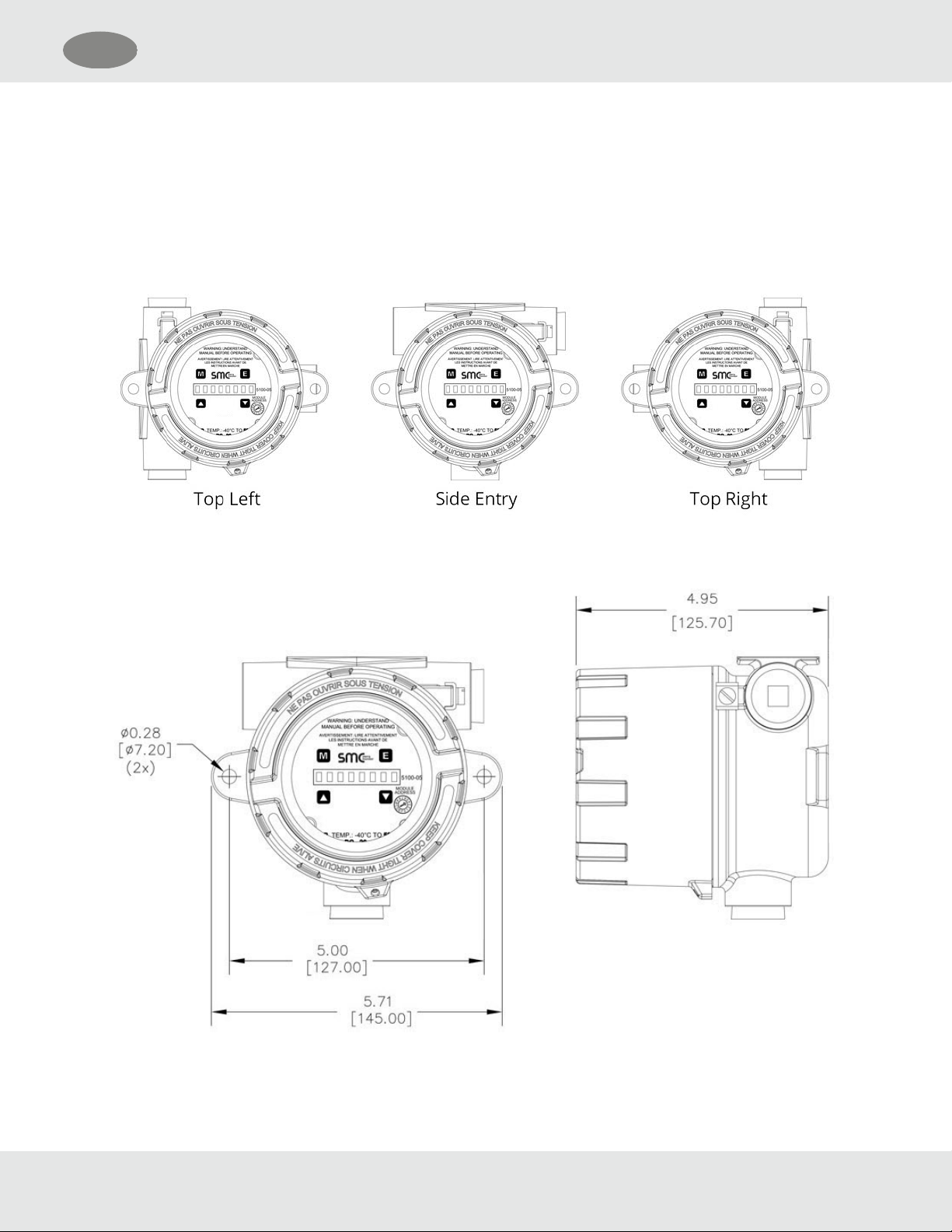
3.1 Transmitter Locations
Select locations for each transmitter so that they are placed in areas accessible for calibration.
3.2 Wiring
3.2.1 4-20 mA Analog Output Operation
For a 3-wire non-isolated connection, set jumpers, located on the bottom of the transmitter board, to the lower position as
illustrated in Section 3.5 Module Address Switch. Verify that both jumpers are in the position marked by 3-wire. When using
a 3-wire connection, a minimum of an 18 AWG, 3-conductor shielded cable must be used. A cable shield must never be
used as a conductor. Larger gauge wire is recommended with distances over 1000’. Connect wires as shown in Section 3.5
Module Address Switch.
For a 4-wire isolated connection, set jumpers, located on the bottom of the transmitter board, to the upper position as
illustrated in Section 3.5 Module Address Switch. Verify that both jumpers are in the position marked by 4-wire. When using
a 4-wire connection, a minimum of 2 each of an 18 AWG, 2 conductor twisted/shielded pair cable must be used. A cable
shield must never be used as a conductor. Larger gauge wire is recommended with distances over 1000’. Connect wires as
shown in Section 3.5 Module Address Switch.
3.2.2 4-20 mA Analog Input
When using a 2-wire connection, a minimum of an 18AWG, 2 conductor shielded cable must be used. A cable shield must
never be used as a conductor. Larger gauge wire is recommended with distances over 1000'. Connect wires as shown in
Section 3.5 Module Address Switch.
3.2.3 Modbus Operation Using RS-485 Connection
Use a minimum of 18 AWG, 2-conductor for DC power connection. No shield required. In addition, use a minimum of 24
AWG, low capacitance, shielded data cable for RS-485 half-duplex communication. The installation may be planned in a
manner which provides up to 32 sensor modules on a single home run.
Standard default RS-485 Settings are: 38,400 baud, 8 bits, 1 stop bit, no parity
Termination Resistor Jumper
Termination resistors are used in RS-485 wire runs to provide impedance matching. The IT series modules use a 120 Ohm
resistor for this function. The cable being used for this RS-485 connection must have a minimum of 100 Ohm impedance
with a maximum of 120 Ohms.
Installations where the cable length is under 100’, termination resistors may not be required. In installations where the cable
length is greater than 100’, it is recommended to place the termination jumpers on the first device and last device on the
RS-485 wire run. Termination jumper must be removed from all other modules connected between the first and last device.
The first device in the RS-485 multiplexed bus is usually a gas controller or PLC. Factory TERM resistor setting is “not
enabled.”
Bias Jumpers (BIAS A, BIAS B)
Bias resistors are used to force RS-485 receiver outputs to a known (fail-safe) state, when the bus is idle. Bias jumpers are
always installed in pairs as the bias must be placed on both the TX A and TX B lines. The IT series of toxic gas sensors
automatically apply the bias jumpers, and are factory installed so that the bias is always enabled.
SMC 5100-99-IT Transmitter 10
3 Installation US