Valex M-SMA 18 -MULTI ONE User manual

- 1 -
Smerigliatrice angolare a batteria M-SMA 18 -MULTI ONE
ISTRUZIONI D’USO
Istruzioni originali
Cordless angle grinder M-SMA 18 -MULTI ONE
INSTRUCTION MANUAL
Translation of the original instructions
1429201
10-10-2018
ATTENZIONE! Prima di usare la macchina, leggete e comprendete le istruzioni di sicurezza e le istruzioni d’uso fornite.
CAUTION! Before using the machine, read and understand the supplied safety instructions and operating instructions.

- 2 -
Smerigliatrice angolare a batteria
Cordless angle grinder
a 18 V
b 8500 rpm
c 115 mm
f 22,2 mm
g M14
h 78 dB(A) K=3
i 89 dB(A) K=3
l 3,4 m/s2 K=1,5
m 1600g
DATI TECNICI
a. Tensione
b. Numero di giri a vuoto
c. Diametro massimo disco abrasivo
f. Diametro foro disco abrasivo
g. Attacco albero filettato
h. Livello di pressione acustica LpA
i. Livello di potenza acustica LwA
l. Livello di vibrazioni con trapanatura nel metallo ah, ag
m. Peso
TECHNICAL DATA
a. Voltage
b. No load rpm
c. Maximum abrasive disc diameter
f. Abrasive disc hole diameter
g. Threaded shaft connection
h. Acoustic pressure level LpA
i. Acoustic power level LwA
l. Vibration emission, drilling in metal ah, ag
m. Weight
DICHIARAZIONE DI CONFORMITA’
La ditta indicata in etichetta dichiara sotto
la propria responsabilità che il prodotto ivi
citato è conforme ai requisiti essenziali di
sicurezza e salute contenuti nelle seguenti
direttive europee:
2006/42/CE, 2014/30/CE, 2011/65/CE
DECLARATION OF CONFORMITY
The firm indicated on the label declares, under
its own responsibility, that the product cited
there complies with the essential health and
safety requirements contained in the following
European directives:
2006/42/EC, 2014/30/EC, 2011/65/EC
Persona autorizzata a costituire il fascicolo tecni-
co presso/ The person authorized to compile
the technical file is in
Valex SpA - Via Lago Maggiore 24
36015 Schio (VI) - Italy
Schio, 05-2018
Un procuratore - Attorney
SMIDERLE STEFANO
M-SMA 18
MULTI ONE

- 3 -
A
B C
2 1
15
13
10
9
8
14
25
7
26
25
3
12
5
611
8
9
90°
Avvitare
Svitare
90°
b
a
NL
32
41

- 4 -
D
E
a
b
8
1

- 5 -
i
SIMBOLOGIA
Osservate con attenzione la simbologia della fig.B e memorizzate il
rispettivo significato. Una corretta interpretazione dei simboli consente
un uso più sicuro della macchina.
1 Modello macchina
2 Dati tecnici
3 Numero di lotto (le prime 2 cifre del lotto indicano l’anno di co-
struzione)
4 Marchi di certificazione
V Volt
Hz Hertz
~ corrente alternata
Corrente continua
W Watt
mm millimetri
m metri
s secondi
kg chilogrammi
novelocità a vuoto
min-1 giri al minuto
dB decibel
Vi ringraziamo per averci preferito nella scelta di questo utensile elet-
trico, di seguito chiamato smerigliatrice angolare.
ATTENZIONE! La smerigliatrice angolare è idonea, con l’utilizzo di
opportuni dischi, alle operazioni di molatura, levigatura, spazzolatura
a filo metallico, lucidatura e di taglio abrasivo di vari materiali come
metallo, legno, plastica e laterizio a secco.
E’ vietato l’utilizzo di materiali pericolosi e in ambienti con pericolo
di incendio/esplosione.
Questo istruzioni riportano le informazioni e quanto ritenuto necessario per
il buon uso, la conoscenza e la normale manutenzione dell’utensile. Esse
non riportano le informazioni sulle tecniche di lavorazione dei vari materiali;
l’utilizzatore troverà maggiori notizie su libri e pubblicazioni specifiche o
partecipando a corsi di specializzazione.
COMPONENTI
Fare riferimento alla fig. A e seguenti, allegate alle presenti istruzioni.
1. Alloggiamento batteria
2. Impugnatura principale
3. Interruttore avvio/arresto
5. Pulsante bloccaggio albero portadisco
6. Scatola ingranaggi
7. Albero portadisco
8. Flangia portadisco
9. Flangia bloccadisco
10. Disco abrasivo (non incluso)
11. Chiave bloccaggio disco
12. Sede per impugnatura laterale
13. Impugnatura laterale
14. Protezione
15. Feritoie di ventilazione
25. Leva di serraggio protezione
INSTALLAZIONE
ATTENZIONE! La Ditta costruttrice declina ogni responsabilità
per gli eventuali danni diretti e/o indiretti causati da un errato
allacciamento.
ATTENZIONE! Prima di effettuare le seguenti operazioni assi-
curatevi che la batteria sia scollegata dall’apparecchio.
TRASPORTO
Per trasportare l’utensile utilizzate sempre il suo imballo o la sua va-
ligetta (se presente); questo lo preserverà da urti, polvere e umidità
che ne possono compromettere il regolare funzionamento.
Durante il trasporto togliete il disco abrasivo/spazzola ecc. dalla
macchina.
MOVIMENTAZIONE
Afferrate saldamente l’impugnatura (pos.2) senza azionare l’inter-
ruttore, mantenete l’utensile lontano dal vostro corpo e dopo l’uso
appoggiatelo senza battere e senza colpire il disco.
MESSA IN SERVIZIO
Nel luogo che utilizzerete l’utensile elettrico è opportuno considerare:
-che la zona non sia umida e sia al riparo dagli agenti atmosferici.
-che attorno sia prevista un’ampia zona operativa libera da impedimenti.
-che vi sia una buona illuminazione.
-che sia utilizzata in vicinanza dell’interruttore generale con differen-
ziale.
-che l’impianto di alimentazione sia dotato di messa a terra conforme
alle norme (solo se l’utensile elettrico è di classe I, cioè dotato di
spina con cavo di terra).
-che la temperatura ambiente sia compresa tra 10° e 35° C.
-che l’ambiente non sia in atmosfera infiammabile/esplosiva.
Estraete la macchina ed i componenti e verificate visivamente la loro
perfetta integrità; a questo punto procedete ad una accurata pulizia per
togliere gli eventuali oli protettivi dalle superfici metalliche.
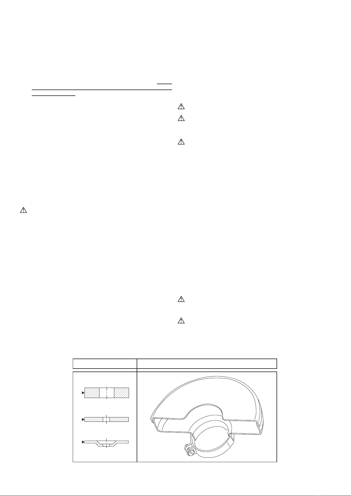
MONTAGGIO PROTEZIONE IN DOTAZIONE CON LA SMERIGLIATRICE
(fig.C, pos.14)
ATTENZIONE! Ad una determinata protezione possono essere
installati solo alcuni tipi di dischi abrasivi; osservate anche le
informazioni del capitolo “ISTRUZIONI D’USO – Protezione disco”
delle pagine seguenti.
1 Allentate l’anello della protezione tirando verso l’esterno la leva di
serraggio (pos.25).
2 Inserite la protezione (pos.14) nella sede della coppia conica
(pos.26)
3 Ruotate la protezione nella posizione indicata in fig.A (protezione
rivolta verso l’impugnatura principale).
4 Fissate nuovamente la leva di serraggio.
5 Assicuratevi che il dispositivo di protezione sia ben fissato.
Attenzione: La posizione della protezione può venire adattata alle
specifiche condizioni di lavoro. Allentate la leva di serraggio (pos.25)
e ruotate la protezione in modo da tenere lontani dal corpo i residui
della lavorazione e proteggere le mani
MONTAGGIO IMPUGNATURA LATERALE (pos.13)
L’impugnatura laterale può essere montata su più lati dove è presente
il foro filettato (pos.12); di norma viene fissata sul lato sinistro per im-
pugnarla con la mano sinistra, ma può essere montata nella posizione
a voi più favorevole (es. per mancini). Inseritela nel foro filettato della
macchina e avvitatela bene a fondo.
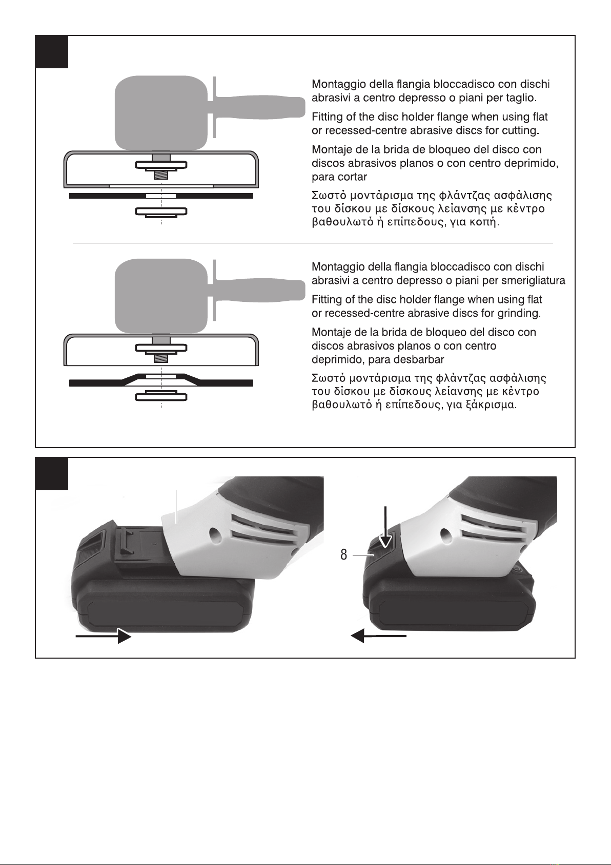
MONTAGGIO DISCO ABRASIVO (pos.10, non incluso)
1) Verificate che il senso di rotazione del disco corrisponda a quello
della smerigliatrice.
2) Capovolgete la smerigliatrice.
3) Verificate che il diametro della sede della 2 flange e il foro del disco
siano della stessa dimensione; a tale scopo è utile misurare con un
calibro (non incluso) e leggere i dati tecnici.
4) Bloccate momentaneamente la rotazione dell’albero motore pre-
mendo il pulsante (pos.5) e svitate la flangia bloccadisco (pos.9).
Non smontate la flangia portadisco (pos.8).
5 Infilate il disco abrasivo (pos.10) sull’albero (pos.7) ed appoggiatelo
alla flangia portadisco (pos.8). Fate attenzione che la battuta della
flangia portadisco entri nel foro del disco.
6) Osservate la figura D per il corretto posizionamento della flangia
bloccadisco (pos.9) in funzione dei dischi che intendete utilizzare.
Avvitate la flangia bloccadisco (pos.9) e fissatela bene usando la
chiave di fissaggio (pos.11); durante il fissaggio mantenere premuto

- 6 -
il pulsante di bloccaggio albero (pos.5). La chiave di fissaggio va
inserita con i due perni nei fori della flangia bloccadisco.
7) Ruotate a mano e controllate che il disco sia ben centrato e ben
serrato dalle flange.
8) Mantenendo la smerigliatrice lontano dal corpo effettuate una prova
di funzionamento a vuoto per 1 minuto.
RIMONTAGGIO DELLE FLANGE (pos.8-9)
Nel caso entrambe le flange siano state rimosse, prestare attenzione
alla sequenza di rimontaggio:
1. Infilare la flangia portadisco (pos.8) nell’albero filettato; questa
flangia ha una sede sagomata che deve accoppiarsi con la
sagoma dell’albero.
2. Avvitare la flangia bloccadisco (pos.9) nell’albero filettato.
MONTAGGIO DEL PLATORELLO PER LUCIDARE E SMERIGLIARE
(pos.19, se presente)
1) Capovolgete la smerigliatrice.
2) Bloccate momentaneamente la rotazione dell’albero motore pre-
mendo il pulsante (pos.5), svitate la flangia bloccadisco (pos.9),
sfilate la flangia portadisco (pos.8) e riponete le flange a parte.
3) Avvitate a mano e a fondo il platorello (pos.19); durante il fissaggio
mantenere premuto il pulsante di bloccaggio albero (pos.5).
4) Applicate sul velcro del platorello e al centro, il disco di carta per
smerigliare (pos.20) o il disco in tessuto per lucidare (pos.21).
5) Ruotate a mano e controllate che il platorello/disco siano ben
centrati e ben serrati.
6) Mantenendo la smerigliatrice lontano dal corpo effettuate una prova
di funzionamento a vuoto per 1 minuto.
MONTAGGIO DELLA SPAZZOLA ROTATIVA (pos.22, se presente)
ATTENZIONE! Indossate guanti a protezione delle mani.
1) Capovolgete la smerigliatrice.
2) Bloccate momentaneamente la rotazione dell’albero motore pre-
mendo il pulsante (pos.5), svitate la flangia bloccadisco (pos.9),
sfilate la flangia portadisco (pos.8) e riponete le flange a parte.
3) Avvitate la spazzola (pos.22) a fondo usando la chiave (pos.23);
durante il fissaggio mantenere premuto il pulsante di bloccaggio
albero (pos.5).
4) Ruotate a mano e controllate che la spazzola sia centrata e ben
serrata.
6) Mantenendo la smerigliatrice lontano dal corpo effettuate una prova
di funzionamento a vuoto per 1 minuto.
CARICA DELLA BATTERIA (Seguire le istruzioni allegate al
caricabatterie)
ATTENZIONE! Prima di utilizzare la smerigliatrice è necessario
effettuare una carica completa della batteria.
ATTENZIONE! Ricaricare soltanto con un caricabatterie previsto
per questo tipo di apparecchio. Un caricabatterie che è adeguato
per un tipo di gruppo di batterie può creare un rischio di incendio
quando viene utilizzato con altri gruppi di batterie.
Per mantenere efficiente la batteria, non scaricarla completamente.
Eseguite una successiva ricarica completa:
- Dopo ogni utilizzo.
- Almeno ogni 4 mesi, anche in caso di inutilizzo.
- Se durante il lavoro notate un calo evidente delle prestazioni dell’ap-
parecchio.
INSERIMENTO E RIMOZIONE DELLA BATTERIA ( fig.E)
- Inserite la batteria attraverso le guide presenti sull’alloggiamento
batteria. (pos.1)
- Estraete la batteria dalla sede dell’utensile agendo sul dispositivo di
sgancio (pos.8)
AVVIAMENTO, ARRESTO (FIG.A)
ATTENZIONE! Prima di avviare l’utensile elettrico è obbligatorio
indossare i dispositivi di protezione individuale (non inclusi).
ATTENZIONE! Prima dell’avviamento e durante la fase di lavoro,
afferrare saldamente la smerigliatrice con entrambe le mani
nelle impugnature senza mai abbandonare la presa, in modo tale
che, in caso di pericolo, possiate arrestarla immediatamente.
ATTENZIONE! Durante l’utilizzo fate in modo che nessuno si
avvicini alla vostra zona di lavoro.
- Inserire la batteria carica nell’ alloggiamento dell’apparecchio (Pos.1).
- La smerigliatrice angolare è dotata di un interruttore di sicurezza.
- Per avviare l‘apparecchio spingete verso destra e poi in avanti l‘in-
terruttore avvio/arresto (pos.3).
- Per spegnere la smerigliatrice angolare premete la parte posteriore
dell‘interruttore. L‘interruttore ritorna alla posizione di partenza
Vi consigliamo di ripetere queste operazioni alcune volte prima di ini-
ziare il lavoro in modo da familiarizzare il più possibile con i comandi.
Se osservate delle anomalie di funzionamento spegnete l’utensile
elettrico e consultate il capitolo “Problemi, cause e rimedi”.
Quando non lavorate spegnete e staccate la spina dalla presa.
ISTRUZIONI D’USO
Dopo aver letto attentamente i capitoli precedenti, seguite scrupolo-
samente questi consigli che vi permetteranno di ottenere il massimo
delle prestazioni.
Procedete con calma in modo da prendere familiarità con tutti i co-
mandi; solo dopo aver acquisito una buona esperienza riuscirete a
sfruttarne a fondo tutte le potenzialità.
PROTEZIONE DISCO
ATTENZIONE! La Ditta costruttrice declina ogni responsabilità
per gli eventuali danni diretti e/o indiretti causati da un errato/
mancato utilizzo della protezione in dotazione o l’utilizzo di
protezioni non conformi.
ATTENZIONE! E’ vietato l’utilizzo della smerigliatrice senza la
protezione.
A seconda del tipo di disco che andrete a montare è necessario in-
stallare prima la protezione adatta, in modo da proteggere al meglio
l’operatore da schegge, scintille o scoppio del disco.
Osservate la tabella seguente ed agite di conseguenza.
OPERAZIONE E TIPO MOLA PROTEZIONE
Taglio
Mola piana
Mola troncatrice piana
Mola troncatrice a centro depresso ≥ 175°
Protezione su 3 lati

- 7 -
DISCHI ABRASIVI
Acquistate dischi abrasivi di qualità, con diametro esterno massimo
indicato nei dati tecnici della smerigliatrice, con foro idoneo alle carat-
teristiche della flange, idonei alla velocità massima della smerigliatrice e
adatti al materiale da lavorare. Rivolgetevi al vostro rivenditore di fiducia
che potrà consigliarvi al meglio. La nostra azienda produce un’ampia
gamma di accessori adatti ai più svariati impieghi.
I dischi durante l’uso si usurano, si danneggiano, si sbilanciano,
scadono dopo una certa data: effettuate sempre un controllo visivo
prima dell’uso e se necessario sostituiteli.
Per montaggio e sostituzione vedere sopra il capitolo “INSTALLAZIONE
– Montaggio disco abrasivo”.
Maneggiate e conservate con cura i dischi, non esponendoli a urti,
flessione, compressione, umidità, alte o basse temperature, luce
solare diretta.
USO
ATTENZIONE! E’ vietato l’utilizzo della smerigliatrice con una
sola mano.
Indossate i dispositivi di protezione individuale elencati nel cap. Av-
vertenze.
Il pezzo in lavorazione deve essere sempre saldamente fissato al
banco di lavoro, con una morsa o altro, specialmente con i pezzi
piccoli e leggeri.
Impugnate l’utensile con entrambe le mani. Il cavo di alimentazione
deve essere tenuto lontano dalle parti rotanti e dal vostro corpo.
Dopo aver montato l’accessorio, avviate l’utensile mantenendolo lon-
tano dal vostro corpo. Quando acceso movimentatelo con prudenza,
in quanto una disattenzione potrebbe causarvi ferite anche gravi;
perciò mantenete lontano dalla zona di lavoro gli estranei, i bambini
e gli animali.
La normale posizione dell’operatore è con braccia distese in avanti,
smerigliatrice diritta con disco verso avanti e protezione del disco
OPERAZIONE E TIPO MOLA PROTEZIONE
Smerigliatura
Mola a centro depresso
Mola a centro depresso semiflessibile
IN DOTAZIONE CON
LA SMERIGLIATRICE
≥ 175°
Protezione su 2 lati
OPERAZIONE E TIPO MOLA PROTEZIONE
Smerigliatura
Mola a tazza cilindrica
Mola a tazza conica
≥ 240°
Protezione su 2 lati
Regolabile con lo spesso-
re della mola
verso l’operatore.
A contatto con il pezzo la smerigliatrice tenderà a spostarsi lateralmente
con una forza proporzionale alla pressione che eserciterete sulla su-
perficie in lavoro; contrastate questa azione in modo da mantenere in
posizione la smerigliatrice. Inoltre è sempre possibile un contraccolpo
improvviso, vedere il cap. “Avvertenze” per prevenirlo e contrastarlo.
A seconda del tipo di lavorazione operate sul pezzo con attenzione e
procedete gradualmente senza forzare troppo nell’azione. Una pres-
sione eccessiva sul pezzo potrebbe causare la rottura dell’accessorio
e del pezzo con lancio improvviso di piccoli frammenti contro di voi;
inoltre l’utensile elettrico sarà sollecitato maggiormente e la sua durata
sarà breve fino al mancato funzionamento. Evitate di avvicinare il viso
alla zona di lavoro e mantenete sempre una certa distanza di sicurezza.
Nelle operazioni di smerigliatura e su pezzi metallici si genererà un
fascio di scintille lungo anche diversi metri; questo potrebbe danneg-
giare gli oggetti in zona o provocare un incendio/scoppio a contatto
con elementi infiammabili.
Nelle operazioni di sbavatura mantenete inclinata la smerigliatrice di
15°-20° rispetto la superficie del pezzo.
Nelle operazioni di spazzolatura su superfici verniciate o ossidate si
produrrà un notevole quantità di povere; anche lavorazioni su alcuni
metalli e su alcuni tipi di legno le polveri prodotte sono nocive alla
vostra salute.
Nelle operazioni di levigatura e di lucidatura non premete eccessiva-
mente ma sfruttate solo il peso della smerigliatrice. Per lavorazioni su
superfici verniciate operate sempre con cautela per non rigare la super-
ficie; si consiglia di effettuate prima una prova su una zona nascosta.
Al termine spegnete l’utensile, appoggiatelo al banco e togliete la bat-
teria. Non arrestare la rotazione contro il pezzo, ma attendere l’arresto

- 8 -
prima di posare la smerigliatrice.
MANUTENZIONE
ATTENZIONE! Prima di ogni controllo o regolazione togliete la
batteria dall’apparecchio.
ATTENZIONE! Non manomettete o tentate di riparare l’utensile
elettrico.
ATTENZIONE! Una eventuale revisione interna manutenzione,
deve essere effettuata solo da un centro assistenza autorizzato.
La durata e il costo d’esercizio dipendono anche da una costante e
scrupolosa manutenzione.
Pulite regolarmente ed abbiate cura del vostro utensile elettrico, vi
garantirete una perfetta efficienza ed una lunga durata dello stesso.
- Rimuovete la polvere e i residui di lavorazione con uno straccio e un
pennello a setole morbide.
- Non spruzzate o bagnate d’acqua l’utensile elettrico, pericolo di
infiltrazioni interne.
- Non usate infiammabili, detergenti o solventi vari.
- Le parti in plastica sono aggredibili da agenti chimici.
- Non utilizzate un getto d’aria compressa per la pulizia: pericolo lancio
materiale!
- Prestate particolare attenzione alla pulizia dell’interruttore, alle feritoie
di ventilazione del motore, alle impugnature.
PROBLEMI, CAUSE E RIMEDI
PROBLEMA CAUSE RIMEDI
L’utensile
elettrico non
si avvia
Interruttore in posizio-
ne OFF “O”
Azionare l’interruttore in po-
sizione acceso “I”
Batteria scarica Effettuare una ricarica com-
pleta alla batteria
Batteria non inserita
correttamente nell’al-
loggiamento dell’u-
tensile
Sganciate la batteria e inse-
ritela correttamente
La batteria è surriscal-
data ed è intervenuta
la protezione interna
autoripristinabile
Attendere che la batteria si
raffreddi
Utensile elettrico o
batteria guasti
Sostituite la batteria o/e ri-
volgetevi ad un centro di
assistenza autorizzato
L’utensile
elettrico vi-
bra molto
Accessorio danneg-
giato o sbilanciato
Sostituire l'accessorio
Accessorio montato in
modo errato
Smontare l'accessorio, pulire
i componenti e rimontare
seguendo le istruzioni
La batte-
ria non si
ricarica
Batteria non inseri-
ta correttamente
nell’alloggiamento del
caricabatterie
Sganciate la batteria e inse-
ritela correttamente
Caricabatteria o bat-
teria non pronto per
la carica.
Batteria surriscaldata.
Attendere che la batteria si
raffreddi
Caricabatterie o batte-
ria guasti
Sostituite la batteria o/e ri-
volgetevi ad un centro di
assistenza autorizzato
La smeri-
gliatrice si
arresta du-
rante una
fase di lavo-
razione
Batteria scarica Se disponibile inserire un
nuova batteria carica, oppure
sganciare la batteria ed effet-
tuare una ricarica completa.
La batteria è surriscal-
data ed è intervenuta
la protezione interna
autoripristinabile
Attendere che la batteria si
raffreddi
Intervento del disposi-
tivo di protezione che
limita la corrente
Ridurre la pressione eserci-
tata sul pezzo in lavorazione
ATTENZIONE! Se dopo aver eseguito gli interventi sopra de-
scritti l’utensile elettrico non funziona correttamente o in caso di
anomalie diverse da quelle indicate, portatelo presso un centro di
assistenza autorizzato esibendo la prova di acquisto e richiedendo
ricambi originali. Fate sempre riferimento alle informazioni riportate
sull’etichetta dati tecnici.
IMMAGAZZINAMENTO
Effettuate una accurata pulizia di tutta la macchina e sue parti acces-
sorie (vedi paragrafo Manutenzione). Proteggete le parti non verniciate
con un olio protettivo ed utilizzate l’imballo originale o la valigetta (se
presente) per proteggerla.
Riponete la macchina lontano dalla portata dei bambini, in posizione
stabile e sicura. Il luogo dovrà essere asciutto, privo da polveri, tem-
perato e protetto dai raggi solari diretti.
Al locale di rimessaggio non devono avere accesso i bambini e gli
estranei.
SMALTIMENTO
Per la salvaguardia ambientale procedete secondo le leggi vigenti del
Paese in cui vi trovate. Rivolgetevi alle autorità competenti per maggiori
notizie in merito.
Quando la macchina non è più utilizzabile né riparabile, consegnatela
con l’imballo ad un punto di raccolta per il riciclaggio.
I rifiuti elettrici ed elettronici possono contenere sostanze pericolose
per l’ambiente e la salute umana; non devono pertanto essere smaltiti
con quelli domestici ma mediante una raccolta separata negli appositi
centri di raccolta o riconsegnati al venditore nel caso di acquisto di
una apparecchiatura nuova analoga. Lo smaltimento abusivo dei rifiuti
comporta l’applicazione di sanzioni amministrative.
Smaltimento batterie: Le batterie incluse nell’apparecchio
possono essere smaltite assieme ad esso.
Non gettate nel fuoco e non disperdete nell’ambiente le batterie
esauste ma consegnatele agli appositi centri per il loro smaltimento.
Non smaltire assieme ai rifiuti domestici.
GARANZIA
Il prodotto è tutelato a norma di legge contro non conformità rispetto
alle caratteristiche dichiarate purché sia stato utilizzato esclusivamente
nel modo descritto dalle istruzioni, non sia stato manomesso in alcun
modo, sia stato conservato correttamente, sia stato riparato da tecnici
autorizzati e, ove previsto, siano stati utilizzati solo ricambi originali.
In caso di utilizzo industriale o professionale oppure in caso di impiego
simile la garanzia ha validità di 12 mesi.
Per emettere una richiesta di intervento in garanzia è necessario
presentare la prova di acquisto al rivenditore o ad centro assistenza
autorizzato.
MODIFICHE
Testi, figure e dati corrispondono allo standard aggiornato all’epoca
della stampa delle presenti istruzioni. Il costruttore si riserva la facoltà
di aggiornare la documentazione qualora venissero apportate delle
variazioni alla macchina, senza incorrere per questo in alcun obbligo.
© Nessuna parte di questa pubblicazione e della documentazione allegata alla
macchina può essere riprodotta senza un permesso scritto.

- 9 -
g
SYMBOLS
Carefully observe the symbols in fig. B and memorise their respective
meanings. Correct interpretation of the symbols allows safer use of
the machine.
1 Machine model
2 Technical data
3 Batch number (the first 2 figures of the batch number indicate the
year of manufacture)
4 Certification markings
V Volt
Hz Hertz
~ alternating current
Direct current
W Watt
mm millimetres
m metres
s seconds
kg kilograms
no no load speed
min-1 revolutions per minute
dB decibel
We thank you for having purchased this power tool that will hereafter
also be referred to as “angle grinder”.
WARNING! The angle grinder is suitable, when used with the
appropriate discs, for the grinding, sanding, wire brushing, polishing
and abrasive cutting of materials such as metal, wood, plastic and
dry bricks.
It is prohibited to use dangerous materials in environments with risk
of fire/explosion
These instructions contain information deemed necessary for correct use,
knowledge and standard tool maintenance. They do not report information
on techniques for working with various materials. The user will find more
information in books and specialised publications or by attending courses.
COMPONENTS
Refer to fig. A and the other figures attached to these instructions.
1. Battery compartment
2. Main handgrip
3. Start/stop switch
5. Disc holder shaft lock button
6. Gear box
7. Disc holder shaft
8. Disc holder flange
9. Disc lock flange
10. Abrasive disc (not included)
11. Disc locking key
12. Seat for lateral handgrip
13. Side handgrip
14. Guard
15. Air vents
25. Guard locking lever
INSTALLATION
WARNING! The manufacturer is not liable for any direct and/or
indirect damage caused by incorrect connections.
WARNING! Before carrying out the following operations, make
sure that the battery is disconnected from the tool.
TRANSPORT
Always use the packaging or case (when provided) when transporting
the tool; this will protect it from impact, dust and humidity which can
compromise normal operation.
During transport, remove the abrasive disc, brush, etc. from the
machine.
HANDLING
Firmly grasp the handgrip (pos. 2) without using the switch; keep
the tool well away from your body and after use place it down gently
without hitting the disc.
SWITCHING ON
When choosing where to use the power tool, the following should be
considered:
- that the place is not damp and is protected from the weather.
- that there is a large working area free from obstacles.
- that there is good lighting.
- that it is used close to the main switch with residual current device.
- that the power supply system is earthed and conforms to the stan-
dards (only if the power tool is class I, which is equipped with an
earth cable plug).
- that the room temperature is between 10° and 35°C.
- that the environment is not in a flammable/explosive atmosphere.
Take out the machine and components and visually check that they
are perfectly intact; then proceed to thoroughly clean them in order to
remove any protective oils from metal surfaces.
ASSEMBLING GUARD PROVIDED WITH THE ANGLE GRINDER (fig.
C, pos.14)
WARNING! Only certain types of abrasive discs can be installed
on a given guard; follow the information provided in the “INSTRUC-
TIONS FOR USE - Disc Guard” chapter in the following pages.
1 Loosen the guard ring by pulling the locking lever outwards (pos.25).
2 Insert the guard (pos.14) into the housing of the bevel gear (pos.26)
3 Rotate the guard into the position indicated in fig.A (guard turned
towards the main handgrip).
4 Fasten the locking lever again.
5 Make sure that the protective device is properly secured.
Warning: The guard’s position can be adapted to specific work condi-
tions. Loosen the locking lever (pos.25) and turn the guard so as to
keep the working residues away from the body and protect the hands
SIDE HANDGRIP ASSEMBLY (pos.13)
The lateral handgrip can be assembled on any side on which there is
a threaded hole (pos.12); it is usually secured on the left in order to
grab hold with the left hand, but it can be assembled in the position
of your preference (e.g. for left-handed people). Insert the handgrip
into the threaded hole of the device and secure by screwing tightly.
ABRASIVE DISC ASSEMBLY (pos.10, not included)
1)Check that the rotation direction of the disc corresponds to that of
the angle grinder.
2)Turn the angle grinder upside down.
3)Check that the diameter of the seat of the 2 flanges and the hole of
the disc are the same size; to this end, it is better to measure using
a gauge (not included) and reading the technical data.
4)Temporarily block the rotation of the motor shaft by pressing the
button (pos.5) and unscrew the disc lock flange (pos.9). Do not
disassemble the disc hold flange (pos.8).
5)Insert the abrasive disc (pos.10) onto the shaft (pos.7) and place
it on the disc hold flange (pos.8). Make sure the disc hold flange
rabbet goes into the disc hole.
6)Follow fig. D to correctly place the disc lock flange (pos.9) depending
on the number of discs you intend to use. Screw the disc block flange
(pos.9) and fix it carefully using the fixture key (pos.11): while doing
so, keep the shaft block button pressed (pos.5). The locking key
should be inserted with the two pins, in the disc lock flange holes.
7)Rotate by hand and check that the disc is well centred and well
secured by the flanges.
8)Keeping the angle grinder away from the body, carry out a dry test
run for 1 minute.

- 10 -
RIMONTAGGIO DELLE FLANGE (pos.8-9)
Nel caso entrambe le flange siano state rimosse, prestare attenzione
alla sequenza di rimontaggio:
1. Infilare la flangia portadisco (pos.8) nell’albero filettato; questa
flangia ha una sede sagomata che deve accoppiarsi con la
sagoma dell’albero.
2. Avvitare la flangia bloccadisco (pos.9) nell’albero filettato.
POLISHING AND GRINDING PAD ASSEMBLY (pos.19, where fitted)
1)Turn the angle grinder upside down.
2)Temporarily block the rotation of the motor shaft by pressing the
button (pos.5), unscrew the disc lock flange (pos.9), remove the
disc hold flange (pos.8) and put the flanges to one side.
3)Tighten by hand and at the base of the pad (pos. 19); during fixing
hold the shaft lock button (pos. 5).
4)Apply the disc of paper for grinding (pos.20) or the fabric polishing
disc (pos.21) on the velcro of the pad and at the centre.
5)Rotate by hand and check that the backing pad/disc is well centred
and well secured.
6)Keeping the angle grinder away from the body, carry out a dry test
run for 1 minute.
ASSEMBLY OF THE ROTATING BRUSH (pos.22, if present)
WARNING! Wear protective gloves.
1)Turn the angle grinder upside down.
2)Temporarily block the rotation of the motor shaft by pressing the
button (pos.5), unscrew the disc lock flange (pos.9), remove the
disc hold flange (pos.8) and put the flanges to one side.
3)Tighten the brush (pos.22) using the key (pos.23); during fixing
hold the shaft lock button (pos. 5).
4)Rotate by hand and check that the brush is well centred and well
secured.
6)Keeping the angle grinder away from the body, carry out a dry test
run for 1 minute.
CHARGING THE BATTERY (Follow the instructions attached to the
battery charger)
WARNING! Before using the angle grinder it is necessary to
fully charge the battery.
WARNING! Recharge only with a battery charger designed for
this type of tool. An inappropriate battery charger can cause a fire
hazard when used with other battery units.
To keep the battery in good working order, do not discharge it
completely.
Fully charge the battery:
- After each use.
- At least every 4 months, even if not used.
- If while working you notice a clear drop in the performance of the tool.
INSERTING AND REMOVING THE BATTERY (fig. E)
- Insert the battery through the guides in the battery compartment.
(pos.1)
- Take out the battery from its housing in the tool by operating the
release device (pos.8)
SWITCHING ON AND OFF
(FIG.A)
WARNING! Before starting the power tool it is compulsory to
wear individual protection equipment (not provided).
WARNING! Before starting the tool and during operation, hold
the tool firmly with both hands, using both handgrips, without
ever letting go, so that you can stop the machine immediately
in the case of danger.
WARNING! Make sure nobody is approaching the working area
during use.
- Insert the charged battery in the compartment in the tool (Pos.1).
- The angle grinder has a safety switch.
- To start the tool, push the on/off switch to the right, then forwards
(pos.3).
- To switch off the angle grinder, press the rear of the switch. The
switch will return to the starting position
We recommend repeating these operations several times before star-
ting work, in order to familiarise yourself with the controls as much
as possible.
If you notice any working defects, switch off the power tool and consult
the chapter “Problems, causes and solutions”.
When not using the tool, turn it off and disconnect the plug from the
socket.
USER INSTRUCTIONS
After reading the previous chapters carefully, apply these tips scrupu-
lously to obtain maximum performance.
Proceed calmly so as to become familiar with all the controls; after
having gained sufficient experience, you will be able to make full use
of its capacities.
DISC GUARD
WARNING! The manufacturer does not accept any liability for
direct and/or indirect damage resulting from the wrong/lack
of use of the protection provided or the use of non compliant
protections.
WARNING! It is forbidden to use the angle grinder without
protection.
Depending on the type of disc to be assembled, first it is necessary
to use appropriate protection, in order to protect the operator from
chips, sparks or explosions of the disc.
Follow the table and act accordingly.
OPERAZIONE E TIPO MOLA PROTEZIONE
Taglio
Mola piana
Mola troncatrice piana
Mola troncatrice a centro depresso ≥ 175°
Protezione su 3 lati

- 11 -
ABRASIVE DISCS
Purchase high quality abrasive discs which have the maximum external
diameter indicated in the technical data of the grinder, a suitable hole
which fits the requirements of the flanges, and which are suitable for
the maximum speed of the grinder and the materials to be processed.
Contact your retailer who will be able to give you the best advice. Our
company produces a wide range of accessories suitable for various
uses.
During use, the discs get worn, become damaged, lose their calibration,
expire after a certain date: always make a visual check before using
and replace if necessary.
For the assembly and replacement, go to the “INSTALLATION - Abrasive
disc assembly” chapter.
Handle and store the discs with care, do not subject them to impact,
bending, compression, moisture, high or low temperatures, and direct
sunlight.
USE
WARNING! It is forbidden to use the angle grinder with only
one hand.
Wear the personal protective equipment listed in the “Warnings”
chapter.
The workpiece must always be firmly secured to the workbench, using
a vice or other device, especially when working on small, lightweight
pieces.
Hold the device with both hands. The power cord must be kept far
from the rotating parts and from your body.
After assembling the accessory, start the tool keeping it far from your
body. When the tool is turned on, handle with caution, as any care-
lessness may cause even serious injury; therefore keep unauthorised
persons, children and pets away from the work area.
The correct position of the operator is with arms stretched forward,
the angle grinder straight with the disc facing forward and the disc
guard facing the operator.
When in contact with the part, the angle grinder will tend to move la-
terally with a force which is proportional to the pressure you will exert
OPERAZIONE E TIPO MOLA PROTEZIONE
Smerigliatura
Mola a centro depresso
Mola a centro depresso semiflessibile
IN DOTAZIONE CON
LA SMERIGLIATRICE
≥ 175°
Protezione su 2 lati
OPERAZIONE E TIPO MOLA PROTEZIONE
Smerigliatura
Mola a tazza cilindrica
Mola a tazza conica
≥ 240°
Protezione su 2 lati
Regolabile con lo spesso-
re della mola
on the work surface; contrast this movement in order to keep the angle
grinder in position. Furthermore, unexpected kickbacks are always
possible. See the “Warnings” chapter to prevent and contrast this.
Depending on the type of process, perform on the part carefully and
proceed gradually without making forceful movements. Excessive
pressure on the part could cause the accessory to break and tiny
fragments may unexpectedly be launched in your direction; in addition,
the power tool will be put under even more strain and it will not have
a long life span or may stop functioning. Avoid getting your face too
close to the work area and always keep a certain safety distance.
When using the angle grinder on metal parts, sparks may fly; this could
damage nearby objects or cause a fire/explosion if put in contact with
flammable elements.
When performing trimming operations, keep the angle grinder inclined
at 15°-20° against the surface on the workpiece.
Brushing on painted or oxidised surfaces, will produce a large quantity
of dust, even when working on metals and certain types of wood. The
dust is harmful to your health.
When sanding or polishing, do not apply excessive pressure, simply
use the weight of the angle grinder. When working on painted surfaces,
always proceed with caution in order no to scratch the surface; it is
advisable to perform a test on a part which is not highly visible.
Once you have finished, switch off the tool, place it on the bench and
remove the battery. Do not switch off the device while it is rotating
against the part; wait for it to stop rotating before placing it on the table.

- 12 -
MAINTENANCE
WARNING! Before any checks or adjustment take the battery
out of the tool.
WARNING! Do not tamper or attempt to repair the power tool.
WARNING! Any internal overhaul or maintenance must only be
performed by an authorised service centre.
The working life and costs also depend on constant and meticulous
maintenance.
Take good care of your power tool and clean it regularly. In this way
its good working order will be ensured and its lifespan extended.
- Remove dust and machining residuals with a cloth or a brush with
soft bristles.
- Do not wet or spray water over the power tool - risk of internal
infiltrations.
- Do not use any flammables, detergents or solvents.
- The plastic parts can easily be damaged by chemical agents.
- Do not use compressed air for cleaning: risk of ejecting material!
- Be careful when cleaning the switch, motor air vents and handgrips.
PROBLEMS, CAUSES AND SOLUTIONS
PROBLEM CAUSES SOLUTIONS
The power
tool fails to
start
ISwitch in the OFF “O”
position
Flip the switch to the ON “I”
position
Flat battery Fully charge the battery
Battery not correctly
inserted in the tool
housing
Take out the battery and
insert it correctly
The battery has
overheated and the
internal auto reset pro-
tection has cut in
Wait for the battery to cool
down
Power tool or battery
faulty
Replace the battery and/or
contact an authorised ser-
vice centre
The power
tool vibrates
a lot
Damaged or unbalan-
ced accessory
Substitute the accessory
Incorrectly assembled
accessory
Disassemble the accessory,
clean the components and
reassemble according to the
instructions
The battery
does not
charge
Battery not correctly
inserted in the battery
charger housing
Take out the battery and
insert it correctly
Battery charger or
battery not ready for
charging. Battery is
overheated.
Wait for the battery to cool
down
Battery charger or bat-
tery faulty
Replace the battery and/or
contact an authorised ser-
vice centre
The an-
gle grinder
stops while
working
Flat battery If available insert a new
charged battery, or take out
the battery and fully charge it.
The battery has
overheated and the
internal auto reset pro-
tection has cut in
Wait for the battery to cool
down
The protective devi-
ce that limits current
tripped
Reduce the pressure applied
to the workpiece
WARNING! If the power tool still fails to operate correctly after
you have carried out the above operations, or in the event of ano-
malies other than those described above, take it to an authorised
service centre with proof of purchase and ask for original spare
parts. Always refer to the information shown on the technical data
label.
STORAGE
Clean the machine and all its accessories thoroughly (see Maintenance
section). Protect the unpainted parts with protective oil and use the original
packaging or case (where fitted) to protect it.
Store the machine in a stable and safe position out of the reach of children. The
place must be dry, free from dust, temperate and protected from direct sunlight.
Keep children and unauthorised personnel out of the storage room.
DISPOSAL
In order to protect the environment, proceed according to the local
laws in force. Contact the relevant authorities for more information.
When the machine is no longer usable or repairable, take the machine
and its packaging to a recycling centre.
Electric and electronic waste may contain substances hazardous
to the environment and human health. It should therefore not be di-
sposed of with household waste, but by means of separate collection
at special collection centres or returned to the vendor in the event of
purchasing a new similar tool. Illegal disposal of waste will result in
administrative sanctions.
Battery disposal: The batteries included in the equipment can be
disposed of along with it.
Do not dispose of used batteries in fire and do not dispose of them
in the environment, but take them to special disposal centres. Do
not dispose of them with domestic waste.
WARRANTY
The product is protected by law against all non-conformities with regard
to its stated characteristics, provided that it has been used solely in the
way described in these user’s instructions, it has not been tampered
with in any way, it has been stored correctly, it has been repaired by
authorised personnel and, where necessary, only original spare parts
have been used.
In the event of industrial or professional use or similar, the warranty is
valid for 12 months.
To issue a request for intervention covered by warranty, proof of purchase
must be shown to the retailer or authorised service centre.
AMENDMENTS
The text, figures and data correspond to the standards in place on the
date of printing the instructions contained herein. The manufacturer
reserves the right to update the documentation if changes are made to
the power tool, without being bound by any obligations.
© No part of this publication and the documentation enclosed with
the machine may be reproduced without written permission from the
manufacturer.
Table of contents
Languages:
Other Valex Grinder manuals