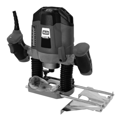
Valex F1300C User manual

F1300C
S467017
23.02.2018
Final dimension: A5
Fresatrice verticale
ISTRUZIONI D’USO
Istruzioni originali
Router
OPERATING INSTRUCTIONS
Translation of the original instructions
ATTENZIONE! Prima di usare la macchina, leggete e comprendete le istruzioni di sicurezza e le istruzioni d’uso fornite
WARNING! Before using the machine, read and understand the supplied safety instructions and operating instructions

- 2 -

- 3 -
a
C
B
VALEX - 36015 SCHIO (VI) - ITALY
MADE IN P.R.C.
3
2
4
1
b
Avvitare
Screw
Svitare
Unscrew
15
20

- 4 -
E
D
2 viti
2 screws
11

- 5 -
E
D
2 viti
2 screws
11

- 6 -
DATI TECNICI
1 Tensione e frequenza nominale
2 Potenza nominale
3 Velocità a vuoto min-max
4 Diametro pinza mandrino
5 Diametro fresa max
6 Pressione acustica LpA
7 Potenza acustica LwA
8 Vibrazioni ah
9 Peso netto
TECHNICAL DATA
1 Voltage and nominal frequency
2 Rated power
3 No-load speed min-max
4 Diameter collet chuck
5 Maximum diameter of cutter
6 Acoustic pressure LpA
7 Acoustic power LwA
8 Vibrations ah
9 Net weight
DICHIARAZIONE DI CONFORMITA’
La ditta indicata in etichetta dichiara sotto la
propria responsabilità che il prodotto ivi citato
è conforme ai requisiti essenziali di sicurezza e
salute contenuti nelle seguenti direttive europee:
2006/42/CE, 2014/35/CE, 2014/30/CE, 2011/65/CE
DECLARATION OF CONFORMITY
The firm indicated on the label declares, under
its own responsibility, that the product cited
there complies with the essential health and
safety requirements contained in the following
European directives:
2006/42/EC, 2014/35/EC, 2014/30/EC, 2011/65/EC
Persona autorizzata a costituire il fascicolo tecnico
presso
The person authorized to compile the technical
file is in
Valex SpA - Via Lago Maggiore, 24
36015 Schio (VI) - Italy
07.2017
Un procuratore - Attorney
SMIDERLE STEFANO
1 230V~50 Hz
2 1300 W
3 11000 - 30000 min-1
4 ø 6 mm - ø 8 mm
5 ø 32 mm
6 88,9 dB(A) K=3
7 99,9 dB(A) K=3
8 2,82 m/s2K=1,5
9 2,8 kg

- 7 -
i
ATTENZIONE! Prima di usare questo
utensile elettrico, leggete ed applicate atten-
tamente le norme di sicurezza e le istruzioni
di seguito riportate. Prima di iniziare il lavoro
assicurateVi, in caso di emergenza, di saper
arrestare l’utensile. L’ uso improprio della
fresatrice può provocare gravi ferite.
ATTENZIONE! Conservate con cura ed a
portata di mano queste istruzioni in modo da
poterle consultare in caso di necessità.
ATTENZIONE! La fresatrice è idonea per
eseguire fori, intagli, bordi e tenonature su
legno. Ogni altro impiego, diverso da quello
indicato in queste istruzioni, può recare danno
all’ utensile e costituire serio pericolo per l’
utilizzatore.
SIMBOLOGIA
Osservate con attenzione la simbologia della
fig.B e memorizzate il rispettivo significato. Una
corretta interpretazione dei simboli consente un
uso più sicuro della macchina.
1 Dati tecnici
2 Doppio isolamento elettrico
3 Numero di lotto
4 Marcatura di conformità CE
V Volt
Hz Hertz
~ corrente alternata
W Watt
kg chilogrammi
mm millimetri
s secondi
n0velocità a vuoto
min-1 corse al minuto
dB decibel
DESCRIZIONE (FIG.A)
1 Corpo motore
2 Impugnature
3 Regolatore velocità mandrino
4 Interruttore
5 Leva bloccaggio spostamento corpo motore
e fresa
6 Volantino fissaggio fermo di profondità
7 Volantino regolazione asta profondità
8 Staffa per fresatura parallela
9 Asta graduata profondità di fresatura
10 Base
11 Adattatore di aspirazione
12 Led presenza alimentazione elettrica
13 Spina per fresatura circolare
14 Dispositivo copiatore
15 Mandrino a pinza
16 Frese utensili (se presenti)
17 Pulsante di sicurezza
18 Chiave/i di servizio
19 Torretta regolazione profondità
20 Pulsante bloccaggio rotazione
21 Feritoie di ventilazione
22 Spina e cavo di alimentazione
MESSA IN SERVIZIO
ATTENZIONE! Durante il montaggio o la
sostituzione di accessori staccate la spina
dalla presa di corrente.
Prima della messa in servizio dell’ uten-
sile controllate la dotazione, l’ integrità della
macchina e di ogni accessorio.
Per le seguenti operazioni è necessario
indossare sempre guanti di protezione.
MONTAGGIO/SMONTAGGIO FRESA
- Con un dito premere il pulsante blocca albero e
con la chiave in dotazione allentare il dado (fig.
C). Inserire il mandrino da 6 o 8 mm, inserire
la fresetta e stringere bene il dado.
AVVIAMENTO
Attenzione! Dopo lo spegnimento la fresa-
trice continua a girare per qualche secondo.
Non appoggiatela e non toccate parti in mo-
vimento fino al completo arresto delle stesse.
Per avviare:
Per avviare la macchina si dovrà premere pri-
ma il pulsante di sicurezza e succesivamente
l’interruttore.

- 8 -
Regolazione velocità di taglio:
Azionate la rotellina (Fig.A pos.3) seguendo le
indicazioni poste al suo fianco.
Impostate la velocità più idonea al lavoro da
eseguire facendo prima delle prove in base al
materiale da lavorare e al tipo di fresa utilizzato.
Ricordatevi che, lavorando con la giusta velo-
cità di taglio e di avanzamento, otterrete una
lavorazione migliore e una maggior durata della
fresa stessa.
MONTAGGIO E REGOLAZIONE ACCESSORI
REGOLAZIONE PROFONDITÁ DI TAGLIO
Con macchina non in funzione, scollegata dalla
rete elettrica e con la fresa desiderata installata
sul mandrino, procedere come di seguito:
1.ruotate la torretta (Fig.A pos.19) finché il
gradino più basso si trovi in asse con l’asta di
profondità (Fig.A pos.7);
2.ruotate il volantino di fissaggio (Fig.A pos.6)
per liberare il movimento dell’asta di profondità;
2.impugnando saldamente le maniglie della
macchina ruotate la leva posteriore di blocco
per liberare il movimento verticale del corpo
macchina (Fig.A pos.5) e premete finché la
fresa sfiori la superficie da lavorare. Il fermo
di profondità dell’asta (Fig.A pos.7) si troverà
a contatto con il gradino della torretta;
3.ruotate la leva posteriore di blocco (fig.A
pos.5) e bloccare il corpo macchina;
4.ruotate il volantino di fissaggio (fig.A pos.6) e
bloccare l’asta di profondità;
5.impugnando saldamente le maniglie della
macchina ruotate la leva posteriore di blocco
per alzare il corpo macchina;
6.modificate la posizione dell’asta di profondità
più in alto rispetto alla posizione corrente della
misura pari alla profondità di passata deside-
rata. Utilizzate la scala graduata e i riferimenti
per una registrazione millimetrica di base. A se-
conda dei modelli è possibile poi effettuare una
ulteriore regolazione di precisione ruotando il
volantino posto alla sommità dell’asta graduata;
La macchina è ora pronta per l’uso. Al raggiun-
gimento della profondità di passata impostata,
il fermo di profondità dell’asta raggiunge la
superficie del gradino impedendo una ulteriore
discesa della fresa.
Può essere utile effettuare la lavorazione in più
passate, a seconda del tipo di materiale lavorato,
della profondità di passata e del grado di finitura
desiderato. Per far ciò e sufficiente, dopo aver
impostato la macchina come sopra descritto,
ruotare la torretta in corrispondenza di gradini
più alti, cui corrisponde una profondità di pas-
sata inferiore.
SOSTITUZIONE MANDRINO (Fig. C)
Vedi “Montaggio/smontaggio fresa”
ATTACCO ASPIRAZIONE TRUCIOLI (Fig. D)
Seguite le istruzioni di montaggio riportate in Fig.D.
Questo accessorio deve sempre essere mon-
tato e collegato ad un impianto di aspirazione
adeguato, provvisto di filtro.
STAFFA PER FRESATURA PARALLELA (Fig. A)
Inserite i perni della staffa (Fig.A pos.8) nei
blocchetti della base e fissateli con i volantini.
Questo accessorio permette una fresatura parallela
ad un lato di riferimento e ad una distanza stabilita.
SPINA PER FRESATURA CIRCOLARE (Fig. F)
Usate questo accessorio per eseguire fresature
circolari. Individuate il centro del cerchio da otte-
nere e, dopo avervi piantato la spina , fissate la
misura del raggio regolando la posizione della staf-
fa; bloccatela alla misura voluta con il volantino.
DISPOSITIVO COPIATORE (Fig. G)
- Seguire le istruzioni di montaggio ed uso
indicate in Fig.G.
- Questo inserto permette di eseguire copie di
sagome o profili.
- Considerare sempre che la sagoma copiata avrà
una dimensione leggermente maggiore rispetto
al campione. Tale discrepanza dipenderà anche
dal diametro della fresa che viene utilizzata.
CONSIGLI D’USO
Dopo aver letto attentamente le norme di sicu-
rezza, seguite scrupolosamente questi consigli
che vi permetteranno di ottenere il massimo
delle prestazioni dalla vostra fresatrice. Proce-
dete con calma; solo dopo aver acquisito una
buona esperienza riuscirete a sfruttare a fondo
le potenzialità dell’ utensile.
- Quando lavorate tenete saldamente la fresatric
e per le due impugnature; non lavorate mai
tenendola con una sola mano.
- Prima di proseguire nel lavoro definitivo, ese-
guite delle prove per accertarvi che l’ utensile
impiegato, la velocità di taglio e la profondità


- 9 -
della lavorazione sia la più corretta.
- Assicuratevi del senso di rotazione della fresa
e scegliete la direzione di taglio idonea (vedi
Fig.E).
- Non sovraccaricate la macchina ma eseguite
delle lavorazioni leggere con più passate.
- Mantenete sempre ben affilati i taglienti delle
frese.
- Assicuratevi che il pezzo in lavoro sia salda-
mente fissato.
- Procedete nel lavoro senza scatti, in maniera
uniforme. Fate attenzione a quando la fresa sta
per terminare di tagliare; trattenete saldamente l’
utensile evitando che vi sfugga di mano quando
non incontra più resistenza per mancanza di
materiale.
MANUTENZIONE
ATTENZIONE! Prima di ogni controllo o
manutenzione, staccate la spina dell’ utensile
dalla presa di corrente.
- Pulite regolarmente ed abbiate cura del Vostro
utensile, Vi garantirete una perfetta efficienza ed
una lunga durata dello stesso.
- Durante l’ uso ed a fine lavoro pulite con cura
le feritoie di aerazione dell’ utensile.
- Effettuate le operazioni di pulizia esclusivamen-
te con un panno inumidito di acqua calda.
- Non spruzzate o bagnate d’acqua l’utensile.
- Non usate detergenti o solventi vari, potreste
rovinare irrimediabilmente l’utensile. Le parti in
plastica sono facilmente aggredibili da agenti
chimici.
- Per riparazioni e manutenzioni non specificate
in queste istruzioni, rivolgetevi al centro di
assistenza autorizzato.
RICERCA GUASTI
Se l’utensile non si avvia : controllate che tutti
gli allacciamenti elettrici siano ben collegati alla
rete; controllate che non sia scattato l’apparec-
chio salvavita; controllate che nel vostro impian-
to elettrico non sia interrotto qualche fusibile.
Dopo queste operazioni il mancato avviamento
è imputabile all’utensile, fatelo controllare da un
centro di assistenza autorizzato.
- Durante la lavorazione il motore rallenta: di-
minuite la forza di avanzamento; controllate l’
affilatura della fresa e, se del caso, affilatela.
- Il motore si surriscalda: diminuite la forza di
avanzamento; controllate l’ affilatura della fresa
e, se del caso, affilatela; sostituite la fresa con
una più idonea al lavoro da eseguire; regolate
al meglio la velocità del mandrino.
IMMAGAZZINAMENTO
Per l’immagazzinamento dell’utensile, seguite
questi consigli:
1)Effettuate una accurata pulizia di tutto l’u-
tensile e sue parti accessorie (vedi paragrafo
manutenzione).
2)Immagazzinatelo:
- lontano dalla portata dei bambini;
- in posizione stabile e sicura;
- in luogo asciutto e temperato,
- evitate temperature troppo alte o troppo basse.
3)Proteggetelo dalla luce diretta, tenetelo pos-
sibilmente al buio o in penombra.
4)Non chiudetelo in sacchi di nylon, potrebbe
formarsi dell’umidità.
DEMOLIZIONE
I rifiuti elettrici ed elettronici possono con-
tenere sostanze pericolose per l’ambiente e
la salute umana; non devono pertanto essere
smaltiti con quelli domestici ma mediante una
raccolta separata negli appositi centri di raccolta
o riconsegnati al venditore nel caso di acquisto di
una apparecchiatura nuova analoga. Lo smalti-
mento abusivo dei rifiuti comporta l’applicazione
di sanzioni amministrative.
GARANZIA
Il prodotto è tutelato a norma di legge contro non
conformità rispetto alle caratteristiche dichiarate
purché sia stato utilizzato esclusivamente nel
modo descritto dalle istruzioni, non sia stato
manomesso in alcun modo, sia stato conser-
vato correttamente, sia stato riparato da tecnici
autorizzati e, ove previsto, siano stati utilizzati
solo ricambi originali.
In caso di utilizzo industriale o professionale
oppure in caso di impiego simile la garanzia ha
validità di 12 mesi.
Per emettere una richiesta di intervento in garan-
zia è necessario presentare la prova di acquisto
al rivenditore o ad centro assistenza autorizzato.

- 10 -
g
WARNING! Before using this electrical tool
carefully read and observe the safety stan-
dards and operational instructions provided
hereafter. Make sure that you know how to
stop the tool in the case of emergency before
starting the job. Incorrect use of this machine
may cause serious injury.
ATTENTION! Carefully keep this instruction
handbook in a safe and handy place so that
you can consult it when needed.
ATTENTION! This milling machine is
suitable making holes, edges and tenoning
working with wood. Any use that differs from
that indicated in this manual could damage the
tool and be hazardous for the user.
SYMBOLS
Carefully observe the symbols in fig.B and
memorise their respective meanings. Correct
interpretation of the symbols allows a safer use
of the machine.
1 Technical data
2 Double electric insulation
3 Lot number
4 CE mark conformity
V Volt
Hz Hertz
~ alternating current
W Watt
kg kilograms
mm millimetres
s seconds
n0no-load speed
min-1 strokes per minute
dB decibel
DESCRIPTION (FIG. A)
1 Motor casing.
2 Handgrips.
3 Chuck speed adjustment
4 Switch
5 Movement lock lever for motor body and
cutter
6 Depth stop tightening wheel
7 Depth rod adjusting wheel
8 Bracket for parallel milling
9 Milling depth graduated rod.
10 Base
11 Suction adaptor
12 Led power supply presence
13 Plug for circular milling
14 Copier device 15 Plier mandrel
16 Miller tools (where fitted)
17 Safety button
18 Service key(s)
19 Depth adjustment tower
20 Rotation lock button
21 Ventilation gaps
22 Plug and power cord
STARTING UP
WARNING! Remove the plug from the
mains supply socket when fitting or replacing
components.
Before starting up the machine check the
completeness of the machine and that all parts
have been supplied.
Always wear protective gloves to perform
the following operations.
FITTING / REMOVING THE MILLING CUTTER
Use one finger to hold the shaft locking button
down and loosen the nut (Fig. C) using the
spanner supplied.
Fit a 6 or 8 mm chuck and insert the milling
cutter, then tighten the nut well.
STARTING
WARNING! When the milling machine
is switched off, it continues to turn for some
seconds. Do not put it down or touch moving
parts until it has stopped altogether.
To start:
To start the machine first press the safety button
and then the switch
Adjusting the cutting speed:
Turn the wheel (Fig. A Pos. 3), following the
indications shown alongside it.
Set the ideal speed for the work to be done. First
carry out a few tests depending on the material
to be worked and the type of milling cutter used.
Remember that working at the correct advance-
ment and cutting speed will produce better work
and the machine will last longer.

- 11 -
FITTING AND SETTING ACCESSORIES
CUTTING DEPTH ADJUSTMENT
With the machine switched off and unplugged
and with the desired miller installed on the chuck,
proceed as follows:
1. turn the turret (Fig.A pos.19) until the lowest
step is on the same axis as the depth rod
(Fig.A pos.7);
2. turn the handwheel (Fig.A pos.6) in order to
free the movement of the depth rod;
2. gripping the handles of the machine firmly,
turn the rear locking lever in order to free the
vertical movement of the machine body (Fig.A
pos.5) and press until the miller brushes
against the surface to be processed. The
depth retainer of the rod (Fig.A pos.7) will be
in contact with the turret step;
3. turn the rear locking lever (fig.A pos.5) and
lock the machine body;
4. turn the handwheel (fig.A pos.6) and lock
the depth rod;
5. firmly gripping the machine handles, turn the
rear locking lever in order to raise the machine
body;
6. change the position of the depth rod higher
compared to the current position up to the de-
sired stroke depth. Use the graduated scale and
the references for a basic millimetric recording.
According to the model it is possible to make
a further, more precise, adjustment by turning
the handwheel at the top of the graduated rod;
The machine is now ready for use. Once the set
stroke depth is reached, the depth retainer of the
rod reaches the surface of the step, preventing
any further downwards movement of the miller.
It may be useful to work in various strokes,
according to the type of material processed, the
stroke depth and the desired finishing degree.
In order to do this, after setting the machine
as described above, you just need to turn the
turret in correspondence with the highest steps,
corresponding to a lower stroke depth.
REPLACING THE CHUCK (Fig. C)
See “Assembling / disassembling the milling
machine”.
SAWDUST COLLECTOR CONNECTION (Fig.D)
Follow the assembly instructions shown in Fig.D.
This accessory must be assembled and
connected to an appropriate suction system,
equipped with a filter.
PARALLEL MILLING ROD (Fig. A)
Insert the rod pins (Fig. A Pos. 8) into the blocks
in the base and lock them using the wheels.
This accessory allows milling parallel to a refe-
rence edge at a set distance.
PLUG FOR CIRCULAR MILLING (Fig. F)
Use this accessory for circular milling. Mark
the centre of the circle to be formed and,
having secured the pin set the radius by
adjusting the position of the rod. Lock the
rod in position using handwheel.
COPIER DEVICE (Fig. G)
- Follow the assembly and use instructions indi-
cated in Fig. G.
- This insert allows templates or patterns to be
copied.
- Always consider that the copied pattern will
be slightly larger than the sample. This di-
screpancy also depends on the diameter of
the miller used.
OPERATIONAL TIPS
Read the safety regulations carefully and follow
them scrupulously to gain the best possible
performance from your milling machine.
If you work calmly after having acquired a good
knowledge of the tool, you will be able to make
full use of the tool’s potential.
- When working with the machine always grip it
firmly by both handgrips. Never use only one
hand when working.
- Before doing final work always carry out some
test runs to ensure that the tool used, the cut-
ting speed and the depth of milling are correct.
- Check the direction of rotation of the milling
machine and choose the best cutting direction
(see Fig. E).
- Do not overload the machine, rather work
lightly, using a number of runs.
- Always keep the milling cutters properly shar-
pened.
- Check that the work piece is properly secured.
- Always work with even strokes. Be careful
when the milling machine is about to finish
cutting. Hold the tool firmly to avoid it slipping
out of your grip when the resistance offered by
the work piece is no longer present.

MAINTENANCE
WARNING! Always unplug the tool from the
mains socket before proceeding with any sort
of inspection or maintenance jobs.
- Take good care of your tool and clean it regu-
larly. In this way its efficiency will be ensured
and its lifespan extended.
- While working with the tool and on finishing
work, clean the ventilation slots carefully.
- Clean the tool using a cloth dampened with hot
water.
- Do not wet or spray water over the tool.
- Do not use detergents or other solvents to
clean the tool as you could irreparably damage
it. Chemical agents easily damage the plastic
parts.
- For repairs and maintenance not covered in this
handbook, contact an authorised assistance
centre.
TROUBLE SHOOTING
If the milling machine fails to start: check if all
the electrical connections are firmly plugged into
the mains; check if the trip switch has tripped;
check if a fuse has blown in your own electrical
system. If the problem persists following these
checks then the problem could be in the machine
so have an authorised service centre check it.
- While working the motor slows down – reduce
the advancement pressure, check that the mil-
ling cutter is sharp, and sharpen it if necessary.
- The motor overheats – reduce the advance-
ment force; check the sharpness of the milling
cutter and sharpen if necessary; replace the
milling cutter with one that is suitable for the
type of work being done; set a better chuck
speed.
STORAGE
Follow the tips below to store the tool:
1)Clean the tool and all its accessories thorou-
ghly (see maintenance section).
2)Store the tool:
- Out of reach of children.
- In a stable and safe position,
- In a dry and cool place,
- Avoid excessively high or low temperatures.
3)Protect the tool from direct light, if possible
keeping it in the dark or semi-dark.
4)Do not close it in nylon bags where humidity
could be produced
DEMOLITION
Electronic and electrical waste should not
be disposed of with domestic waste. When
disposing of your product, make sure that you
comply with specific waste disposal regulations,
consulting the local environmental authorities if
you require any further information.
WARRANTY
The product is protected by law against non-
compliance with the declared characteristics
provided it is used only in the manner described
in the instructions, it has not been tampered with
in any way, it has been stored properly, has been
repaired by authorized and, where applicable,
have been used only original spare parts.
In the case of industrial or professional use or
when using such a guarantee is valid for 12
months.
To issue a claim under warranty you must
present proof of purchase to your dealer or
authorized service center.
Table of contents
Languages:
Other Valex Power Tools manuals

Valex
Valex PT2001 Maintenance and service guide

Valex
Valex MULTI ONE M-TAP 18 Quick start guide

Valex
Valex F1300 Quick guide

Valex
Valex S665EPQ User manual

Valex
Valex PTE 2100 Installation instructions

Valex
Valex P2001 Maintenance and service guide

Valex
Valex P2000 Installation instructions

Valex
Valex S955EPQ User manual

Valex
Valex 1411122-S550E Manual

Valex
Valex F401V Operator's manual