AEG PSD18B-184X User manual


2
2
Important!
It is essential that you read the instructions in this manual
before assembling, operating and maintaining the product.
Subject to technical modifications.

33
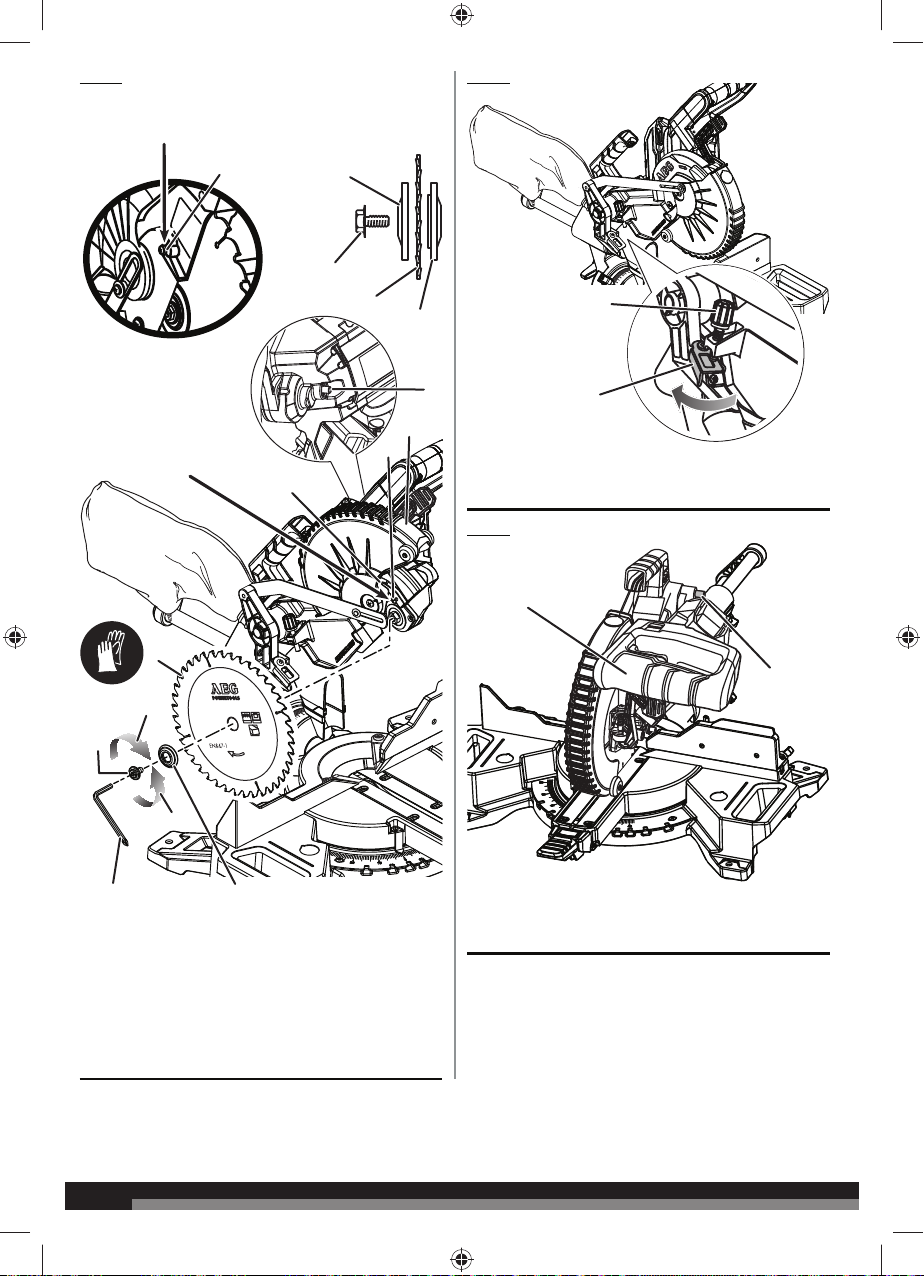
The following tools (not included) are needed for making adjustments:
1
7
8
9
10
11
13
12
14
15
16
1718
19
20
21
22
31
24
25
26
28 29
27
COMBINATION SQUARECOMBINATION WRENCHFRAMING SQUARE HEX KEY
3MM
1 - “D” Handle
2 - Head lock pin
3 - Blade wrench storage
4 - Single/dual bevel selector
5 - Bevel lock knob
6 - Sliding fence adjustment knob
7 - Switch trigger
8 - Lower guard lock out lever
9 - Upper blade guard
10 - Lower blade guard
11 - Sliding fence
12 - Work clamp
13 - Lift handle
14 - “No hands zone” boundary line
15 - “No hands zone” label
16 - Mitre detent release button
17 - Mitre lock lever
18 - Control arm
19 - Throat plates
20 - Mitre scale/ Mitre scale detent plate
21 - Turning table
22 - Saw base
23 - Bevel stop turret
24 - Fixed fence
25 - Depth stop
26 - Slide bar
27 - Dust bag
28 - Carrying handle
29 - Depth control knob
30 - LED light button
31 - Fence extension
32 - Spindle lock button
33 - Saw blade
34 - Mounting holes
35 - Bevel scale
36 - Screws for adjusting mitre angle
37 - Bevel stop adjustment screw
38 - Sliding lock knob
30
32
2
645
23
3
23
34
36
34
13
34
35
37
33
Ø 184 mm
n
max.
7900
Ø 20 mm
40HW 1.6mm
38

4
4
1- Mounting holes
2 - Mounting surface
3 - Base
6
1
2
3
5
4
2
11
3
2
1
3
1
3
2
2
1
Fig. 3Fig. 1
1 - Sliding fence
2 - Slot
3 - Sliding fence adjustment knob
1 - Work clamp
2 - Base
3 - Bevel stop turret
Fig. 2
1 - Carrying handle
2 - Blade wrench storage
3 - Blade wrench
4 - Nuts
5 - Screws
6 - “D”handle
Fig. 4
Fig. 5
1 - Exhaust port
2 - Dust bag
4 - Single/dual bevel selector
5 - Work clamp knob
4
3
5

55
Fig. 8Fig. 6
1 - Mitre indicator screw
2 - Mitre scale indicator
3 - Mitre detent release button
4 - Mitre lock lever
5 - Mitre scale / Mitre scale detent plate
1 - Sliding fence
2 - Mitre detent release button
3 - Mitre lock lever
4 - Turning table
5 - Framing square
6 - Fixed fence
7 - Saw blade
8 - Screws
Fig. 7
1 - Indicator screw
2 - Scale indicator
3 - Bevel scale
1
2
3
4
5
0
15
30
22.5
045
30
33.9
15
22.5 33.9 22.5
30 15 0
1
3
2
1
4
6
7
2
3
5
8
0
15
30
22.5

6
6
Fig. 9
1- Mitre detent release button (press to disengage)
2 - Unlocked
3 - Framing square
1 - Sliding fence
2 - Turning table
4 - Saw blade
View of blade not square with fence, adjustments are
required.
1- Mitre scale indicator
2 - Mitre scale/ Mitre scale detent plate
Fig. 10
Fig. 12
2 - Framing square
3 - Turning table
4 - Fixed fence
1 - Saw blade
3
1
Fig. 11
11
3
4
2
2
4
1
2
0
15
30
22.5
Press the mitre detent release button to rotate the turning
table.
2

77
1 - Saw blade
2 - Mitre lock lever
3 - Turning table
4 - Combination square
Correct view of blade square with turning table
Fig. 14
Fig. 15
1
2
3
4
Fig. 13
0
15
30
22.5
2
1
2
1
1 -
Combination square2 -
Saw blade
View of blade not square with turning table, adjustments are
required.

8
8
Note: Before use, replace blade bolt cover screw and
tighten securely to prevent guard movement.
Note: Before use, replace
blade bolt cover screw and
tighten securely to prevent
guard movement
12
3
4
5
6
1
8
29
3
4
To loosen
To tighten
Fig. 16
0
15
30
22.5
1- Blade bolt cover screw
2 - Outer flange
3 - Blade bolt
4 - Saw blade
5 - Inner flange
6 - Blade bolt cover
7 - Spindle lock button
8 - Lower blade guard
9 - Blade wrench
Fig. 17
Fig. 18
1- Depth control knob
2 - Depth stop
1- “D” handle
2 - Head lock pin
0
15
30
22.5
1
1
2
2
7
Ø 184 mm
n
max.
7900
Ø 20 mm
40HW 1.6mm

99
Fig. 19
Fig. 20
1- LED button
Fig. 21
Fig. 22
1 - Push back
Cross cut
1 - Work clamp
2 - Mitre detent release button
3 - Mitre lock lever
1
1
1
2
2
3
Shadow of
blade teeth
projected
onto workpiece
0
15
30
22.5
0
30
22.5
0
15
30
22.5
0
15
30
22.5
2
1
3
1 - Slide cut
2 - Slide saw arm forward, pull lower guard lock out lever
to unlock lower guard, then push down.
3 - Sliding lock knob

10
10
Fig. 23
Fig. 24
Mitre cut
1 - Work clamp
Mitre cut
1 - Bevel lock knob
2 - Single/dual bevel selector
3 - Bevel stop adjustment screw
1
1
Bevel cut
1 - Work clamp
Fig. 25
Fig. 26
4
1
030
15
22.5 33.9
33.9º
45º 48º
015
22.5
1
2
3
Compound mitre cut
1 - C-clamp (not included)
4 - Bevel stop turret

11 11
Fig. 27
Fig. 28
1 - Long workpiece
2 - Workpiece supports
2
1
1
Fig. 30
Fig. 29
1 - Wide board
1
23
0
15
30
22.5
0
15
30
22.5
Ceiling
Wall
38°
52°
2
Top edge against fence:
Left side, inside corner
Right side, outside corner
1
Ceiling
Wall
45°
45°
1
4
3
Top edge against fence:
Left side, inside corner
Right side, outside corner
2
1 - Cut these grooves with saw
2 - Use a chisel to cut out the middle
3 - Workpiece
1 - Inside corner
2 - Mitre fence
3 - Outside corner
4 - Turning table
1 - Mitre fence
2 - Turning table

12
12
030
15
22.5 33.9
015 22.5
Fig. 31
Fig. 32
Fig. 35
Right
2
1
1
3
Fig. 34
Wrong
Fig. 33
1 - Spring clamp (not included)
2 - Molding
3 - Sliding fence
Fig. 36
1 - Bevel stop adjustment screw
2
3
1Bottom edge against fence:
Left side, inside corner
Right side, outside corner
12
1 - Hex key
2 - 0° Bevel top screw
015
22.5
030
15
22.5 33.9
1 - Fixed fence
2 - Spring clamp (not included)
3 - Turning table
Crown molding nested against front facing mitre fence

13 13
Fig. 37
1 - Throat plates
2 - Tensioning nut
3 - Lock nut
1 - Throat plates
2 - Mitre lock lever
2
Unlock
Lock
1
Fig. 38
1
3
2

14
14
TECHNICAL DATA DUAL BEVEL SLIDER MITRE SAW PSD18B-184X
Voltage 18 V
Max. cutting depth 68 mm
No-load speed 3700 min-1
Saw blade diameter x hole diameter 184 mm×20 mm
Saw blade thickness / kerf 1.0 mm / 1.6 mm
Max. cutting capacity
Mitre 0°/ Bevel 0° 38.1 mm × 184.2 mm
Mitre 0°/ Bevel 45° (R) 19.1 mm × 184.2 mm
Mitre 0°/ Bevel 45° (L) 38.1 mm × 184.2 mm
Mitre 45°/ Bevel 0° 38.1 mm × 139.7 mm
Mitre 45°/ Bevel 45° (R) 19.1 mm × 139.7 mm
Mitre 45°/ Bevel 45° (L) 38.1 mm × 139.7 mm
Vertical Base
Mitre 45°/ Bevel 0° 19.1 mm × 88.9 mm
Nested Crown
Mitre 45°/ Bevel 0° 88.9 mm
Min. workpiece dimensions 130 mm × 35 mm × 2.5 mm
REPLACEMENT PARTS
Saw blade 089294001085
Combination wrench 089294001078
Work clamp 089294001800
Dust bag 089294001705
BATTERY AND CHARGER
Compatible battery pack
(not included)
Compatible charger
(not included)
L1815R
L1820R
L1825R
L1830R
L1840R
L1850R
L1860R
BL1218
AL1218G
Use AEG 18V battery and charger only.
WARNING!
Read all safety warnings and all instructions. Failure to follow
WKHZDUQLQJVDQGLQVWUXFWLRQVPD\UHVXOWLQHOHFWULFVKRFN¿UHDQG
or serious injury.
Save all warnings and instructions for future reference.
GENERAL SAFETY WARNINGS
WARNING
When using electric tools, basic safety precautions should
DOZD\VEHIROORZHGWRUHGXFHWKHULVNRI¿UHHOHFWULFVKRFNDQG
personal injury. Read all these instructions before attempting to
operate this product and save these instructions.
Keep work area clear. Cluttered areas and benches invite injuries.
Consider work area environment. Do not expose tools to rain. Do
not use tools in damp or wet locations. Keep work area well lit. Do
QRWXVHWRROVLQWKHSUHVHQFHRIÀDPPDEOHOLTXLGVRUJDVHV
Guard against electric shock. Avoid body contact with earthed
or grounded surfaces (e.g. pipes, radiators, ranges, refrigerators).
Keep other persons away. Do not let persons, especially children,
be involved in the work, touch the tool or the extension cord, and
keep them away from the work area.
Store idle tools. When not in use, tools should be stored in a dry
locked-up place, out of reach of children.
Do not force the tool. It will do the job better and safer at the rate
for which it was intended.
Use the right tool. Do not force small tools to do the job of a heavy
duty tool. Do not use tools for purposes not intended, for example,
do not use circular saws to cut tree limbs or logs.
Dress properly. Do not wear loose clothing or jewellery, they can
be caught in moving parts. Non-skid footwear is recommended
when working outdoors. Wear protective hair covering to contain
long hair.

15 15
Use protective equipment. Use safety glasses. Use face or dust
mask if working operations create dust.
Connect dust extraction equipment. If the tool is provided for
WKHFRQQHFWLRQRIGXVWH[WUDFWLRQDQGFROOHFWLQJHTXLSPHQWHQVXUH
these are connected and properly used.
Do not abuse the cord. Never yank the cord to disconnect it from
the socket. Keep the cord away from heat, oil and sharp edges.
Secure work. Where possible, use clamps or a vice to hold the
work. It is safer than using your hand.
Do not overreach. Keep proper footing and balance at all times.
Maintain tools with care. Keep cutting tools sharp and clean for
better and safer performance. Follow instruction for lubricating
and changing accessories. Inspect tool cords periodically and if
damaged, have them repaired by an authorised service facility.
Inspect extension cords periodically and replace if damaged. Keep
handles dry, clean and free from oil and grease.
Disconnect tools. When not in use, before servicing and when
changing accessories such as blades, bits and cutters, disconnect
tools from the power supply.
Remove adjusting keys and wrenches. Form the habit of
checking to see that keys and adjusting wrenches are removed
from the tool before turning it on.
Avoid unintentional starting. Ensure switch is in “off” position
when installing battery pack.
Use outdoor extension leads. When the tool is used outdoors,
use only extension cords intended for outdoor use and so marked.
Stay alert. Watch what you are doing, use common sense and do
not operate the tool when you are tired.
Check damaged parts. Before further use of tool, it should be
carefully checked to determine that it will operate properly and
perform its intended function. Check for alignment of moving parts,
binding of moving parts, breakage of parts, mounting and any other
conditions that may affect its operation. A guard or other part that is
damaged should be properly repaired or replaced by an authorised
service centre unless otherwise indicated in this instruction manual.
Have defective switches replaced by an authorised service centre.
Do not use the tool if the switch does not turn it on and off.
Warning. The use of any accessory or attachment other than the
one recommended in this instruction manual may present a risk of
personal injury.
+DYH\RXUWRROUHSDLUHGE\DTXDOL¿HGSHUVRQ This electric tool
complies with the relevant safety rules. Repairs should only be
FDUULHGRXWE\TXDOL¿HGSHUVRQVXVLQJRULJLQDOVSDUHSDUWVRWKHUZLVH
this may result in considerable danger to the user.
MITRE SAW SAFETY WARNINGS
Always clamp the workpiece safely and securely.
(QVXUHWKDWWKHPDFKLQHLVDOZD\VVWDEOHDQGVHFXUHHJ¿[HGWR
a bench).
Always wear ear protectors. Exposure to noise can cause hearing
loss.
Always wear safety goggles when using the machine. It is
recommended to wear gloves for handling blades and rough
material, as well as sturdy non-slip shoes which also protect the
feet from workpieces that may fall from the cutting area.
Always remove the plug or battery pack before carrying out any
adjustment, maintenance or cleaning on the machine.
Ensure the machine is switched off before installing or removing
the battery pack.
Do not stand in a line with the saw blade in front of the machine.
Always stand aside of the saw blade.
.HHSKDQGV¿QJHUVDQGDUPVDZD\IURPWKHURWDWLQJVDZEODGH
Never reach into the area near the blade, unless the blade has
completely stopped.
Before use, thoroughly check the tool for any damage or material
fatigue. Repairs should only be carried out by authorised service
agents.
Always use the guards on the machine. Do not use the machine if
the guards are not in place and working correctly.
Do not clamp the protective swing guard.
If the workpiece or blade becomes jammed, turn the mitre saw
“OFF”. Wait for all moving parts to stop and disconnect the plug
from the power source and/or remove the battery pack. Then work
to free the jammed material.
Never alter of modify the saw or its function. Your safety may be
compromised.
Do not use saw blades which are cracked, damaged, or deformed.
Do not use saw blades made of high-speed steel.
Only use saw blades which are sharp. Replace blunt blades with a
new replacement.
Use a blade holder or wear gloves when handling a saw blade.
Always use blades with the correct size and shape of arbour holes.
Blades that do not match the mounting hardware of the saw will run
eccentrically, causing loss of control.
8VH RQO\ ZRRGZRUNLQJ EODGHV VSHFL¿HG LQ WKLV PDQXDO ZKLFK
comply with EN 847-1.
'RQRWXVHDQ\ÀDQJHVZDVKHUVDQGQXWVWRVHFXUHWKHVDZEODGH
other than those supplied or indicated in the instruction manual.
,W LV HVVHQWLDO WR DGKHUH WR WKH PD[LPXP VSHHG VSHFL¿HG RQ WKH
saw blade.
It is necessary to select a saw blade which is suitable for the
material being cut.
1HYHUXVHWKHPLWUHVDZWRFXWPDWHULDOVRWKHUWKDQWKRVHVSHFL¿HG
in the intended use section in this manual.
Replace the table insert when worn or damaged.
Before work, make a dummy cut without the motor turned on so the
position of the blade, operation of the guards with respect to other
machine parts, and workpiece may be checked.
Refrain from removing any cut-offs or other parts of the workpiece
from the cutting area while the machine is running and the saw head
is not in the rest position.
When transporting the machine, use only transportation devices
and never use guards for handling or transportation.
The handle lock must always be engaged when transporting the
mitre saw.
.HHSWKHÀRRUDUHDIUHHRIORRVHPDWHULDOHJFKLSVDQGFXWRIIV
/RQJZRUNSLHFHVPXVWEHDGHTXDWHO\VXSSRUWHG
6WRFNKDYLQJDURXQGRULUUHJXODUFURVVVHFWLRQVXFKDV¿UHZRRG
which cannot be clamped securely by the provided clamp must
not be cut. When sawing into the edge of thin or layered stock, a
suitable auxiliary fence must be used to provide support.
The dust produced when using this tool may be harmful to health.
Use a dust suction system and wear a suitable dust protection
mask. Remove deposited dust thoroughly, e.g. with a vacuum
cleaner.
Connect the saw to a dust-collecting device when sawing wood.
Do not replace the LED with a different type. Any repairs must only
be carried out by the manufacturer or authorised service agent.
SAFETY INSTRUCTIONS FOR WOOD CUTTING BLADE
Please read the manual and instructions carefully before using the
saw blade and the machine.
The machine must be in good condition, the spindle without
deformation and vibration.
Do not use the saw without the guards in position, keep guards in
good working order and properly maintained.
(QVXUH WKH RSHUDWRU LV DGHTXDWHO\ WUDLQHG LQ VDIHW\ SUHFDXWLRQV
adjustment, and operation of the machine.

16
16
Always wear goggles and ear protection when using the machine. It
is recommended to wear gloves, sturdy non-slip shoes and apron.
Before using any accessory, consult the instruction manual. The
improper use of an accessory can cause damage and increase the
potential for injury.
8VHRQO\EODGHVVSHFL¿HGLQWKLVPDQXDOFRPSO\LQJZLWK(1
Observe the maximum speed marked on the saw blade. Ensure
WKHVSHHGPDUNHGRQWKHVDZEODGHLVDWOHDVWHTXDOWRWKHVSHHG
marked on the saw.
Always use blades with correct size and shape of arbour holes.
Blades that do not match the mounting hardware of the saw will run
eccentrically, causing loss of control.
Do not use blades of larger or smaller diameter other than
UHFRPPHQGHG'RQRWXVHDQ\VSDFHUVWRPDNHWKHEODGH¿WRQWR
the spindle.
Check the tips of the saw blade for damage or abnormal appearance
EHIRUHHDFKXVH7LSVWKDWDUHGDPDJHGRUORRVHFDQEHFRPHÀ\LQJ
objects in use and increase the chance of personal injury.
Do not use cracked or distorted saw blades. Do not use saw blades
that are damaged or deformed.
Scrap the saw blade if damaged, deformed, distorted or cracked,
repairing is not permitted.
Do not use HSS blades.
Ensure the saw blade is mounted correctly, tighten the arbor nut
VHFXUHO\EHIRUHXVHWLJKWHQLQJWRUTXHDSSUR[1P
Fastening screw and nuts shall be tightened using the appropriate
spanner, etc.
Extension of the spanner or tightening using hammer blows is not
permitted.
0DNHVXUHWKHEODGHDQGÀDQJHVDUHFOHDQDQGWKHUHFHVVHGVLGHV
of the collar are against the blade.
Make sure the blade rotates in the correct direction.
Before work, make a dummy cut without the motor turned on so the
position of the blade, operation of the guards with respect to other
machine parts and workpiece may be checked.
Never leave the machine unattended.
Do not apply lubricants on the blade when it is running.
Never perform any cleaning or maintenance work when the machine
is still running and the head is not in the rest position.
Never attempt to stop a machine in motion rapidly by jamming a tool
or other means against the blade, serious accidents can be caused
unintentionally in this way.
Disconnect the saw from the mains supply or remove battery pack
before changing blades or carrying out maintenance.
Pay attention to blade packing and unpacking, it is easy to be
injured by the sharp blade tips.
Use a blade holder or wear gloves when handling a saw blade.
Keep and store the blade in original packaging or other suitable
packaging, keep in dry conditions and away from chemicals which
may damage the blade.
SPECIFIED CONDITIONS OF USE
The dual bevel slider mitre saw is intended for sawing solid and
bonded wood with or without glued veneer, plastics, and materials
similar to wood.
The dual bevel slider mitre saw is intended to be used only by adult
operators who have read the instruction manual and understand the
risks and hazards.
7KHGXDOEHYHOVOLGHUPLWUHVDZLVGHVLJQHGWREH¿[HGDWWKHEDVH
WR D VROLG EHQFK WRS ,I WKH EDVH LV QRW VHFXUHO\ ¿[HG WKH ZKROH
machine may move during cutting operations, which increases the
possibility of serious personal injury.
The dual bevel slider mitre saw is designed make bevel and mitre
cuts. The capacities for the various cuts are provided in the product
VSHFL¿FDWLRQVLQWKLVPDQXDO
The dual bevel slider mitre saw is to be used in dry conditions, with
H[FHOOHQWDPELHQWOLJKWLQJDQGDGHTXDWHYHQWLODWLRQ
The dual bevel slider mitre saw is intended for consumer use and
should only be used as described above and is not intended for any
other purpose.
RESIDUAL RISKS
Even when the dual bevel slider mitre saw is used as prescribed,
it is still impossible to completely eliminate certain residual risk
factors. The following hazards may arise and the operator should
pay special attention to avoid the following:
ŶRisk of contact with uncovered parts of the rotating saw blade.
ŶKick-back of work pieces or parts of work pieces due to improper
adjustment or handling.
ŶCatapulting of faulty carbide tips from the saw blade. Wear Eye
protection at all times.
ŶDamage to the respiratory system. Wear respiratory protection
masks containing filters appropriate to the materials being
ZRUNHG (QVXUH DGHTXDWH ZRUNSODFH YHQWLODWLRQ 'R QRW HDW
drink or smoke in the work area.
ŶDamage to hearing if effective hearing protection is not worn.
WARNING
Dust from certain paints, coatings, and materials may cause
irritation or allergic reactions. Dust from wood such as oak,
beech, MDF, and others are carcinogenic. Materials containing
DVEHVWRV VKRXOG RQO\ EH ZRUNHG RQ RU SURFHVVHG E\ TXDOL¿HG
specialist operators.
WARNING
Injuries may be caused or aggravated by prolonged use of a
tool. When using any tool for prolonged periods, ensure you take
regular breaks.
ASSEMBLY
UNPACKING
Packing list
ŶDust bag x 1
ŶWork clamp x 1
ŶSliding fence x 1
ŶCarrying handle x 1
ŶNylon nut x 2
ŶHex socket bolt x 2
ŶOperation manual x 1
7KHSURGXFWUHTXLUHVDVVHPEO\
Carefully lift saw from the carton by the carrying handle and the saw
base, and place it on a level work surface.
The product has been shipped with the saw arm secured in the
down position. To release the saw arm, push down on the top of the
saw arm, cut the tie-wrap, and pull out the head lock pin.
WARNING
The saw arm is spring loaded. Hold the handle down to prevent
saw arm from snapping up when cutting the tie-wrap. Failure to
do so could result in possible serious injury.
ŶLift the saw arm by the handle. Hand pressure should remain on

17 17
the saw arm to prevent sudden rise upon release of the tie wrap.
ŶInspect the product carefully to make sure no breakage or
damage occurred during shipping.
ŶDo not discard the packing material until you have carefully
inspected and satisfactorily operated the product.
ŶThe product is factory set for accurate cutting. After assembling
it, check for accuracy. If shipping has influenced the settings,
refer to specific procedures explained in the manual.
WARNING
If any parts are damaged or missing, do not operate the product
until the parts are replaced. Use of the product with damaged or
missing parts could result in serious personal injury.
WARNING
Do not attempt to modify the product or create accessories not
recommended for use with the product. Any such alteration or
PRGL¿FDWLRQLVPLVXVHDQGFRXOGUHVXOWLQDKD]DUGRXVFRQGLWLRQ
leading to possible serious personal injury.
WARNING
To prevent accidental starting that could cause serious personal
injury, always remove the battery pack from the product when
assembling parts.
MOUNTING HOLES
6HH¿JXUH
WARNING
Before starting any cutting operation, mount the product to a
VROLG ZRUNEHQFK 1HYHU RSHUDWH WKH SURGXFW RQ WKH ÀRRU RU LQ
a crouched position. Failure to heed this warning can result in
serious personal injury.
7KHSURGXFWVKRXOGEHPRXQWHGWRD¿UPVXSSRUWLQJVXUIDFHVXFK
as a workbench, mounting board. Four bolt holes have been
provided in the saw base for this purpose. Each of the four mounting
holes should be bolted securely using 7.9 mm (5/16 in.) machine
bolts, lock washers, and hex nuts (not included). Bolts should be
RI VXI¿FLHQW OHQJWK WR DFFRPPRGDWH WKH VDZ EDVH ORFN ZDVKHUV
hex nuts, and the thickness of the workbench. Tighten all four bolts
securely.
7KHKROHSDWWHUQIRUPRXQWLQJWRDZRUNEHQFKLVVKRZQLQ¿JXUH
Carefully check the workbench after mounting to make sure that no
movement can occur during use. If any tipping, sliding, or walking is
QRWHGVHFXUHWKHZRUNEHQFKWRWKHÀRRUEHIRUHRSHUDWLQJ
INSTALLING CARRYING HANDLE
6HH¿JXUH
ŶRemove the screws and nuts from the carrying handle and set
aside.
ŶSlide the carrying handle onto the saw arm, aligning the holes
on the arm with the holes in the handle.
ŶInsert the screws and nuts into the holes and tighten securely.
WARNING
Only use the lift handles on the table and/or the carrying handle
on top to move or carry the product. Never use the “D” handle and
always remove the battery before moving. Carrying the product
with the “D” handle may cause inadvertent switch actuation and
may result in serious personal injury.
BLADE WRENCH
6HH¿JXUH
A blade wrench is packed with the product. One end of the wrench
is a Phillips screwdriver and the other end is a hex key. Use the
hex key end when installing or removing blade and the Phillips end
when removing or loosening screws. A storage area for the blade
wrench is located in the carrying handle on the top of the product.
INSTALLING SLIDING FENCE
6HH¿JXUH
ŶTurn the sliding fence adjustment knob counterclockwise, to
clear fence slots.
ŶInstall the sliding fence. Lower fence into fence slot. Be sure
side of fence lines up flush with side of fixed fence.
ŶTighten sliding fence adjustment knob securely.
NOTE: To remove the sliding fence, loosen the sliding fence
adjustment knob. Then, slide the fence towards the blade to take
out.
INSTALLING THE WORK CLAMP
6HH¿JXUH
WARNING
In some operations, the work clamp assembly may interfere with
the operation of the blade guard assembly. Always make sure
there is no interference with the blade guard prior to beginning
any cutting operation to reduce the risk of serious personal injury.
The work clamp provides greater control by clamping the workpiece
to the table. It also prevents the workpiece from creeping towards
the saw blade.
Depending on the cutting operation and the size of the workpiece,
it may be necessary to use a C-clamp (not included) instead of the
work clamp to secure the workpiece prior to making the cut.
To install the work clamp:
ŶPlace the shaft of the work clamp in either hole on the turning
table base.
ŶRotate the work clamp knob on the work clamp to move it in or
out as needed.
NOTE: Many of the illustrations in this manual show only portions
of the product. This is intentional so that we can clearly show points
being made in the illustrations. Never operate the product without all
guards securely in place and in good operating condition.
DUST BAG
6HH¿JXUH
ŶTo install the dust bag and frame assembly, slide the open end
of the frame onto the exhaust port.
ŶFor efficient operation, empty the dust bag before it is half full.
This will permit better air flow through the bag.

18
18
SQUARING THE SAW BLADE TO THE FENCE
6HH¿JXUHV
ŶRemove the battery pack from the product.
ŶPull the saw arm all the way down and lock in transport position.
ŶLift the mitre lock lever to unlock the turning table.
ŶPress the mitre detent release button and rotate the turning
table until the pointer on the mitre scale is positioned at 0°.
ŶRelease the mitre detent release button and allow the turning
table to engage the 0° detent position.
ŶPush the mitre lock lever down to lock the turning table.
ŶLoosen the bevel lock knob and set the product at the 0° bevel
angle.
ŶSecurely tighten the bevel lock knob.
Ŷ /D\ D IUDPLQJ VTXDUH IODW RQ WKH WXUQLQJ WDEOH 3ODFH RQH OHJ
RIWKHVTXDUHDJDLQVWWKHIL[HGIHQFH6OLGHWKHRWKHUOHJRIWKH
VTXDUHDJDLQVWWKHIODWSDUWRIWKHVDZEODGH
NOTE:0DNHVXUHWKDWWKHVTXDUHFRQWDFWVWKHIODWSDUWRIWKH
saw blade, not the blade teeth.
Ŷ 7KHHGJHRIWKHVTXDUHDQGWKHVDZEODGHVKRXOGEHSDUDOOHO
See figure 8.
ŶIf the front or back edge of the saw blade angles away from the
VTXDUHDGMXVWPHQWVDUHQHHGHG6HHILJXUHVDQG
ŶLift the mitre lock lever to unlock the turning table.
ŶPress the mitre detent release button and rotate the turning
table until the pointer is at the left 30° position on the mitre scale
detent plate. See figure 8.
ŶLoosen the 3 screws that hold the mitre scale detent plate in
place.
ŶPress the mitre detent release button and rotate the turning
table to the 0° position on the mitre scale or until the detent
engages in the detent plate.
ŶAdjust the mitre angle until the blade is parallel with the framing
VTXDUHIf adjustments are needed, refer to To adjust the mitre
angle in the Adjustments section.
ŶPush the mitre lock lever down to lock the turning table.
ŶTighten the 2 visible screws that secure the mitre scale detent
plate.
ŶLift the mitre lock lever to unlock the turning table.
ŶPress the mitre detent release button and rotate the turning
table to the left 30° position on the mitre scale. See figure 8.
ŶTighten the remaining screw to secure the mitre scale detent
plate.
SQUARING THE BLADE TO THE TURNING TABLE
6HH¿JXUHV
To square the blade at 0°:
ŶRemove the battery pack from the product.
ŶPull the saw arm all the way down and engage the head lock pin
to hold the saw arm in transport position.
ŶLift the mitre lock lever, then depress and hold the mitre detent
release button to release the turning table.
ŶRotate the turning table until the scale indicator is positioned
at 0°.
ŶRelease the mitre detent release button and allow the turning
table to engage the 0° detent position. Push the mitre lock lever
down to secure the turning table.
ŶPush the single/ dual bevel selector inward. See figure 4.
ŶLoosen bevel lock knob and tilt saw arm until it is seated in the
positive 0° bevel stop (blade set 90° to turning table). Tighten
bevel lock knob.
Ŷ 3ODFHDFRPELQDWLRQVTXDUH DJDLQVW WKHWXUQLQJWDEOHDQG WKH
flat part of saw blade.
NOTE:0DNHVXUHWKDWWKHVTXDUHFRQWDFWVWKHIODWSDUWRIWKH
saw blade, not the blade teeth.
ŶRotate the blade by hand and check the blade-to-table
alignment at several points.
Ŷ 7KHHGJHRIWKHVTXDUHDQGWKHVDZEODGHVKRXOGEHSDUDOOHODV
shown in figure 13.
ŶIf the top or bottom of the saw blade angles away from the
VTXDUHDVVKRZQLQILJXUHDGMXVWPHQWVDUHQHHGHG
ŶLoosen the bevel lock knob.
ŶAdjust 0° bevel stop screw to bring saw blade into alignment
ZLWKWKHVTXDUH6HH %HYHO$GMXVWPHQWLQWKH $GMXVWPHQWV
section.
ŶRetighten bevel lock knob. Recheck blade-to-table alignment.
To square the blade at 45°:
ŶLoosen the bevel lock knob and set the saw arm at 45° bevel.
Tighten bevel lock knob.
NOTE: To obtain right bevel angles, pull the single/ dual bevel
selector out and tilt the saw to the desired angle.
Ŷ 8VLQJDFRPELQDWLRQVTXDUHFKHFNWKHEODGHWRWDEOHDOLJQPHQW
as described earlier.
ŶIf adjustments are needed, refer to 45° Bevel Adjustment in the
Adjustments section.
Ŷ 7KH SURGXFW KDV VHYHUDO VFDOH LQGLFDWRUV $IWHU VTXDULQJ
adjustments have been made, it may be necessary to loosen
the indicator screws and reset them to zero. See figures 6-7.
OPERATION
WARNING
Do not allow familiarity with products to make you careless.
5HPHPEHU WKDW D FDUHOHVV IUDFWLRQ RI D VHFRQG LV VXI¿FLHQW WR
LQÀLFWVHYHUHLQMXU\
WARNING
Always wear eye protection with side shields. Failure to do so
could result in objects being thrown into your eyes, resulting in
possible serious injury.
WARNING
Do not use any attachments or accessories not recommended
by the manufacturer of the product. The use of attachments or
accessories not recommended can result in serious personal
injury.
WARNING
To avoid serious personal injury, always push the mitre lock lever
down and tighten the bevel lock knob securely before making a
cut. Failure to do so could result in movement of the control arm
or turning table while making a cut.
WARNING
Do not start the product without checking for interference
between the blade and the mitre fence. Damage could result
to the blade if it strikes the mitre fence during operation of the
product. Failure to heed this warning can also result in serious
personal injury.

19 19
INSTALLING/REMOVING THE BATTERY PACK
6HH¿JXUH
ŶPlace the battery pack in the product. Align the raised rib on
the battery pack with the groove inside the saw, then slide the
battery pack into the product.
ŶMake sure the latches on each side of the battery pack snap
into place and the battery pack is secured in the saw before
beginning operation.
ŶDepress the latches to remove the battery pack.
ŶFor complete charging instructions, see the operator’s manuals
for your battery pack and charger.
WARNING
Always remove battery pack from the product when you are
assembling parts, making adjustments, cleaning, or when not in
use. Removing battery pack will prevent accidental starting that
could cause serious personal injury.
REPLACING THE BLADE
6HH¿JXUH
WARNING
%HIRUHUHPRYLQJDQG¿WWLQJWKHEODGHPDNHVXUHWRZHDUVDIHW\
gloves.
WARNING
A 184 mm (7-1/4 in.) blade is the maximum blade capacity of the
SURGXFW1HYHUXVHDEODGHWKDWLVWRRWKLFNWRDOORZRXWHUÀDQJH
WRHQJDJHZLWKWKHÀDWVRQWKHVSLQGOH/DUJHUEODGHVZLOOFRPH
in contact with the blade guards, while thicker blades will prevent
the blade bolt from securing the blade on the spindle. Either of
these situations could result in a serious accident and can cause
serious personal injury.
WARNING
2QO\XVH WKHEODGHVSHFL¿HGLQWKLVPDQXDODQGLWVVSHHGLVDW
OHDVWHTXDOWRWKHVSHHGPDUNHGRQWKHSURGXFW
ŶRemove the battery pack from the product.
ŶRaise saw arm.
ŶRotate lower blade guard up and loosen blade bolt cover screw.
Slide blade bolt cover towards upper blade guard to expose the
blade bolt.
ŶDepress the spindle lock button and rotate the blade bolt until
the spindle locks.
ŶUsing the blade wrench provided, loosen and remove the blade
bolt.
NOTE: The blade bolt has left hand threads. Turn blade bolt
clockwise to loosen.
ŶRemove the outer flange. Wear gloves. Remove the blade.
Wear gloves when handling the saw blade.
ŶWipe a drop of oil onto the inner flange and the outer flange
where they contact the blade.
WARNING
,ILQQHUÀDQJHKDVEHHQUHPRYHGUHSODFHLWEHIRUHSODFLQJEODGH
on spindle. Failure to do so could cause an accident since blade
will not tighten properly.
ŶWear gloves. Fit saw blade inside upper blade guard and onto
spindle. The blade teeth point downward at the front of saw as
shown in figure 16.
ŶReplace the outer flange. The double “D” flats on the blade
washers align with the flats on the spindle.
ŶDepress spindle lock button and replace blade bolt.
NOTE: The blade bolt has left hand threads. Turn blade bolt
counterclockwise to tighten.
WARNING
Always install the blade with the blade teeth and the arrow
printed on the side of the blade pointing down at the front of
the saw. The direction of blade rotation is also stamped with an
arrow on the upper blade guard.
ŶTighten blade bolt securely.
ŶReplace blade bolt cover and tighten blade bolt cover screw
securely.
ŶLower the blade guard.
ŶRaise and lower the saw arm to ensure lower blade guard
functions correctly.
USING THE DEPTH GUIDE
6HH¿JXUH
When used, the depth guide limits the downward travel of the blade
when cutting dadoes and other non-through cuts.
To use the depth guide:
ŶRemove the battery pack from the product.
ŶRotate the depth stop outward.
ŶWith the depth control knob touching the depth stop, adjust the
depth control knob by turning the knob until the desired depth
of cut is attained.
ŶRotate the depth stop inward for normal through cuts.
NOTE: The depth stop must be pushed in before locking/
unlocking the saw arm.
LOCKING / UNLOCKING THE SAW ARM
6HH¿JXUH
When locking and unlocking the saw arm, it is not necessary to
loosen the depth control knob, however the depth stop must be
pushed in.
To unlock and raise the saw arm:
ŶFirmly grasp the “D” handle and apply downward pressure while
at the same time pulling the head lock pin out and away from
the saw housing.
ŶRaise the saw arm.
To lock the saw arm:
ŶPull the lower guard lock out lever to right side to unlock the
lower guard.
ŶFirmly grasp the “D” handle and apply downward pressure until
head stops. Push in the head lock pin towards the saw allowing
it to lock the saw into place.
CUTTING WITH THE PRODUCT
WARNING
Secure the workpiece to the mitre saw base. Use the clamp
provided and, where necessary, use additional clamps or
holding mechanisms to prevent unintentional movement of the
workpiece while cutting.

20
20
WARNING
Never move the workpiece or make adjustment to any cutting
angle while the saw is running and the blade is rotating. Any
slip can result in contact with the blade causing serious personal
injury.
WARNING
Do not try to cut narrow pieces using the sliding feature. Failure
to heed this warning could result in serious personal injury.
LED LIGHTING SYSTEM
6HH¿JXUH
The LED lighting system casts the shadow of the blade onto the
ZRUNSLHFH7KLVUHVXOWVLQJUHDWHUDFFXUDF\RIFXWVDQGUHTXLUHVQR
adjustments.
ŶTo use this feature, press the LED button. The LED light will
automatically turn off after 15 seconds.
NOTE: The LED light will automatically turn on when the switch
trigger is depressed.
ŶBring the saw arm down so that the blade is approximately 6.3
mm (1/4 in.) from the workpiece. The shadow of the blade will
be projected onto the workpiece, indicating where the blade
teeth will make contact as the cut is made.
TO SLIDE CUT
6HH¿JXUHV
WARNING
Never make a cut by pulling the saw towards you as the blade
can climb on top of the workpiece and come towards you. Failure
to heed this warning could result in serious personal injury.
ŶThe sliding feature will cut workpieces up to 184 mm (7-1/4 in.)
wide x 38 mm (1-1/2 in.) thick.
Ŷ :LWKWKHVDZRIISXOOWKHVDZDUPIRUZDUG6TXHH]HWKHVZLWFK
trigger (let blade reach maximum speed), then push the blade
down on top of the workpiece then back towards the rear of the
saw to make a cut. Cuts are made by: pushing the saw blade
away from you and towards the bevel scale at the back of the
saw, stopping when the full rear position has been reached after
each cut. When the saw is running (turned on), never pull the
saw blade towards you or towards the front of the saw.
ŶRaise saw arm to its full height.
ŶPush the mitre lock lever down to secure the turning table.
ŶPlace the workpiece flat on the turning table securely against
the fence. If the board is warped, place the convex side against
the fence. If the concave edge of a board is placed against the
fence, the board could collapse on the blade at the end of the
cut, jamming the blade. See figures 33 - 34.
ŶWhen cutting long pieces of lumber or molding, support the
opposite end of the stock with a roller stand or with a work
surface level with the saw table. See figure 27.
ŶAlign the cutting line on the workpiece with the edge of saw
blade.
ŶLoosen the sliding lock knob by turning the knob
counterclockwise.
ŶPress the LED button to project the blade’s shadow onto the
workpiece.
ŶGrasp the stock firmly with one hand and secure it against
the fence. Use the work clamp or a C-clamp (not included) to
secure the workpiece when possible.
ŶBefore turning on the saw, perform a dry run of the cutting
operation to make sure that no problems will occur when the
cut is made.
ŶWith the saw off, grasp the saw handle firmly then pull the saw
forward until the blade arbor (centre of the saw blade) is over
the front of the workpiece.
Ŷ 6TXHH]HWKHVZLWFKWULJJHU DQG DOORZVHYHUDOVHFRQGVIRUWKH
blade to reach maximum speed.
ŶPull the lower guard lock out lever to right side to unlock the
lower guard.
ŶSlowly lower the blade into and through the front edge of the
workpiece.
ŶPush the saw handle away from you and towards the bevel
scale at the back of the saw.
ŶRelease the switch trigger and allow the saw blade to stop
rotating before raising the blade out of workpiece and removing
the workpiece from turning table.
TO MAKE NON-SLIDING CUTS
WARNING
Securely tighten the sliding lock knob when making any non-
sliding cuts. Failure to tighten the knob could result in the saw
head moving during the cutting operation.
TO MITRE CUT / CROSS CUT
6HH¿JXUHV
A cross cut is made by cutting across the grain of the workpiece.
A straight cross cut is made with the turning table set at the 0°
position. Mitre cross cuts are made with the turning table set at
some angle other than zero.
ŶSlide the saw head to its most rearward position and tighten the
sliding lock knob securely.
ŶPull out the head lock pin and lift saw arm to its full height.
ŶLift the mitre lock lever, then depress and hold the mitre detent
release button to release the turning table.
ŶRotate the control arm until the scale indicator aligns with the
desired angle on the mitre scale.
ŶRelease the mitre detent release button, then push the mitre
lock lever down to secure the turning table.
NOTE: <RXFDQTXLFNO\ORFDWHDQG
left or right by releasing the mitre detent release button as you
rotate the control arm. The control arm will seat itself in one
of the positive stop notches, located in the turning table base.
ŶPlace the workpiece flat on the turning table securely against
the fence. If the board is warped, place the convex side against
the fence. If the concave edge of a board is placed against the
fence, the board could collapse on the blade at the end of the
cut, jamming the blade. See figures 33 - 34.
ŶWhen cutting long pieces of lumber or molding, support the
opposite end of the stock with a roller stand or with a work
surface level with the saw table. See figure 27.
ŶAlign cutting line on the workpiece with the edge of saw blade
or LED shadow.
ŶSecure the stock against the fence firmly. Use the work clamp
or a C-clamp (not included) to secure the workpiece when
possible.
ŶBefore turning on the saw, perform a dry run of the cutting
operation to make sure that no problems will occur when the
cut is made.
Ŷ *UDVSWKHVDZKDQGOHILUPO\6TXHH]HWKHVZLWFKWULJJHU$OORZ
several seconds for the blade to reach maximum speed.
ŶPull the lower guard lock out lever to right side to unlock the
This manual suits for next models
2
Table of contents
Other AEG Power Tools manuals