Valley ICON LINK User manual

1
2016-2018 ICON LINK
Valley ICON Panels
Intro 1 –Page 2 –Introduction
Section 1 –Page 3 –Unit Mounting
Section 2 –Pages 4-9 –Unit Wiring
Section 3 –Page 10 –Valley ICON Panel Configuration
Section 4 –Page 11 –ICON LINK Configuration
Section 5 –Page 11 –ICON LINK LED’s
Section 6 –Page 12-13 –Specs and Warranty
2
Introduction
The all new 2016 ICON LINK unit mounts inside the control panel door of Valley ICON
digital irrigation control panels. The ICON LINK unit communicates directly with the
digital control panel to monitor/control the irrigation system remotely via the Wagnet.net
website or Wagnet Mobile App. ICON LINK unit uses a simple serial cable to connect
the unit to the Valley ICON Control panel, plus only has a few simple wire connections
to give the unit power.
This wiring manual includes an overview of the major components of the ICON LINK
unit, and provides detailed wiring instructions of the unit and accessories. See below for
overview, and the following pages for mounting and wiring.
3
ICON LINK Mounting
Turn off the main disconnect on the Valley ICON panel, and open the door fully.
Using the three screws and nuts provided in the install kit, mount the ICON LINK
to the inside of the Valley control panel door as shown below.
4
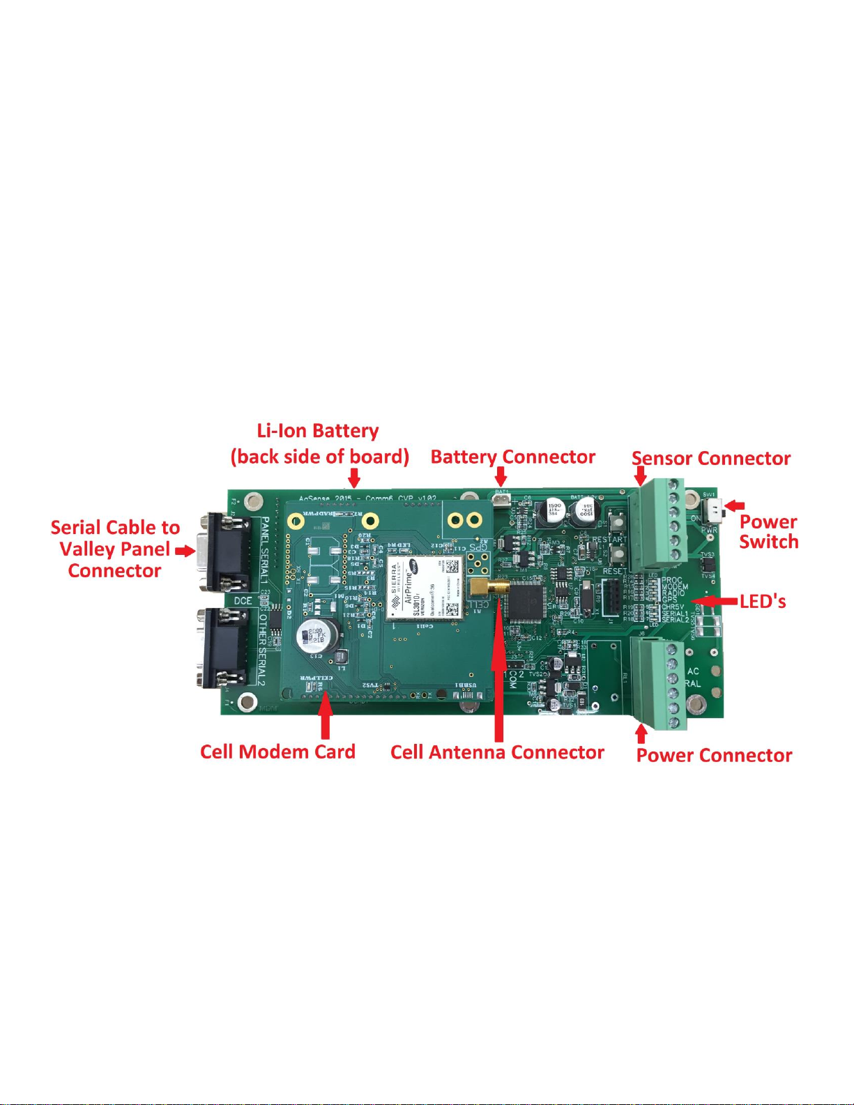
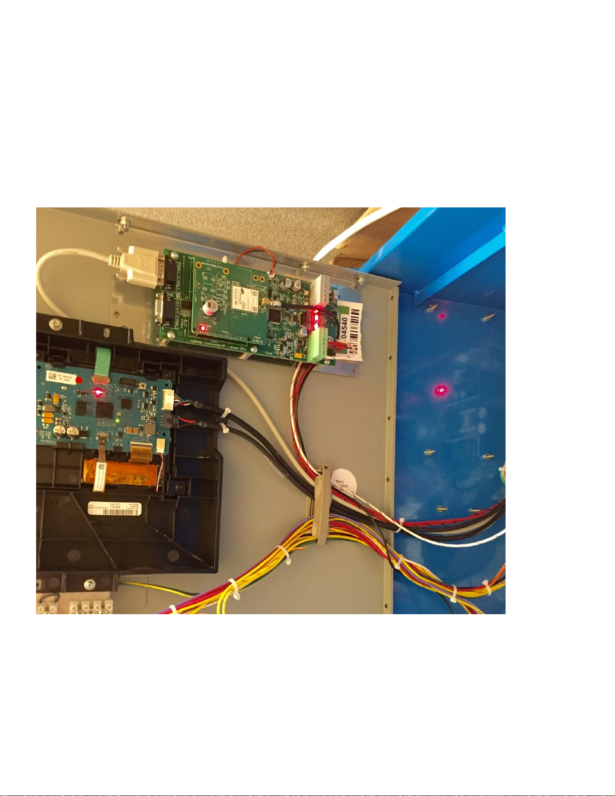
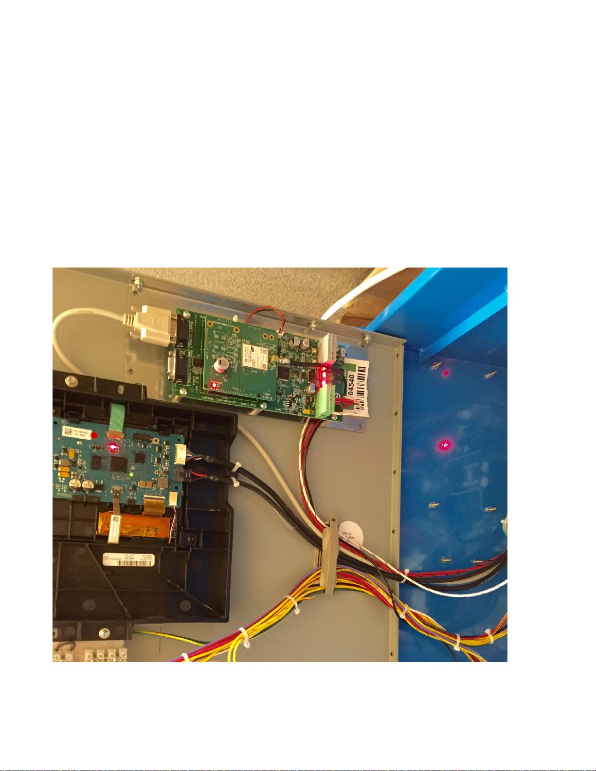
ICON LINK Wiring
ICON LINK Serial Cable Connection
Connect the included Serial Cable to the ICON LINK “Panel Serial 1” port as
shown in the photo below.
5
Connect the opposite end of the Serial Cable to the Valley panel 9 pin Serial
Port (J12) on the SRB Relay board in the panel as shown in the photo below.

6
ICON LINK Power Supply and Wire Connections
1. Attach the magnetic mount cellular antenna onto the top of the
Valley panel and route the antenna wire behind the panel and into
the bottom of the panel using the included cable grip.
2. Then, route the Antenna cable plus the Red, and Red/Black
wires next to the existing door cables/wires and through the
existing wire holders on the Valley panel door up to the ICON
LINK and plug in the wire harness to the ICON LINK as shown in
the photo below.
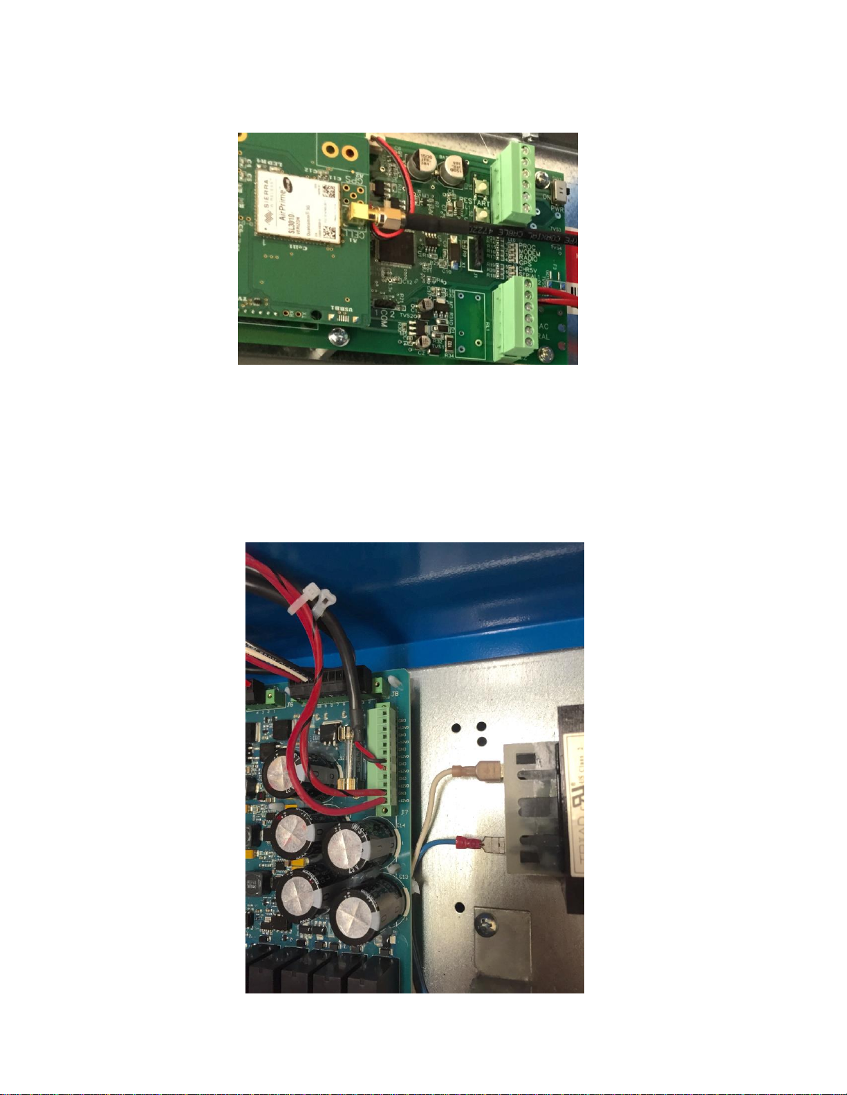
7
3. Then screw the antenna cable end onto the cell modem card as
shown in the photo below (gold screw connection)
4. Use the included zip-ties to secure the wires neatly to the existing
Valley wires as needed.
5. Attach the RED (+12v) and RED/BLACK (GND) wires to the
SRB relay board J7 in the Valley panel as shown below.

8
6. After all wires are attached and secured, make sure the power
switch on the ICON LINK is turned on, and then close the Valley
panel door and turn the main disconnect switch on.
7. If your ICON Link came with the Theft Monitor as a
separate kit, please wire it in as shown above. After wiring in
the Theft Monitor kit, the dealer must call AgSense to enable
the feature. The theft monitor will not work without
completing this step.
8. After completing Step 7, and setting up a phone number/s in the
Alerts config, test the theft monitor feature with the pivot off, by
removing the speed wire from a tower box terminal strip for a
couple minutes, after you receive the alert, you can place the wire
back into the tower box terminal strip.

9
Valley ICON Panel Configuration
The Valley ICON panel will already be set to the correct
configuration from the factory. If needed, you can check the
following items in the Valley panel menu to confirm that the
following items are set correctly:
Constants Menu:
1. RTU ID –Make sure the RTU ID = 0
2. Com Port –Make sure the 9 pin Com Port settings are the
following: Protocol = Valley VCP, and Baud Rate = 9600.

10
ICON LINK unit Configuration
For best results, log on to www.wagnet.net and enter your username
and password. Click on the unit you wish to configure, and click on
the “config” tab. Make sure all items are entered correctly and click
on “Save Settings”. Then scroll down to the bottom and use the map
to find your field and click once on top of the center point of your
irrigation system and then again click “Save Settings” . This will then
correctly display your field image on the main unit view on wagnet
and on the mobile app.
ICON LINK LED’s
PROC LED - This LED blinks at a steady rate to show the processor
is working normally.
MODEM LED –This LED blinks when the cell modem in attempting
to connect to a cell tower, and is on steady when the unit has a good
cell connection.
RADIO LED –Not used unless unit has a radio installed –This LED
blinks when the radio is attempting to connect to another unit with a
radio installed, and is on steady when the unit has a good radio
connection.
GPS LED –This LED is not used at this time.
CHR5V LED –This light is on steady when the Valley panel main
disconnect is turned on.
SERIAL 1–This LED flashes when the ICON LINK successfully
communicates with the Valley panel.
Popular Control Unit manuals by other brands

Festo
Festo Compact Performance CP-FB6-E Brief description

Elo TouchSystems
Elo TouchSystems DMS-SA19P-EXTME Quick installation guide

JS Automation
JS Automation MPC3034A user manual

JAUDT
JAUDT SW GII 6406 Series Translation of the original operating instructions

Spektrum
Spektrum Air Module System manual

BOC Edwards
BOC Edwards Q Series instruction manual

KHADAS
KHADAS BT Magic quick start

Etherma
Etherma eNEXHO-IL Assembly and operating instructions

PMFoundations
PMFoundations Attenuverter Assembly guide

GEA
GEA VARIVENT Operating instruction

Walther Systemtechnik
Walther Systemtechnik VMS-05 Assembly instructions

Altronix
Altronix LINQ8PD Installation and programming manual


