Valloy Incorporation DUOBLADE F User manual

Pag 1
DUOBLADE F
Digital Die Cutting System
User Guide v.2.1.1.
Please read this manual carefully before using the device
Valloy Incorporation
2018 June 1st

Pag 2
Copyright statement
© 2018 VALLOY Inc., This document, attachments, and information contained herein are the confidential
and proprietary property of VALLOY Inc. and their suppliers. As such, this document, attached files, and
information contained herein are subject to all nondisclosure and proprietary information agreements
currently in effect with your organization. Copies of this document, any portion of this document, or
attachments may not be transmitted or disclosed to any third party without the prior written permission of
VALLOY Inc.
© 2018 VALLOY Inc. All content is the confidential property of, or licensed to, VALLOY Inc. (“VALLOY,”
“we,” or “us”) and is protected under Rep. of KOREA and Foreign copyright, trademark and other
intellectual property laws.

Pag 3
Table of Contents
Table of Contents 3
Chapter 1. Safety Matters 4
1-1: Safety Issues to pay attention 4
1-2: Warning Label Description 6
1-3: Safety Instructions 7
Chapter 2. Transportation and Installation 8
Chapter 3. System Introduction 9
3-1: Packing List 9
3-2: System Parameters 9
3-3: Parts Description 10
Chapter 4. Preparation 14
4-1: Mark Sensor Setting 12
4-2: Cutting Head Installation 13
4-3: Material Preparation 16
4-4: Die Cutting Preparation 16
Chapter 5. System Operation Instructions 17
5-1: Panel Operation Instructions 17
5-2: Software Installation 23
5-3: File Design 24
5-4: Converting Cutting File Format ‘AI2PLT’ 32
5-5: How To Connect The Machine With PC 33
5-6: DUO-BLADE Software Operation 35
Chapter 6. Equipment Maintenance 48
6-1: Maintenance 48
6-2: Troubleshooting 49
6-3: Q&A 49
Chapter 7. Equipment Warranty 50

Pag 4
Chapter 1. Safety Issue
1-1 Safety Issues to pay attention
1. The basic guidelines for safe operation, the following four conditions must be observed by the operator:
(1) The machine should be operated or maintained by trained technician only.
(2) Read this user manual carefully and understand the contents thoroughly before operation.
(3) For convenience, put this user manual at easy access, near by the machine.
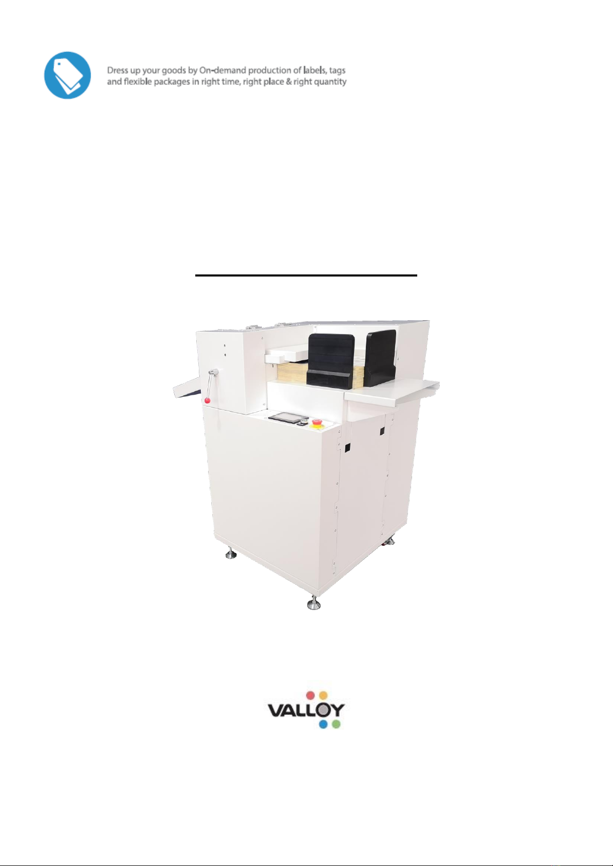
(4) People including operators and maintenance technicians should know the location of emergency stop
button and realize its function and method.
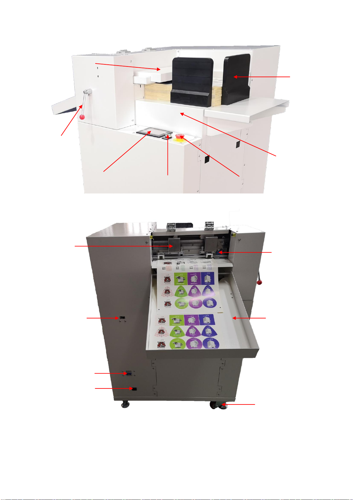
< PICTURE 1-1 >
2. Electric power safety
First of all, make sure all button switches on the machine stand are closed and the ground connection is properly
connected. The power supply used by this unit is 1220V. Circuit breaker needs to be 10A for the main power of this
machine. The Circuit breaker should be in compliance its safety relevant standards.
3. Safety when handling the installation:
To improve the efficiency of the machine, the installation site should be well-ventilated, with good ambient
air quality, and the ambient temperature must not exceed 50 degrees. Avoid rain and direct sunlight.
The following precautions when handling the installation;
(1) Make sure the ground strength is sufficient to support the machine.
(2) Lifting of the machine by lifter should be done by professional operator.
(3) When lifting the machine, nobody is allowed to be under or near the machine.
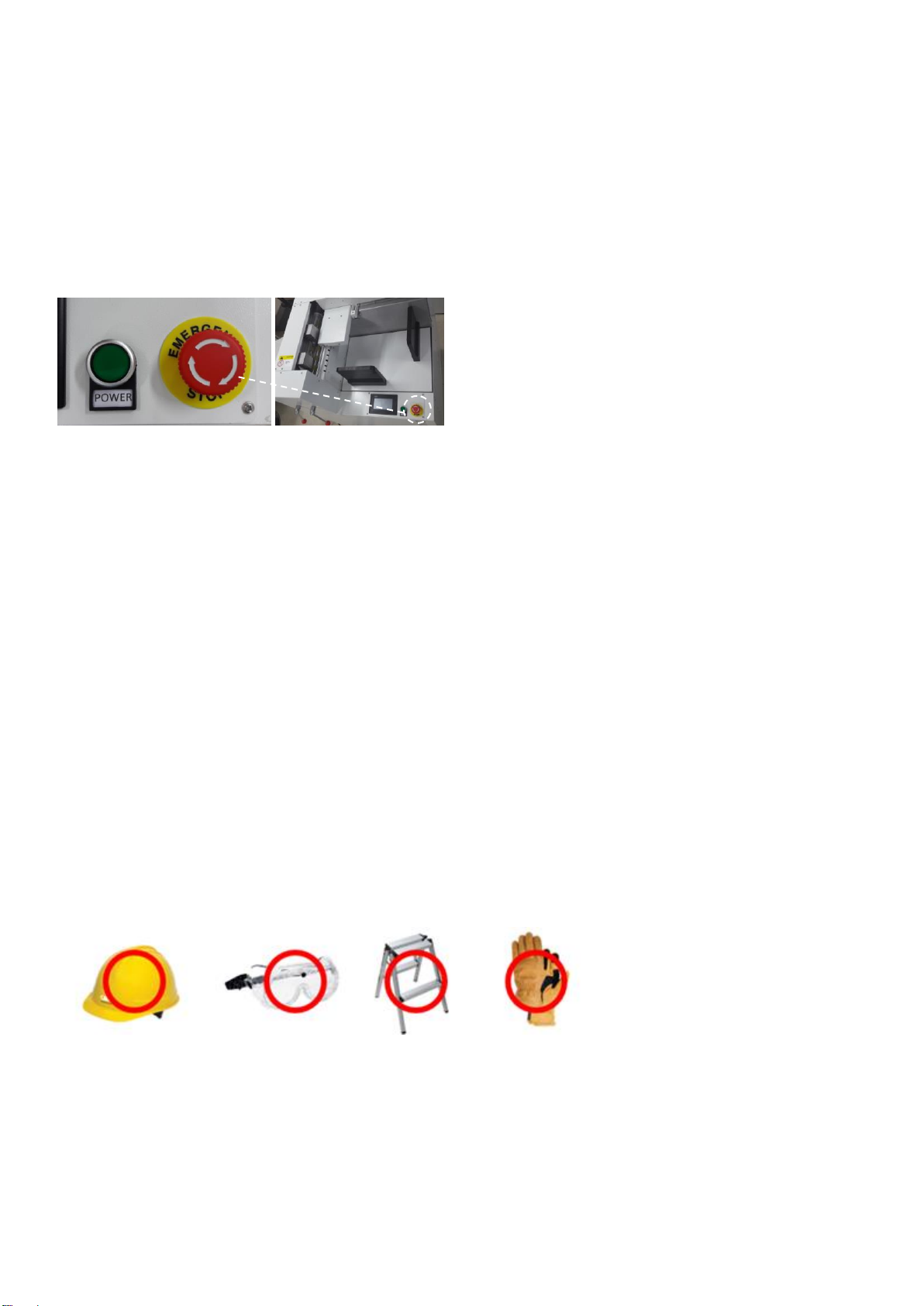
(4) A safety Helmet is required during handling, installation or cleaning.
(5) If it is necessary to reach upper parts on the machine, use a safe and sturdy ladder or platform.
(6) Use a suitable lifting device to lift a heavy object.
(7) Be sure that lifting wire rope is strong enough to handle the weight of the machine or related parts.
(8) Please turn off the power before carrying or installing. If you need to turn on the power, please let other
people know the location of the emergency stop switch in advance.
(9) Wear leather gloves or similar protective equipment when handling, installing or cleaning.
< PICTURE 1-2 >
4. Precautions during operation:
The operator should be familiar with machine’s functions, characteristics and operation methods.
Do not let other untrained people approach to the machine. During running, stretching of hands into the working area
is strongly prohibited. If there is any abnormal situation happening, turn off the power or press emergency stop button
immediately. After that try to find the solutions. Safety precautions during operation are as follows.
(1) Do not remove any safety shields and safety measures.

Pag 5
(2) Do not remove or change the position of the interlock mechanism.
(3) Do not touch the switch with wet hands.
(4) Do not place any part of the body on the moving part of the machine or beside it.
(5) Keep your hair away from machine moving parts.
(6) Do not wear bracelets, watches, jewelry, or loose clothing.
(7) Generally, one operator is required for this machine. If more than one operator is working on the machine, there
should be good communication between operators.
5. Precautions for maintenance:
Always turn off the power supply during maintenance.
Safety precautions during maintenance are as follows;
(1) Turn off the main power before inspection or maintenance.
(2) Maintenance or inspection should be carried out by authorized technician.
(3) It is prohibited to climb the machine.
(4) Please use the recommended lubricant or grease.

Pag 6
1-2 Warning Label Description
Keep door closed. Rolling gears, chains, belts and pulleys
inside which may cause personal injury.
Be away from rolling parts like rollers or belts of running
machine, which may cause personal injury
Do not touch the machine by hands during machine is
running.
Be sure to connect the ground wire at installation of the
machine.
Be cautious not to be electrically shocked.

Pag 7
1-3 Safety Instructions
Do not touch the knife tip with your finger.
This can cause your finger to be injured.
Do not damage or modify/change original power cable. Do
not make the power cable excessively bent, pulled,
bundled, or pressed under heavy objects. This will damage
the power supply, resulting in electric shock or fire.
If you do not use the machine for a long time, please
unplug the power cable from the wall socket. Otherwise it
may cause a fire.
When operating, hands must not be placed near from the
moving or rolling object of the machine. This will cause
harm.
When unplugging the power cable from the wall socket, you
should pull the plug, should not pull the cable. Strong
pulling of cable can cause electric shock or fire.

Pag 8
Chapter II Transportation and Installation
2-1 Crate handling
When transporting wooden boxes, use a forklift with a carrying capacity of 500kg or more.
2-2 Packing and Unpacking
Packing : When packing, fix the four wheels of the machine first, and then lower the pads to keep the
balance and prevent movement or sliding.
Unpacking : The reverse of the packing process.
2-3 Storage conditions
Storage temperature : The machine can be stored at 0 to 40 degrees
Storage humidity : The machine can be stored at 30~90%
2-4 Machine handling
When the machine is being transported, raise the floor mat first, then you can drag or push the machine on
its wheels. When you encounter uneven ground, you need to use a forklift or hydraulic vehicle to carry the
machine.
2-5 Space requirements
Length: 2 meters Width: 1.5 meters Height: 2 meters.
2-6 Electrical specifications
The voltage used by this station is single phase 220V, 50/60Hz. Use proper transformer for 110V power.
2-7 Installation Procedure
1. Move the machine to a stable load-bearing ground.
2. Use a hydraulic truck to raise the machine and drop the four feet.
3. Use spirit level check the level of 4 feet to setup the machine in stable status on the floor.
2-8 Disassembling
The reverse of the installation process.
* No need of air compressor or blower for this machine.

Pag 9
Chapter III System Introduction
3-1 Packing list
After opening the package, first check the following attachments. If any of them are missing, please contact
the seller or the company.
No.
Item
Quantity
Icon
1
Power cable
1
2
Keys
2
3
Magnetic guide
plates
2
4
Software and
Video Manual
CD + USB Lock
Key
1
3-2 System parameters
Machine name
DuoBlade F Digital die cutting machine (DB340F)
Maximum paper width
340mm
Maximum paper length
570mm
Maximum label width
340mm
Minimum label width
10mm
Maximum label length
500mm
Minimum label length
10mm
Cutting speed
3m/s (according to die cut content)
No. of Die cutting head
2 ea
Die cutting technology
Carbide rotary cutter
Die cutting accuracy
0.1MM (repeat)
Die positioning
Manual, black mark single or double
Size
91cm(W) x 85cm(D) x 117m(H)
Weight
About 120KG
Power supply
220VAC, 1000 watts
Warranty service
양식의 맨아래
One year (except for wearing parts)

Pag 10
3-3 DuoBlade F (DB340F) Digital Die Cuter Parts Description
(Structural components schematic)
< PICTURE 3-1 >
< PICTURE 3-2 >
1
2
3
4
5
6
7
9
10
11
12
14
8
13

Pag 11
No.
description
No.
description
1
Emergency stop
2
switch
3
control panel
4
Pressing lever
5
Feed elevator
6
Cardboard
7
Suction suction module
8
Double knife assembly, slider assembly
9
Data transmission port
10
Main power switch
11
main power port
12
Casters
13
Paper bucket
14
Marking sensor

Pag 12
Chapter IV Preparation
4-1 Mark Sensor Setting
< PICTURE 4-1 >
When installing the label media, make sure that the sensor is properly installed and the sensitivity of the
sensor is well-adjusted to recognize the mark correctly. Make sure that the green indicator light is on when
the sensor is looking at the blank white space, and the yellow and green indicator lights are on when the
sensor is looking at the black mark.
1. Calibration of mark sensor
The mark sensor is moving together with the cutting heads. It detects the black mark on the material and
recognizes exactly where to begin cutting. Move the mark sensor and place the sensor's light spot at the
center of the black mark. Usually we use 4 mm x 4 mm square black marks.
If you are using dark-colored marks on a light background media, set the D/L switch to "L" (light) position.
Move the white background into the sensor’s focus. Rotate the adjusting knob to starting position of "+"
(the right limit position). Turn the adjusting knob to the "-" direction until the yellow LED goes out. Keep
this as position 1. Then move the black mark into the sensor focus (the yellow LED lights up again) and
continue turning the adjusting knob in the "-" direction until the yellow LED is extinguished again (position
2). Rotate the knob back and set it between positions 1 and 2 to have in optimal position between
switching threshold.
< PICTURE 4-2>
Mark sensor

Pag 13
If you are using dark colored media with light colored mark, set the D/L switch to "D" (dark) position.
Move the sensor’s focus on the light-colored mark first. Rotate the adjusting knob to starting position of "+"
(the right limit position). Turn the adjusting knob in the "-" direction until the yellow LED goes out. Keep
this as position 1. Then move the dark background to the sensor’s focus (the LED lights up again) and
continue rotating the adjusting knob in the "-" direction until the yellow LED turns off again (position 2).
* Tip : The yellow LED will be lighted when sensor focus is on dark color. When sensor is acting in
opposite behavior, change the HD switch on the other direction.
4-2 Cutting head installation
There are many kinds of cutting blades. Select the cutting blade that best suits the media to be cut.
Cutting blade
Part number
Diameter
and offset
Compatible
knife Holder
Applications and features
VD 09U
ø0.9 mm
0.45
VD340-09U
Cut color stickers standard blade. Suitable
for cutting 0.25 mm thick media.
Cutting length: about 4000 m
VD 15U
ø1.5 mm
0.75
VD340-15U
Can cut thicker media than VD09U can
cut. Suitable for cutting media from 0.25
mm to 0.5 mm thickness.
1. Knife structure
The cutting machine uses a cutting blade mounted in the knife holder for
cutting. There are two different tool holders to fit the diameter of the installed
blade (the 0.9 mm tool holder provides the standard tool holder). Be sure to
install the cutting blade to the correct knife holder as shown in Figure 4-3.
< PICTURE 4-3 >

Pag 14
2. Replace cutting blade
See Figure 4-4~4-5 and carefully hold the blade to avoid cutting yourself
< PICTURE 4-4 >
< PICTURE 4-5 >
Step 1 - Rotate the blade length adjustment knob to retract the blade back to the knife
holder as shown in Figure 4-6.
< PICTURE 4-6>
Step 2 - Rotate the knife holder counterclockwise to remove it from the knife holder.
Step 3 - Remove the blade from the holder cap.
Step 4 - Insert the new blade into the hole in the holder cap.
Step 5 - Insert the blade into the holder cap and tighten the holder cap.
3. Adjust the blade length
If the blade protrudes longer than the thickness of the media to be cut, it can damage the cutting pad.
Be sure to adjust the blade length correctly.
Step 1 - Rotate the blade length adjustment knob to adjust the blade length. The blade extends in the
direction of "A" and retracts in the direction of "B". Spin for each rotation of the knob, the blade moves
approximately 0.5 mm. See Figure 4-7.

Pag 15
< PICTURE 4-7>
Step 2 - First align the tip of the cutting tip with the tip of the cutting tip, and then extend the blade from
this position depending on the thickness of the media to be cut.
Step 3 - Assuming the face paper thickness is "t" (as shown in Figs. 4-8), the blade length "l" should be
equal to or slightly longer than "t".
"l" must not exceed the total thickness of the face paper and its base paper. If you cannot accurately
determine the thickness of the tissue, increase it little by little to adjust the knife.
The length of the blade until the blade leaves only traces on the base paper after cutting.
< PICTURE 4-8>
Step 4 - Loosen the pen holder screw and attach the cutting knife. After the cutting knife is correctly
positioned, tighten the pen holder screw, as shown in Figure 4-9.
< PICTURE 4-9 >

Pag 16
4-3 Material Preparation
Sort out material sheets evenly and place on the lifting platform of the die-cutting machine. The black mark
of the material needs to be on the left side. Fix the upper left corner of the material to be aligned with the
upper left corner of the machine and use 2 magnetic plates to fix the other two sides. See picture 4-10.
< PICTURE 4-10 >
Then start the system. Click on the screen to reset and enter the number of sheet to cut. If you are using
double knives at the same time, you need to adjust the distance between the heads on the control panel.
After sending a file from a computer or reading a file from a USB flash drive, the lifting platform of the die-
cutting machine will rise till top material’s touching the upper limit sensor. The suction belt delivers the top
sheet of material to the cutting platform automatically.
4-4 Die Cutting Preparation
Use left, right, up and down arrow keys on the control panel, make the beam focus the target sensor on the
black mark and check if the yellow light is on, as shown in Fig. 4-11. Then press OK button to start die-
cutting job.
< PICTURE 4-11 >

Chapter 5. System Operation Instructions
5-1 Panel operation instructions
1. Power button: The machine power is on.
2. Emergency stop button: All motors stop working and only system work.
After starting the system, tap the screen to enter the main program, the machine will automatically reset, and click on the numerical display area to change
the value.
No.
Parameters
Parameter
Setting Range
Parameter Description
On-screen display
1
Cut J.
1~30000
The number of cuts for the selected job
Track J.
0~30000
The number of interval between each sensing of the mark. If the value is 0
or 1, it senses each mark. If the value is 2, it senses every 2nd mark. More
value increases production speed but decrease accuracy.
Last Jobs
1~30000
Showing number of cuts of the last job
Track M.
No Mark, Single
Mark, Double
Mark
Mark sensing mode. No Mark means no sensing of mark for blank cut jobs.
Single Mark means it senses left-bottom mark only. Double Mark means it
senses left-up mark and left-bottom mark together for better accuracy.
Settings
Moves to Settings window. (Ref. No. 2)
Test
Additional functions like Manual Setting (Ref. No. 7)
D. Head
30~110
The distance between the two knives when using dual knife cutting.
If you want to set over 110, move 2nd holder to another side of head.
Distance of two hole is 80mm.
Reset
It is recommended to use this button to RESET the memory after finishing
each job, before loading a new job.
Repeat
Recall the previous working job from the memory. After rebooting the
machine, previous job data will be removed.
2
Parameter
Adjustment of parameters like head offset, scale and angle (Ref. No. 3)
Tools
Tool settings like mark size, cutting area size, mark color and etc. (Ref. No.
5)
Factory
Reset
Restore to the initial factory settings (Note: Record the current parameters
before restoring to the factory settings)
Speed
Showing speed related parameters (Ref. No. 4)
Data Trans
Showing settings for file transfer modes and port / IP settings (Ref. No. 6)
Tools Select
Showing options to turn ON / OFF for the heads to use
Back
Click to return to the previous menu

No.
Parameter
Name
Parameter
Setting Range
Parameter Description
On-screen display
3
X1 vert.
-10000~10000
Based on the origin, change the X direction
vertical angle (unit 0.1% degree) for single mark
track mode
-10000 10000
Y1 vert.
-10000~10000
Based on the origin, change the Y direction
vertical angle (unit 0.1% degree) for single mark
track mode
10000
-10000
X2 Vert.
-10000~10000
Based on the origin, change the Y direction
vertical angle (unit 0.1% degree) for double mark
track mode
-10000 10000
Y2 Vert.
-10000~10000
Based on the origin, change the X direction
vertical angle (unit 0.1% degree) for double mark
track mode
10000
-10000
X scale
-10000~10000
Every increment or decrease, the X direction
image is enlarged or reduced by 0.01%
Y scale
-10000~10000
Every increment or decrease, the Y direction
image is enlarged or reduced by 0.01%
X Cut Ad.
-300~300
X offset distance of the knife relative to the origin,
in unit of 0.01 millimeters
Y Cut Ad.
-300~300
Y offset distance of the knife relative to the origin,
in unit of 0.01 millimeters
4
Cut speed
1~1600
Change cutting speed (in mm/s unit) when moving on straight line (Higher
value, faster speed) Max. value is 1600 mm/s.
Cut Acc.
1~300
Change acceleration level of cutting speed (Higher value, faster
acceleration)
Null Speed
1~1600
Change the cutter’s moving speed (in mm/s unit) between label and label
without cutting (value is high, speed is fast) Max. value is 1600 mm/s.
Null Acc.
1~300
Change the cutter’s moving acceleration between label and label without
cutting (Higher value, faster acceleration)
Turn speed
0~100
Change cutting speed when moving on curves (Higher value, faster speed)
* Slow down the speed in cutting of circles and polygons, less than 20.
Feed Speed.
1~10
The speed of feeding belt. Higher value feeds the media faster.
O.P. Speed
1~50
The speed of media discharging. Higher value pushes the media out faster
after job completion.

No.
Parameter
Name
Parameter
Setting Range
Parameter Description
On-screen display
5
Cut Ad.
0~100
Change the radius value of knife tip turning at corner. The
unit is 0.025mm.
Note: when you use software settings instead, please use 0
or near 0 value.
Cut P. Ad.
-1000~1000
When you change from Default value, it adjusts gap between heads
precisely. At reset, 2nd head moves to CutD Com distance and coming back
to Cut Dir distance. So Cut Dir value cannot exceed CutD Com value.
Cut D. Time
0~10000
Time delay of cutting after knife falls (in unit of ms)
Load D. T
0~100
Start time delay of feeding belt after top media touches the feed limit
sensor. (in unit of ms)
D. S. Len
0~100
Limit the acceleration and speed for the small lines to have better accuracy.
(Very sensitive parameter, so no modification is recommended.)
Model No.
Model Number
Language
Chinese/English
Select GUI language
Mark length
0~100
Unit is ‘mm’, set mark length, 4mm as default.
Mark width
0~100
Unit is ‘mm’, set mark length, 4mm as default.
Find Input
B/W
Select Black or White, set track sensor’s mark color
Send Input
B/W
Select Black or White, set feeder sensor’s mark color
X Length
0~10000
X direction cutting range in mm unit.
(Use higher head pressure for larger area to cut)
Y Length
0~10000
X direction cutting range in mm unit.
SP Factor
Mechanical settings of factory design, no modification is recommended.
X/Z Shift
Mechanical settings of factory design, no modification is recommended.
6
Transfer M.
Serial port,
network port,
USB memory
Select the transfer mode to use, change the transfer mode to take effect
after restart
Network P.
Set the port number consistent with the PC of the installation device
operating software
Network ID
Set the local IP address
Target ID
Enter the IP address of the installed PC operating software PC
Read USB
disk
Use USB memory mode to read files
Note: (USB memory mode cannot be used in split-cut mode)

No.
Parameter
Name
Parameter
Setting Range
Parameter Description
On-screen display
7
Blade P.1
400~1000
The larger the setting, the greater the knife pressure, unit: gf/cm2
Blade P.2
400~1000
The larger the setting, the greater the knife pressure, unit: gf/cm2
HS / LS
High speed/low
speed
Speed of heads when moving manually (e.g. finding marks)
ARROW
BUTTONS
up down left
right
Move the head or sensor by using the arrow keys
Old T
Pre-factory equipment test mode (users do not need to operate)
Back
Return to previous menu
Table of contents