2. УХОД
Гарантией правильной работы смесителей, оснащенных
керамическими регуляторами потока, является чистая
вода, то есть вода, не содержащая таких примесей, как
песок, накипь и т.д. В связи с выше изложенным,
обязательным условием является оснащение
водопроводной сети сетчатыми фильтрами, а в случае
отсутствия такой возможности – индивидуальными,
предназначенными для смесителя, запорными
клапанами с фильтром.
●
Návod na montáž a obsluhu ▪ Návod na montáž a obsluhu
2455.70/IO 7
PL EN DE RU CZ SK
Instrukcja obsługi i montażu▪Assembly and operation instructions ▪ Gebrauchs-und montageanleitung▪Инcтрукция по монтажу иобслуживанию
Rev. 1 September 2018
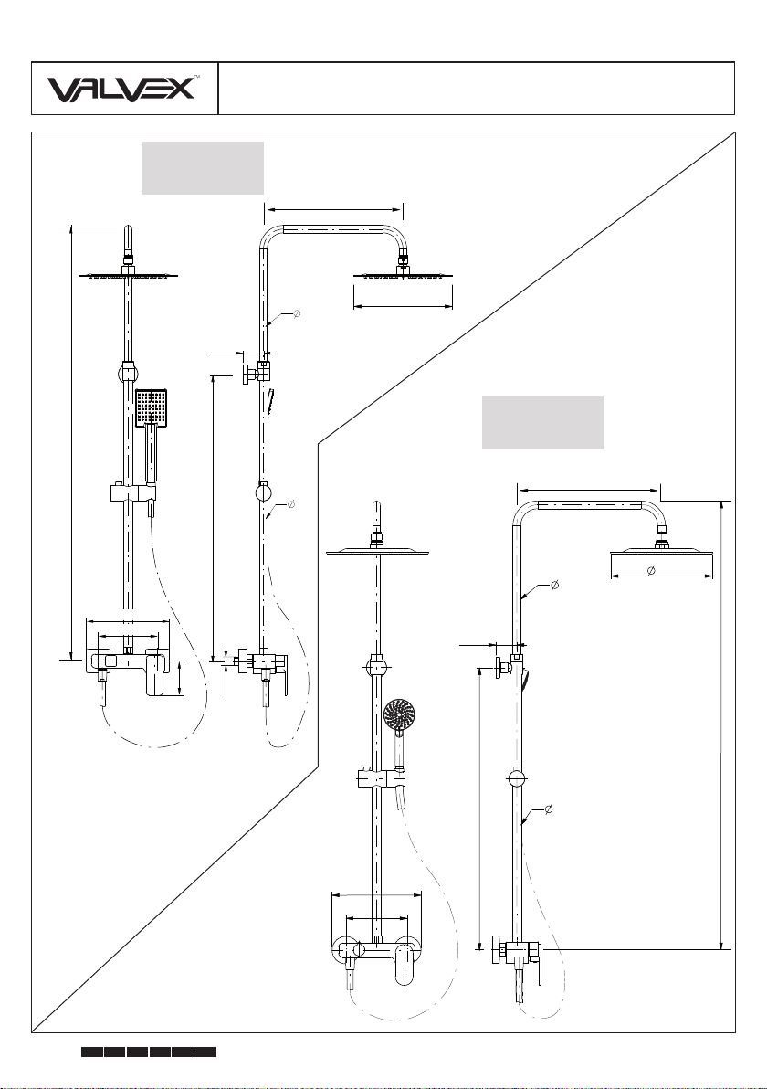
KOLUMNA PRYSZNICOWA ▪ SHOWER COLUMN ▪ DUSCHSÄULE
ДУШОВАЯ КОЛОННА ▪ SPRCHOVACÍ KOLONA ▪ SPRCHOVACIA KOLÓNA
В случае затрудненного переключения смесителя
нельзя прикладывать чрезмерного усилия на рычаг, так
как это может повлечь за собой повреждение регулятора
потока. В данном случае следует снять регулятор и
очистить его от скопившихся загрязнений.
●
При сильных загрязнениях рекомендовано применять
чистящий крем (молочко) типа Cif, DIX и т.д.
Ни в коем случае нельзя чистить поверхность смесителя
тряпками из грубого шероховатого материала или
чистящими средствами, содержащими абразивные
материалы и кислоты.
Для очистки элементов, изготовленных из пластмассы и
покрытых лаком, нельзя использовать средства,
содержащие спирт, дезинфицирующие вещества,
растворители и сильные щелочи.
CZ
1. MONTÁŽ
Na třmen směšovače nasaďte páku (17) a dotáhněte
upevňovací vrut (18) imbusovým klíčem (A) přiloženém k
soupravě, (obr. 2),
k přítokovému potrubí s vnitřím závitem G1/2 zašroubujte
excentrické přípojky, spojení utěsňujte konopným vláknem
(nebo jiným těsnícím materiálem, např. teflonovou páskou);
dbejte při tom na to, aby soby excentrických otvorů ze strany
závitu G3/4 byly ve stejné výšce, čelní plochy ve stejné
vzdálenosti od stěny a vzdálenost otvorů se rovnala
vzdálenosti od přípojných matic tělesa baterie (obr. 3.1),
na excentry (13) našroubujte růžice (12) (obr. 3.2),
do přípojných matic uložte těsnění (11) a našroubujte je na
excentry (obr.3.3),
vyvrtejte otvor o průměru 6mm, hloubce 20mm, (pokud
vrtáte v keramických obkladových prvcích použijte zvláštní
vrták). Následně do připravených otvorů zasuňte hmoždinka
(3), nakonec pomocí vrutů (5) připevněte držák (4) do stěny
(obr. 4.1),
našroubujte matici (7) na přepínač (10), následně nasaďte
připevňovací matici na držák (4), nakonec utáhněte pojistný
●
●
●
●
●
●
Pro montáž baterie použijte klíče s hladkým netěsnícím
povrchem čelistí, případně použijte umělohmotné krytky chránící
povrch matic před poškozením.
POZOR: Než přistoupíte k instalaci míchače ujistěte se, že osy
armatur na potrubí přivádějícím vodu směřují kolmo k rovině
stěny. Pokud provedete spojení způsobem, který neodpovídá
tomuto pokynu, může dojít k popraskání či poškození excentric-
kých spojů, buď během instalace nebo během provozu míchače.
Очистка внешних покрытий:
Для устранения грязи и пятен следует применять
исключительно нейтральные чистящие средства,
предназначенные для очистки арматуры, а также воду.
Следует соблюдать правила использования
применяемого чистящего средства. Для удаления
накипи использовать уксус, после чего промыть
поверхность чистой водой и вытереть досуха тряпкой.
●
●
●
●
2. ÚDRŽBA
Zárukou pro řádnou funkčnost baterií, které jsou opatřeny
keramickými kartušemi pro regulaci průtoku, je čistá voda, to
znamená taková, která neobsahuje nečistoty, např. písek,
kotelní kámen atd. V souvislosti s výše uvedeným je
nezbytné, aby vodovodní instalace byla vybavena sítkovými
filtry a v případě, že to není možné, individuálními uzavírací-
mi ventily s filtrem, které jsou určeny pro baterie.
V případě zvýšeného odporu při regulaci průtoku se
nesnažte vyvíjet větší tlak na páku, protože může dojít k
poškození kartuše pro regulaci průtoku. V takové situaci
musíte vymontovat kartuši pro regulaci průtoku a odstranit
nečistoty, které se v ní nahromadily.
●
●
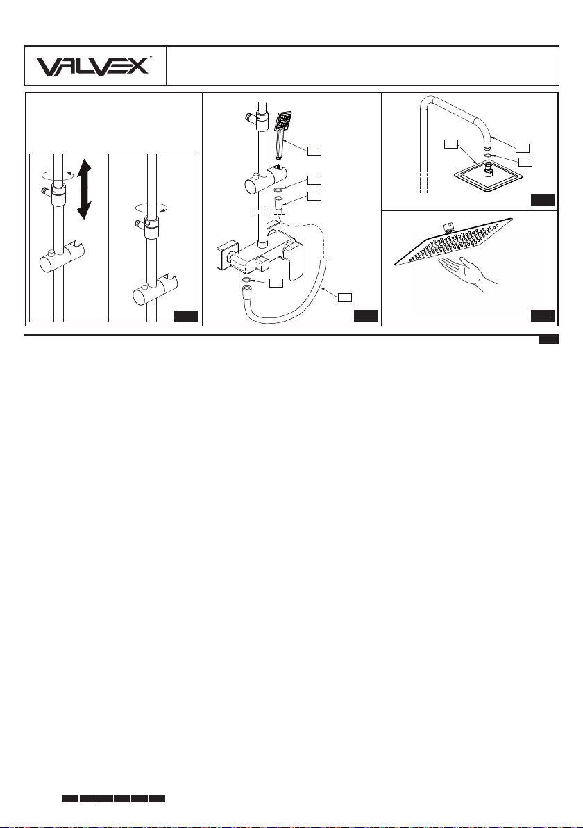
Вложить душевую трубку (15) в передвижную ручку (pис.
6),
На конец прикрутить душевую головку (14) к душевой
трубе (1) (рис. 7),
После монтажа проверить плотность соединений.
nšroub (2) (obr. 4.2, 4.3),
nasaďte těsnění (9) do šestihranné matice hadice (16),
následně našroubujte nátrubek z přepínače (10). Na druhý
konec hadice našroubujte sprchové sluchátko (15). Nasaďte
sluchátko (15) na nastavitelnou tyč (obr. 6),
nakonec našroubujte sprchovou růžici (14) na sprchovou tyč
(1) (obr. 7),
zkontrolujte těsnost spojeni.
●
●
●
Čištění vnějšího povrchu:
K odstraňování nečistot a skvrn používejte pouze neutrální
čisticí prostředky, které jsou určeny k čištění armatur, a
vodu. Dodržuje návod k použití daného čisticího prostředku.
K odstranění vodního kamene použijte ocet, potom povrch
opláchněte čistou vodou a vytřete dosucha hadříkem.
●