Panel: maximum dimensions 1800x1100 mm (21 kg) Panel: maximum dimensions 2100x1100 mm (24 kg)
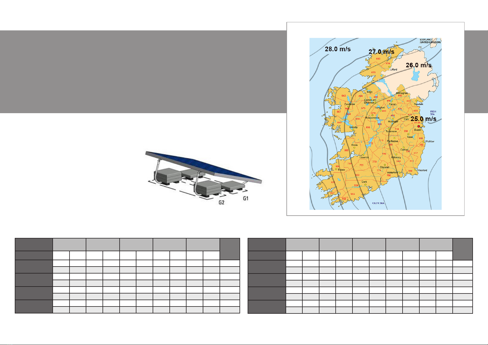
Windmap Germany
Required ballast | Germany
General
The ValkBox3 mounting system must be reinforced by means of tiles, which must be placed on the
indicated ballast foundations. In three steps you can easily calculate the required ballast;
• determine the wind area on the windmap
• choose the wind area and building height in the table
• you can now read the number of tiles / kg
Note 1: Min. extra ballast in G1 & G2 has to be 2 x 1 tile (2 x 9 kg).
Note 2: The ballast in G1 & G2 must be equally divided over the rubber ballast carriers.
Note 3: The max. of 20 tiles (4 in G1 and 16 in G2) can be placed for extra ballast (180 kg).
Building height 0 - 5
meter
5 - 7
meter
7 - 9
meter
9 - 12
meter
12 - 15
meter
Wind area G1 G2 G1 G2 G1 G2 G1 G2 G1 G2
1 (22,5 m/s) 36,0 39,0 36,0 39,0 36,0 39,0 36,0 39,0 36,0 39,0 kg
4,0 8,7 4,0 4,5 4,0 4,5 4,0 4,5 4,0 4,5 tiles
2 (25 m/s) 36,0 53,0 36,0 53,0 36,0 53,0 36,0 53,0 36,0 53,0 kg
4,0 6,0 4,0 6,0 4,0 6,0 4,0 6,0 4,0 6,0 tiles
3 (27,5 m/s) 36,0 68,0 36,0 68,0 36,0 68,0 36,0 68,0 36,0 68,0 kg
4,0 8,0 4,0 8,0 4,0 8,0 4,0 8,0 4,0 8,0 tiles
4 (30 m/s) 36,0 84,0 36,0 84,0 36,0 84,0 36,0 84,0 36,0 84,0 kg
4,0 9,5 4,0 9,5 4,0 9,5 4,0 9,5 4,0 9,5 tiles
Building height 0 - 5
meter
5 - 7
meter
7 - 9
meter
9 - 12
meter
12 - 15
meter
Wind area G1 G2 G1 G2 G1 G2 G1 G2 G1 G2
1 (22,5 m/s) 36,0 48,0 36,0 48,0 36,0 48,0 36,0 48,0 36,0 48,0 kg
4,0 5,5 4,0 5,5 4,0 5,5 4,0 5,5 4,0 5,5 tiles
2 (25 m/s) 36,0 64,0 36,0 64,0 36,0 64,0 36,0 64,0 36,0 64,0 kg
4,0 7,5 4,0 7,5 4,0 7,5 4,0 7,5 4,0 7,5 tiles
3 (27,5 m/s) 36,0 81,0 36,0 81,0 36,0 81,0 36,0 81,0 36,0 81,0 kg
4,0 9,0 4,0 9,0 4,0 9,0 4,0 9,0 4,0 9,0 tiles
4 (30 m/s) 36,0 100,0 36,0 100,0 36,0 100,0 36,0 100,0 36,0 100,0 kg
4,0 11,5 4,0 11,5 4,0 11,5 4,0 11,5 4,0 11,5 tiles
X= the required ballast is higher than will t under the system. The system must be mechanically attached to the roof. Please contact Van der Valk Solar Systems.
* If you use tiles of different sizes and thus another weight, you need to adjust the number of tiles to get the right weight.
Environmental factors
Position Middle zone roof
Terrain category IV (city)
Height above sea level 350 m
Exclusief North German Lowland
Roof materials Bitumen
Ballast foundations