Van Walt Rain Gauge User manual

Operating Instructions
Van Walt Ltd | Prestwick Lane | Grayswood | Haslemere | Surrey | GU27 2DU | Tel. 01428 661 660 | Fax. 01428 656 808 | www.vanwalt.com
Rain Gauge
1
VAN WALT
Monitoring your needs
MA143V3_02/06/2020_TD
Contents
Introduction ................................................................................................................................
1. Description ........................................................................................................................
1.1 Package contents ...........................................................................................................
1.2 General .............................................................................................................................
1.3 Datalogger .......................................................................................................................
1.4 Measuring section ............................................................................................................
2. Technical specications ..................................................................................................
3. Taking into use ..................................................................................................................
3.1 Settings ..............................................................................................................................
3.2 Connection ......................................................................................................................
3.3 Installation .........................................................................................................................
4. Use ..................................................................................................................................
4.1 LDM e+ ..............................................................................................................................
4.2 Taking rain measurements ..............................................................................................
5. Applications ......................................................................................................................
6. Problems and solutions ....................................................................................................
7. Maintenance ...................................................................................................................
Appendix; Battery set e+ logger ...............................................................................................
2
2
3
3
3
3
4
4
4
6
8
15
15
16
17
18
19
22

Operating Instructions
Van Walt Ltd | Prestwick Lane | Grayswood | Haslemere | Surrey | GU27 2DU | Tel. 01428 661 660 | Fax. 01428 656 808 | www.vanwalt.com
Rain Gauge
2
VAN WALT
Monitoring your needs
Introduction
The e+ RAIN sensor consists of a datalogger and a separate rain gauge sensor. This manual
describes how to use the datalogger and the rain gauge and what their various functions are. A
description is provided of how to use the Logger Data Manager® (LDM) e+ software. It includes
a guide to the preparation of the software and explains various aspects of its use. This is followed
by a description of the various possibilities available for carrying out rain
measurements. It concludes with instructions for calibration and regular
maintenance.
1. Description
1.1 Package contents
0 e+ RAIN sensor, which consists of a datalogger (11.41.21.01), rain
gauge (11.41.21.02), LDM e+ software (11.11.14) and battery set
e+ logger (11.41.90.01)
0 Available separately:
• Stand for the rain gauge for use in the eld (11.41.92.01), includes special
xing nut.
• IrDa readout unit (11.31.90) for wireless connection with a (laptop)
computer
• Readout unit (11.11.10) for connecting with a (laptop) computer
• DRC Readout cable, for connecting to a (laptop) computer by means
of a DRC communication cable (11.11.45). Available in the following
lengths:
5 m
10 m
15 m
30 m
60 m
80 m
100 m
• e-SENSE e+ sensor cable for connecting to an e SENSE SMS modem (eld
modem) available in the following lengths:
1 m
5 m
10 m
15 m
30 m
60 m
80 m
100 m
200 m
e+ RAIN: datalogger, eld
support and rain gauge
(11.11.38)
(11.11.39)
(11.11.40)
(11.11.41)
(11.11.42)
(11.11.43)
(11.11.44)
(11.31.78)
(11.31.70)
(11.31.71)
(11.31.72)
(11.31.73)
(11.31.74)
(11.31.75)
(11.31.76)
(11.31.77)

Operating Instructions
Van Walt Ltd | Prestwick Lane | Grayswood | Haslemere | Surrey | GU27 2DU | Tel. 01428 661 660 | Fax. 01428 656 808 | www.vanwalt.com
Rain Gauge
3
VAN WALT
Monitoring your needs
1.2 General
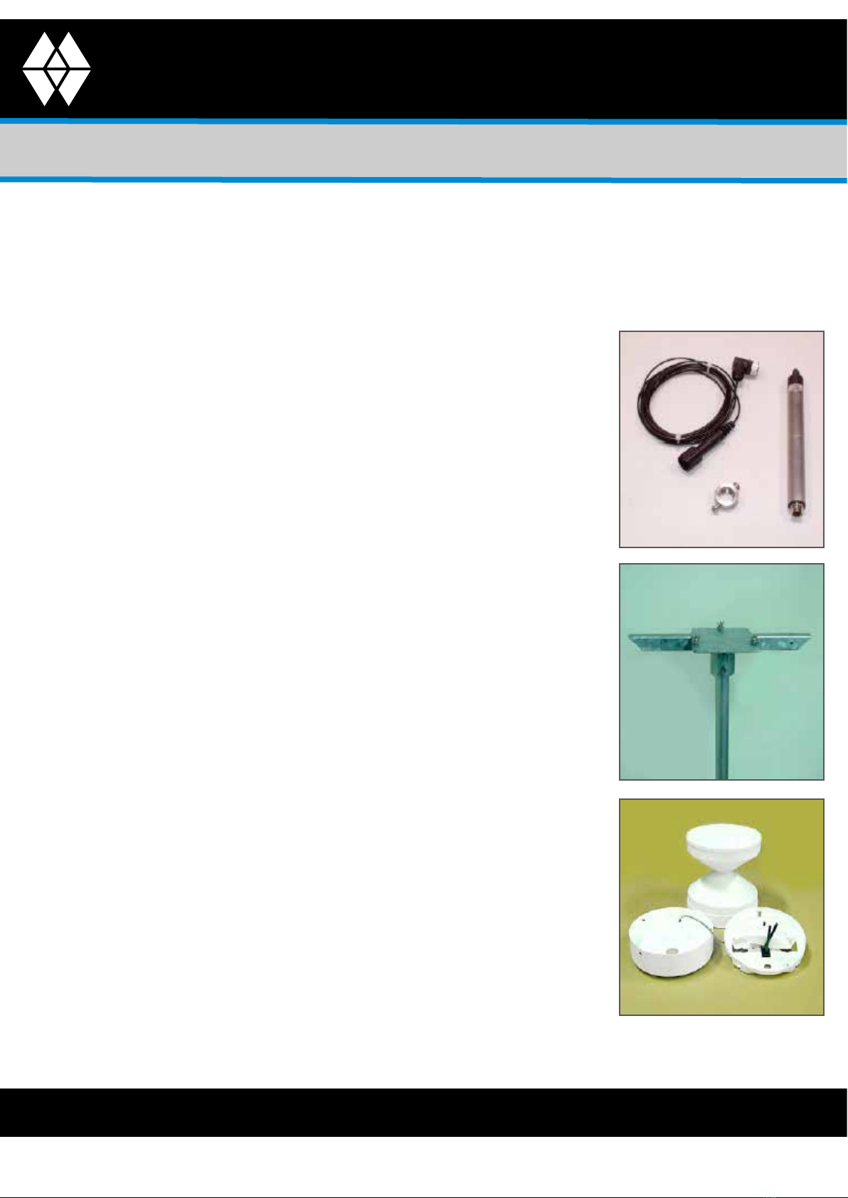
The e+ RAIN sensor is an intelligent sensor that consists of a specic sensor section as well as a so-
called datalogger that houses the micro-electronics. The datalogger has an internal memory for
storing the measurements but also provides the means for reading the digital data. To make this
1.4 Measuring section
The rain gauge is part of the e+ RAIN sensor and is manufactured from UV-proof
synthetic material. It furthermore has an aerodynamic design which ensures
that measurements suffer as little as possible interference from the wind. The
system operates on the so-called ‘tipping bucket’ method, in which rain is
captured via a funnel and poured into a basin that is xed on a hinge. A pre-
determined amount of rain results in the bucket tipping and emptying itself. Brief
contact results with a switch. In this way the amount of rain equals the number of
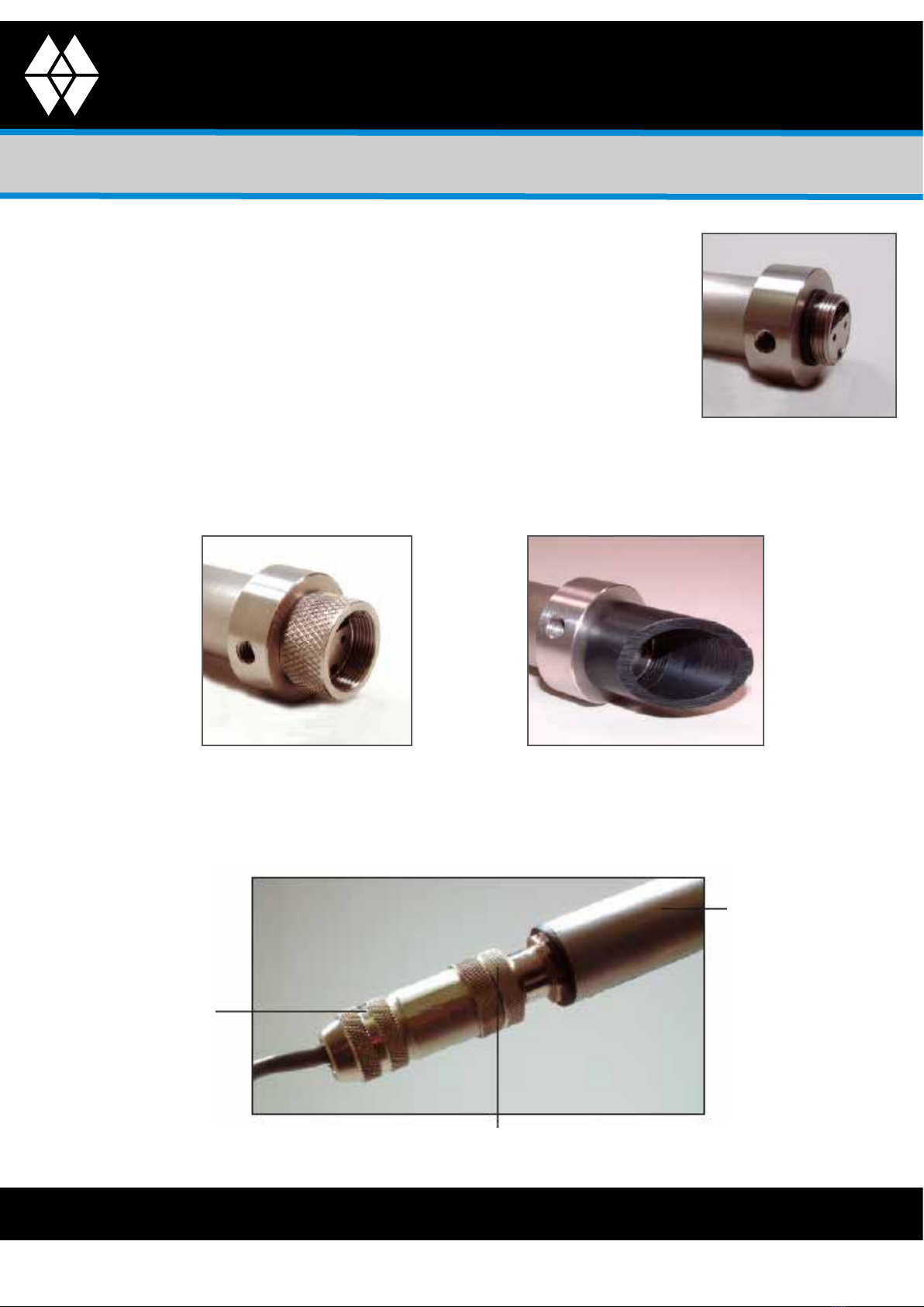
switch contacts during a specic time unit. The rain gauge is tted with a 5-pole
connector for connection with the datalogger.
The raingauges tipping bucket mechanism is immobilised before shipping to prevent damage
in transit. To release the mechanism, remove the funnel from its base by unscrewing the three
thumbscrews. Remove the piece of foam from under the bucket mechanism. This foam may be
saved and used whenever the raingauge is moved
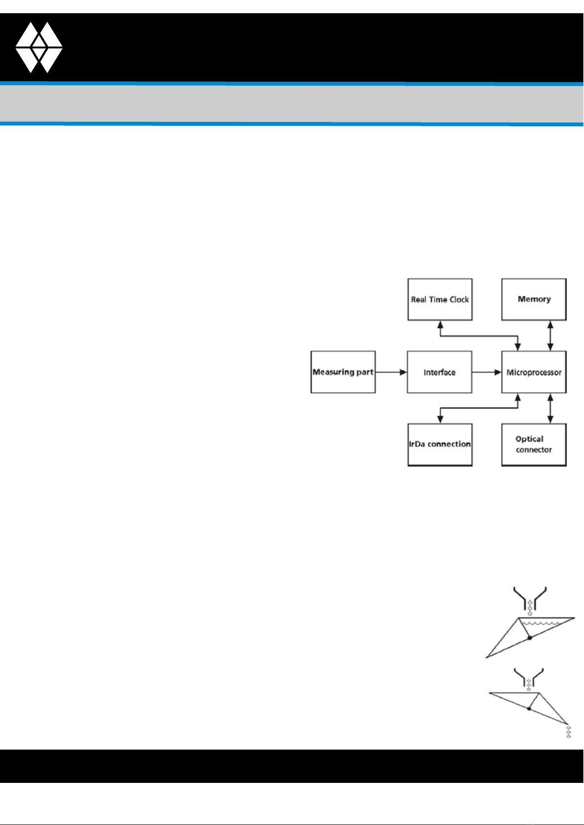
1.3 Datalogger
The datalogger is designed around a
microprocessor that performs the role of saving
periodical measurements in the memory and
enables a connected device to read the stored data. The signal
that the sensor part delivers to the interface is converted into data
that can be processed by the microprocessor. The microprocessor
records the data in the memory with a sample speed, based on the
internal Real Time Clock (RTC). It is possible by means of available communication channels,
namely the optical connector and the IrDa link, for a device that has been connected to
communicate with the microprocessor and read the data stored in the memory or adjust
settings such as the sample speed, for instance. The datalogger of the e+ sensor has 2 measuring
channels and the memory range is divided proportionally over the available channels. The
memory has the capacity to store 30.000 measurements per channel.
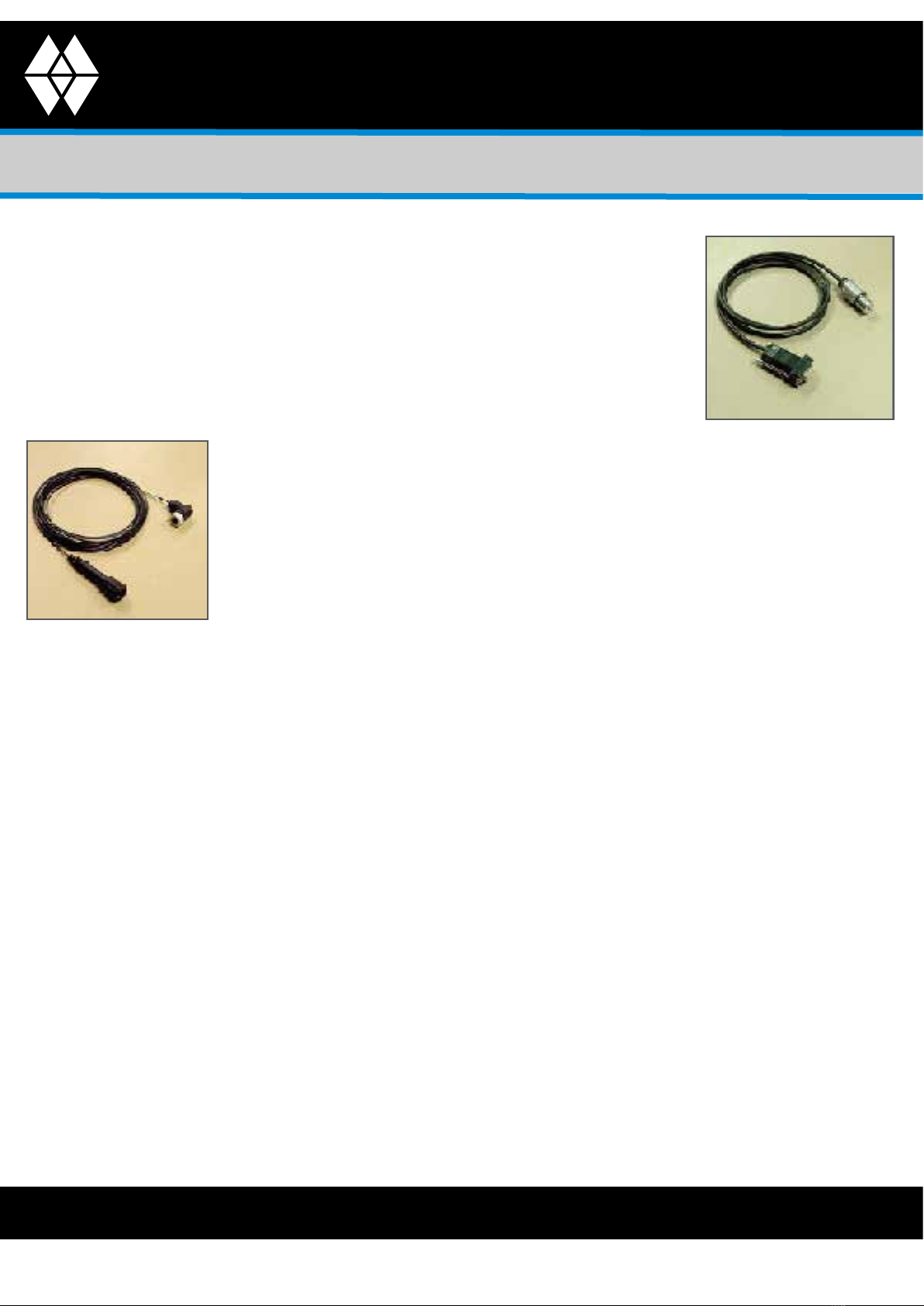
possible the datalogger has an optical connector for a
communication cable or a readout unit or an IrDa interface for
communication by means of an IrDa readout unit. This offers the
advantage of intercompatibility, reliable transfer of data and
the possibility of stand-alone use.

Operating Instructions
Van Walt Ltd | Prestwick Lane | Grayswood | Haslemere | Surrey | GU27 2DU | Tel. 01428 661 660 | Fax. 01428 656 808 | www.vanwalt.com
Rain Gauge
4
VAN WALT
Monitoring your needs
Rain gauge
Diameter rain gauge : 254 mm Height rain gauge
: 340 mm Output signal
: contact
Nominal measurement sensitivity : 0.20 mm rain fall per contact
Maximum contact power : 300 mA Power supply
: None Weight
: 1 kg
3. Taking into use
3.1 Settings
2. Technical specications
Datalogger
Number of channels : 2 channels
Memory capacity : 30,000 measurements per channel
Measurement intervals : 1...60 seconds
: 1...60 minutes
: 1...24 hours
Datalogging method : Measures at chosen times Resolution
: 0.0033%, 15 bit (data storage) Clock accuracy
: <1 sec. per day
Alarm : 0...100% of the measuring range
Battery status : 0 to 100% Temperature operating range
: -20 ... +70 °C Relative humidity range
: 0...100%
Power supply : 3.6 V (AA) lithium battery 2.3 Ah
Battery life : 6 years (typical for 10-minute sample speed)
There is no need to congure any settings before installation of the datalogger. To achieve
optimal measurement precision the datalogger’s factory settings for the range can be used.
The rain gauge is factory-calibrated and is supplied with a calibration specication, which state
the actual measuring sensitivity, the so-called calibration factor. The deviation of this calibration
factor from the nominal sensitivity is 2% at most, which means that the accuracy is always
greater than 2% if the Range setting is not introduced.

Operating Instructions
Van Walt Ltd | Prestwick Lane | Grayswood | Haslemere | Surrey | GU27 2DU | Tel. 01428 661 660 | Fax. 01428 656 808 | www.vanwalt.com
Rain Gauge
5
VAN WALT
Monitoring your needs
To be able to congure the datalogger, the following are required: LDM
e+ software, a readout unit (see Chapter 1.1, “Package contents”) and a
(laptop) computer. LDM e+ is a universal software package, suitable for
the e+ datalogger as well as the Diver® from Van Essen Instruments and
can be used for conguration as well as for reading the data. The LDM e+
is simple to install but make sure the user account for installations under
Windows NT, 2000 or XP has adequate access rights for the installation of
software and that the computer being used has a CD-ROM drive. When the CD is placed in the
CD-ROM drive setup will automatically commence. If this is not the case it can be started by going
to Start -> Run, and enter: <X>:\setup.exe, in which <X> will be the letter indicating the CD-ROM
drive. Next connect the readout unit to an available COM port on the computer. Now launch LDM
e+, press the Application Management tab and enter the following settings options:
• Selected port: should show the number of the port to which the readout unit is connected
• User type: in this case Basic is sufcient, only select Advanced if special settings such as the
datalogger units need to be adjusted
• English / Deutsch / Nederlands: this allows you to select the preferred language.
LDM e+ is ready for the conguration of the datalogger, which should now be placed in the
readout unit.
To enter and adjust settings for
the datalogger the appropriate
window can be accessed by
clicking on the Settings tab in
LDM. Before starting, the current
settings for the datalogger rst need to be
entered. This requires clicking on the button
on the toolbar shown on the right. The left-
hand side of the window shows the general
settings for the datalogger (note: for Diver
settings a slightly different window may be shown). In the right-hand section of the window settings
can be created for the 2 individual measuring channels, including the Range setting referred to
earlier. The gure on the next page illustrates the setting options per channel. For more information
about the calibration of the rain gauge and determining the correct Range setting, please refer to
Chapter 7, “Maintenance”.

Operating Instructions
Van Walt Ltd | Prestwick Lane | Grayswood | Haslemere | Surrey | GU27 2DU | Tel. 01428 661 660 | Fax. 01428 656 808 | www.vanwalt.com
Rain Gauge
6
VAN WALT
Monitoring your needs
Once the setting options have been entered, all the settings will be programmed into
the datalogger by clicking on the button on the toolbar as shown on the right. The e+
sensor is now ready to be installed. It should be noted that it is not necessary with the e+
sensor to stop the datalogger in advance, as the new settings will be activated as soon
as the datalogger is started again.
3.2 Connection
When the installation of the e+ sensor is a permanent one and the
datalogger is located in an easily accessible place, the IrDa-interface
provides a useful alternative to a permanently installed connecting
cable. The IrDa interface has an optical unit that makes it possible for the
datalogger to be read from a distance of 1...2 metres. It is tted with a 9-pole
sub-D connec- tor for connecting to the COM port of a computer. To read
the datalogger’s data in the eld use should be made of a laptop computer.
When it is not possible to have as datalogger and a computer close
together because the e+sensor is being permanently installed, one
can resort to the use of a DRC readout cable in combination with a
communication cable. A DRC readout cable is available in different lengths
and which is tted with a special connector for connection to a DRC
communication cable. It also has an optical interface for the datalogger.
The DRC communication cable comes in a standard length. It is tted with
connector for connection to the readout cable and has a 9- pole sub-D
connector to connect it to the COM port of a computer.

Operating Instructions
Van Walt Ltd | Prestwick Lane | Grayswood | Haslemere | Surrey | GU27 2DU | Tel. 01428 661 660 | Fax. 01428 656 808 | www.vanwalt.com
Rain Gauge
7
VAN WALT
Monitoring your needs
It is common practice in an e-SENSE measuring system for the e+ sensor
to be permanently installed. This requires it to be connected by means of
an e+ sensor e SENSE cable to an e-SENSE SMS modem (eld modem).
An e-SENSE measuring system is designed to carry out remote wireless
transmission of the measurement data from the e+sensors by means of an
SMS modem to a central (Internet) database. This does away with
having to read data in the eld. For further information about e SENSE
measuring systems, the e-SENSE data site or e-SENSE direct and points of
note in connection with the installation, you are referred to the instruction
manual for the e-SENSE SMS modem (eld modem), the e-SENSE data site
and e-SENSE direct. For more information about the types and lengths of
connection cable as well as the IrDa-interface please refer to Chapter 1.1,
“Package contents”.

Operating Instructions
Van Walt Ltd | Prestwick Lane | Grayswood | Haslemere | Surrey | GU27 2DU | Tel. 01428 661 660 | Fax. 01428 656 808 | www.vanwalt.com
Rain Gauge
8
VAN WALT
Monitoring your needs
3.3 Installation
Prior to installation it is important to nd a suitable location for the
rain gauge. In the rst instance one should look for a setting where
the measuring cannot be interfered with by obstacles. A useful rule
of thumb is to position the rain gauge at a height that is at least twice
that of nearby obstacles. In the case of special applications it is
possible that there may be other special requirements. Secondly, it is
important for the rain gauge to be placed in a horizontal position. Also
look for a location where the stand for the rain gauge can be placed
in a stable and horizontal position.
Choosing the right measuring location is of great importance as far as obtaining accurate
measuring results is concerned
First of all the stand for the meter must be placed in a
stable and horizontal position. This will require drilling a
hole in the soil in which to place the tube of the stand.
After putting the tube in position place the leftover soil
back into the hole and tamp it down well while holding
the tube in an upright position. Place the xing platform of
the stand on top of the tube and nish by securing it with
socket-head screws.
The rain gauge is now completely disassembled, after
which it is reassembled step by step back on the stand:
1. Place the outer base plate with the three xing holes on
the platform on the stand.
2. Place the inner base plate with the recesses on the outer base plate. The
recesses need to t correctly into the studs while it must be ensured that
the inner base plate cannot be pushed up by the connecting cable.
3. Align both base plates with the aid of the adjustable rings of the stand.
4. Check the horizontal position with a spirit level that is xed to the inner base plate.
5. Secure the outer base plate by screwing the wing nuts on the stud bolts of the stand.
6. Assemble the rain gauge.

Operating Instructions
Van Walt Ltd | Prestwick Lane | Grayswood | Haslemere | Surrey | GU27 2DU | Tel. 01428 661 660 | Fax. 01428 656 808 | www.vanwalt.com
Rain Gauge
9
VAN WALT
Monitoring your needs
Communication
cable
Protective cap
(optional)
e+ logger
Mounting nut with
vandalism proof
bolts. Delivered with
measuring station
7. Remove the protective cap (with eye) and the O-ring
of the e+ logger.
8. Remove the nut from the e+ logger. Note that the
support ring and the battery cover are not moved (the
battery housing will not be water tight anymore).
Battery cover
Support ring Nut
Free space Mounting nut

Operating Instructions
Van Walt Ltd | Prestwick Lane | Grayswood | Haslemere | Surrey | GU27 2DU | Tel. 01428 661 660 | Fax. 01428 656 808 | www.vanwalt.com
Rain Gauge
10
VAN WALT
Monitoring your needs
10.Re-place the O-ring (that was removed in step 7) in the seat of the
e+ logger
To continue installation for:
• IRDA-readout: step 11 till 14
• Communication cable: step 15 till 18
11.Screw the logger nut on the e+ logger (or use the optional protective cap) and turn it hand
tight. It is also possible to use the protective cap with eye again, however it must be removed
when reading out the logger.
Logger nut Protective cap (optional)
12.Connect the sensor connector to the e+ logger and screw it handtigth with the ring nut.
e+ logger
Ring nut
Sensor connector

Operating Instructions
Van Walt Ltd | Prestwick Lane | Grayswood | Haslemere | Surrey | GU27 2DU | Tel. 01428 661 660 | Fax. 01428 656 808 | www.vanwalt.com
Rain Gauge
11
VAN WALT
Monitoring your needs
13.Shove the e+ logger in the square tube of the measuring station, the sensor cable is curved
along the e+ logger.
Sensor cable
14.Push the e+ logger in the square tube just that far that the tap holes of the mounting nut
correspond with the rst pair of holes in the square tube. Screw in both vandalism proof bolts.
Sensor cable
Second pair of holes
Vandalism proof bolt
Continue with step 19
15.Screw the opto-connector of the communication cable on the e+ logger, the postion pen of
the opto- connector ts in the free space of the e+ logger.
Position pen

Operating Instructions
Van Walt Ltd | Prestwick Lane | Grayswood | Haslemere | Surrey | GU27 2DU | Tel. 01428 661 660 | Fax. 01428 656 808 | www.vanwalt.com
Rain Gauge
12
VAN WALT
Monitoring your needs
16.Mount the sensor connector to the e+ logger and screw it hand tight.
Sensor connector
Ring nut
e+ logger
17. Shove the e+ logger in the square tube of the measuring unit, the sensor cable is curved
along the e+ logger.
Sensor cable
14.Push the e+ logger in the square tube just that far that the tap holes of the mounting nut
correspond with the rst pair of holes in the square tube. Screw in both vandalism proof bolts.
Sensor cable
Second pair of holes
Vandalism proof bolt

Operating Instructions
Van Walt Ltd | Prestwick Lane | Grayswood | Haslemere | Surrey | GU27 2DU | Tel. 01428 661 660 | Fax. 01428 656 808 | www.vanwalt.com
Rain Gauge
13
VAN WALT
Monitoring your needs
Continue with step 19
15.Screw the opto-connector of the communication cable on the e+ logger, the postion pen of
the opto- connector ts in the free space of the e+ logger.
Position pen
16.Mount the sensor connector to the e+ logger and screw it hand tight.
Sensor connector
Ring nut
e+ logger
17.Shove the e+ logger in the square tube of the measuring unit, the sensor cable is curved along
the e+ logger.
Sensor cable

Operating Instructions
Van Walt Ltd | Prestwick Lane | Grayswood | Haslemere | Surrey | GU27 2DU | Tel. 01428 661 660 | Fax. 01428 656 808 | www.vanwalt.com
Rain Gauge
14
VAN WALT
Monitoring your needs
18. Push the e+ logger in the square tube just that far that the tap holes of the mounting nut
correspond with the second pair of holes in the square tube. Screw in both vandalism proof
bolts.
Vandalism proof bolt
First pair of holes
Communication cable
Sensor cable
19. Tighten the cable(s) for example with tie-straps to the measuring unit. Avoid cracking and
mind sharp edges.

Operating Instructions
Van Walt Ltd | Prestwick Lane | Grayswood | Haslemere | Surrey | GU27 2DU | Tel. 01428 661 660 | Fax. 01428 656 808 | www.vanwalt.com
Rain Gauge
15
VAN WALT
Monitoring your needs
4. Use
4.1 LDM e+
Just as with the settings, monitoring of the
data- logger takes place in the window in
LDM e+ under the Settings tab.
It is in this window that two of the most important actions are performed for the operation of the
datalogger. These are:
Starting and stopping the datalogger:
Monitoring of the datalogging process can be done by clicking
on the tab Direct reading in the Settings window and by clicking
on Start direct reading in this screen. The current status will then
be read continuously and at the same time the buttons that start
and stop the datalogger are correctly activated (in the Settings
window). The following functions are now also available:
• Start now: clicking on this button will start the datalogger
straight away
• Future start: by clicking on this button the datalogger will
start at the time and date that is shown in the Standard
Settings window.
• Synchronize logging time with system time on starting: if this box
has been checked, the RTC clock of the datalogger is
synchronized with the system clock of the computer at start-up.
• Stop: clicking on this button will stop the datalogger immediately
It should be noted that when the datalogger is started all the
measurements are erased and a new session is commenced.
If the datalogger has been started and settings are altered, these changes will not take effect
until the next measuring session, i.e. not until the datalogger has been stopped and started again.
Reading the measurements:
The datalogger is read in the Settings eld by clicking on the button in the wtoolbar as
shown on the right. These measurements are recorded in LDM e+.
All the series of read and recorded measurement data can be viewed in a list under the e+
measurements tab -> Series. If measurement data are read more than once while the datalogger
is operating , there will be duplication of measuring data, divided over several measurement
series. These data can be removed by clicking on the Remove duplicates button. If a series of
measurements has been selected by going to the lists, the measuring results can be viewed and
analysed in the e+ measurements window -> Tables and graph, while it is also possible to go to the
main window and to export the data via the menu File -> Export.

Operating Instructions
Van Walt Ltd | Prestwick Lane | Grayswood | Haslemere | Surrey | GU27 2DU | Tel. 01428 661 660 | Fax. 01428 656 808 | www.vanwalt.com
Rain Gauge
16
VAN WALT
Monitoring your needs
In order to measure the daily amount of rain (the most commonly used procedure) the Sample
speed of the data- logger is set at 24 hours in LDM e+, e-SENSE direct or on the e-SENSE data site. If
a lower Sample speed is selected, a so-called intensity measurement can be taken. Rain intensity
measurements are normally expressed in mm per
hour, and for these the Sample speed needs to be set at 1 hour. An even lower Sample speed
can be selected if the rain intensity needs to be recorded over shorter periods.
e+ Sensors possess an alarm function which activates the alarm status of the sensor when
measurement values exceed a certain pre- determined limit. A device that has been connected
can detect an active alarm status and depending on its function, can respond by performing a
specic task after which it can turn off the alarm status of the datalogger. The alarm function is set
by means of alarm boundaries and hysteresis limits. As soon as the measurement values exceed
one of the alarm boundaries the alarm status is activated.
The alarm status can be reactivated only once the hysteresis limits are reached. The limit values
can be set in LDM e+, but LDM e+ does not support alarm functionality. The relevant settings have
the following meanings:
• AlarmHigh: species the high limit that will cause the alarm status to be activated.
• HystHigh: species the high limit that will cause the alarm function to be reactivate.
• AlarmLow: species the low limit that will cause the alarm status to be activated.
• HystLow: species the low limit that will cause the alarm function to be reactivated. (note: the
low limits do not have any practical use when measuring rain)
Alarm High
Hysteresis
High
Alarmstatus
Externe
Ultschakeiing
Heraktlvering
Alarmfunktle
4.2 Taking rain measurements
The datalogger records the number of
contacts made by the rain gauge and
converts those to the amount of rain
in mm. The datalogger has two ways
of processing these contacts. Channel
1 processes the number of contacts,
determines the amount of rain between
two samplings times and stores this value.
Channel 2 is a so-called integrator, that
keeps on recording as the new value,
the new value from channel 1, with the
previous measurement total added to it.
This is called the accumulation of data.

Operating Instructions
Van Walt Ltd | Prestwick Lane | Grayswood | Haslemere | Surrey | GU27 2DU | Tel. 01428 661 660 | Fax. 01428 656 808 | www.vanwalt.com
Rain Gauge
17
VAN WALT
Monitoring your needs
The e-SENSE SMS modem (eld modem) and e-SENSE direct do support alarm functionality. When
an SMS modem detects an active alarm status for a sensor, e-SENSE direct can transmit an alarm
message via the SMS modem direct to a mobile telephone number.
The values of alarm and hysteresis must be within the interval constituted by on the one side the
Reference and on the other side by the sum of Reference and Range.
In formula: Ref. <= Alarm <= (Ref. + Range) and Ref <= Hysteresis <= (Ref. + Range)
The user must always (also when no telemetry is used) ll in the values for alarm high, hysteresis
high, alarm low and hysteresis low.
The integrator function can be used to determine daily, weekly or monthly totals on the basis of
rain intensity measurements. If it is necessary to start obtaining measurement totals, the starting
value of the integrator can be set at zero, which can be done by adjusting the datalogger’s
Master setting to the value ‘-0’. This is called the ‘resetting’ of the integrator. In this way, the rain
intensity measurements can be used to determine daily, weekly or monthly totals on the basis of
daily measurement samples.
5. Applications
The following e+ sensors are currently available:
• Rain fall (intensity and total)
• Soil moisture (volume fraction, conductivity and temperature)
In due course e+ sensors will also be available for the following areas of application:
-Wind (direction and speed) -Soil erosion
-Atmospheric conditions (moisture and temperature) -Evaporation
-Atmospheric pressure -Tension
-Temperature -Pulse
-Radiation (pyrano and albedo) -Current
-Flumes (ow rate) -Conductivity
-Inltration -Serial
The following Divers are currently available for the following applications:
-Diver (water level and temperature) -CTD-Diver (water level, temperature and
conductivity)
-BaroDiver (atmospheric pressure and temperature) -OTD-Diver (water level, temperature and
dissolved oxygen)

Operating Instructions
Van Walt Ltd | Prestwick Lane | Grayswood | Haslemere | Surrey | GU27 2DU | Tel. 01428 661 660 | Fax. 01428 656 808 | www.vanwalt.com
Rain Gauge
18
VAN WALT
Monitoring your needs
6. Problems and solutions
This chapter provides useful tips and information if problems occur with the performance of the
datalogger or the rain gauge during or after they have been put into operation. The following tips
can help you to ascertain what is wrong and possibly correct the fault yourself.
No measurements appear after starting up the datalogger and putting it into service.
• If the datalogger is used in stand-alone capacity:
• Check if the correct type of connection cable has been used or if the cable is damaged,
whether the infrared eyes of the datalogger are clean and the readout unit is connected
correctly. Next check in LDM e+ under the Application management tab -> Program settings if
the correct COM-port has been selected.
• If the datalogger is connected to an e-SENSE SMS modem (eld modem) and if e-SENSE direct
or the e-SENSE data site is used:
• If the fault occurs in all dataloggers used, there is probably a fault in e SENSE direct or the
e-SENSE data site. Consult the instructions for e-SENSE direct or the e-SENSE data site. If the fault
only occurs in dataloggers that are connected to a specic SMS modem, there is probably a
fault in that SMS modem. Consult the user manual of the SMS modem. If the fault only occurs
in one specic datalogger, check if the correct type of connection cable has been used or
whether the cable is damaged.
If the measures above do not solve the problem, remove the datalogger and check its operation
with a readout unit and a (laptop) computer with LDM e+ installed on it. If communication
with the datalogger is not possible in LDM e+, replace the battery as described in chapter 7,
“Maintenance”. Contact your supplier if the fault cannot be corrected with any of these measures.
Communication with the datalogger is correct, but no measurements appear.
• If the datalogger is used a stand-alone capacity:
• In LDM e+, check the settings for Sample speed and Future start and also check the system time
of the (laptop) computer under Settings, Conguration, Date and Time. Synchronize the RTC
when starting up the datalogger. Depending on the set Sample speed and possibly a set Future
start, measurements should now become available at a certain point in time.
• If e-SENSE direct or the e-SENSE data site is used:
• Check the settings for Sample speed, Send interval, Send start and Channel is activated. The
setting for Sample speed should be lower than the setting for Send interval, while Channel
is activated must be active. Depending on the value for Send interval and Send start,
measurements should become available at a certain point in time. If this is not the case, check
1. The signal strength level of the e-SENSE SMS modem (eld modem), if applicable. Please refer to
the user manual of the SMS modem for checking the eld strength level of the SMS modem.
2. The signal strength level of the computer GSM modem, if applicable. The eld strength level is
shown in the status bar of e-SENSE direct.

Operating Instructions
Van Walt Ltd | Prestwick Lane | Grayswood | Haslemere | Surrey | GU27 2DU | Tel. 01428 661 660 | Fax. 01428 656 808 | www.vanwalt.com
Rain Gauge
19
VAN WALT
Monitoring your needs
The datalogger produces incorrect measurements. The fault is in the sensor or the datalogger.
• Check the mechanical parts and the state of maintenance of the sensor, proceeding in
accordance with Chapter 7, “Maintenance”.
• Check the calibration of the sensor and, if necessary, recalibrate according to the relevant
instructions in Chapter 7, “Maintenance”.
• Check the Offset and Range settings of the datalogger and, if necessary, reset them.
The Offset and Range settings are part of the sensor calibration. Consult Chapter 7,
“Maintenance,” to correctly determine the values for Offset and Range.
The alarm of the sensor is not functioning or not functioning correctly.
• The alarm function is only supported by e-SENSE direct or the e-SENSE data site.
• If no alarm messages are received: check the settings for Alarm low, Hysteresis low, Hysteresis
high and Alarm high. Congure the alarm values if one or more settings are set on zero.
• If an alarm message is received once but not after that: the value for Hysteresis high should
be set lower than Alarm high, the value for Hysteresis low should be set higher than Alarm low.
If the problem persists, choose both hysteresis values in such a way that they approximate the
alarm values better.
• If many alarm messages are received repeatedly: choose the hysteresis values in such a
way that the difference with the alarm values is increased. If the problem persists, check the
course of the measurements and set a higher Sample speed if the measurements are widely
dispersed.
7. Maintenance
Reliable and accurate measuring results can only be achieved with regular maintenance. We
recommend you inspect the rain gauge at set times and, if necessary, clean it or repair it in the
following areas:
• Regularly inspect the water-collecting basin and the lter for dirt, damage or blockages. It
should be noted that during certain periods of the year, leaves, dust and dirt tend to collect
in the water-collecting basin and lter. Leaves can simply be removed, while the lter may be
cleaned after removing the cover and then the lter. Clean the lter and reassemble in reverse
order.
• Regularly inspect the tipping bucket for any dirt. Clean if necessary. When doing this, ensure
that the switch is not operated if the datalogger is turned on.
• If at certain times the datalogger is turned off, or if the rain gauge is temporarily out of use
for other reasons, take this opportunity to check the hinge point of the tipping bucket. If it is
possible to move the tipping bucket to the centre position without it getting off balance, the
hinge point must be cleaned thoroughly.
• Check the horizontal position of the instrument every time maintenance is carried out. Despite
the solid design of the eld support, in practice the rain gauge can loose its balance as a result
of ground motion, vandalism or rough handling.

Operating Instructions
Van Walt Ltd | Prestwick Lane | Grayswood | Haslemere | Surrey | GU27 2DU | Tel. 01428 661 660 | Fax. 01428 656 808 | www.vanwalt.com
Rain Gauge
20
VAN WALT
Monitoring your needs
• Replace the battery of the datalogger in time with a new battery of the correct type. Chapter
2, “Technical specications,” states the expected life span of the battery. For replacement
of the battery, a battery set is available separately (see Chapter 1.1, “Package contents”).
Consult the user manual of the battery set e+ logger (11.41.90.01) to replace the battery
correctly.
If the datalogger does not function correctly after replacing the battery, short circuit the battery for
5 seconds and then end the short circuit in one direct movement.
The rain gauge is factory-calibrated and is supplied with a calibration specication, elucidated
with examples. The instrument is specied with a nominal measuring sensitivity of 0.2 mm rain per
contact. The actual value may lie between 0.197 and 0.204 mm per contact. In addition to the
nominal specication, the calibration specication states the actual measuring sensitivity of the
instrument, the so-called calibration factor. The user has the option of calibrating the instrument, to
which a static calibration is performed. Subsequently, the new calibration factor of the instrument
is determined via a dynamic calibration measurement. If so desired, the Range setting of the
datalogger can then be adjusted in accordance with the new calibration factor.
The static calibration is executed as follows:
• Preceding the static calibration, all maintenance requirements as stated above should be
completed.
• Remove the water-collecting basin and check if the rain gauge is mounted horizontally.
• With a pipette or burette, slowly drip 10.13 cm3 water in the tipping bucket. It should tip with
the last drop from the pipette or burette. If this does not occur, adjust the relevant thumbscrew
and repeat the procedure until the tipping bucket tips at the right moment.
• Repeat the above procedure for the other half of the tipping bucket.
Next, the calibration factor is determined according to the method for dynamic calibration:
• Before the calibration factor is determined, the rain gauge should be connected to the
datalogger, the water- collecting basin should be removed from the rain gauge, and a check
should be performed to see if the rain gauge is standing in the horizontal position.
Number of contacts
calibrationfactor
[mm per contactsluiting]
96.7 - 96.9
97.0 - 97.4
97.5 - 97.9
98.0 - 98.4
98.5 - 98.9
99.0 - 99.4
99.5 - 99.9
100 - 100.4
0.204
0.203
0.202
0.201
0.200
0.199
0.198
0.197
Table of contents