Vanderbilt PSU241038 User manual

1
Doc ID: I200448 - 30th June 2021
27.6V dc Switch Mode Power Supply
PSU241038
FEATURES
High efficiency cost effective power supply ideal for use in Fire, Access Control and General Security
applications. Featuring a regulated 27.6V dc output supplying continuous full rated current to load
plus additional current for charging 2 x 12V standby batteries. Maximum battery life is assured using
deep discharge protection to prevent premature battery failure when operating in standby mode for
extended periods. Two sets of volt-free contacts are provided to signal (i) loss of mains (ii) battery and
loss of output faults. The universal mains input voltage enables the power supply to be used across a
wide geographical area. The highly efficient switch mode design ensures low operating costs,
generates less heat and with a small physical size increases the room available for additional PCBs or
cables. The modular construction simplifies maintenance.
•Up to 10A current to load at 27.6V dc nominal regulated output.
•Charging capability to support 18, 38 or 65Ah batteries with intelligent load enhancement.
•Electronic overload protection shuts down output until overload or short circuit is removed.
•Battery Monitor detects battery missing, low battery, short-circuit or reverse connection
•Battery charging circuit is energised only when a battery is correctly connected and the battery
Voltage is greater than 14V.
•No loss of output during automatic connection of battery to load on loss of mains.
•Deep discharge protection disconnects battery from load when battery voltage falls to 21V.
•Fault indicator LED (Yellow) flashes on detection of output fault, battery fault, charger fault and
mains failure.
•Mains indicator LED (Green) showing mains present.

2
Doc ID: I200448 - 30th June 2021
SPECIFICATION
Mains Input
Rated Voltage
110 –240V ac
Frequency
50 Hz / 60Hz
Input current
< 4.0 Amps at full load
Inrush current
30 A Max at 25 °C 110V ac for 10 ms
Fuse
T4.0 A, 20 mm, 250V ac HRC
Output
Voltage at full load
Mains power
Battery standby
26.0 –28.5 Vdc (range) (27.6 V nominal)
18 –26.0 Vdc
Ripple
<100 mV pk –pk max @ Rated Voltage
Fuse
Load
Battery
Mains Voltage
F10.0 A (F10A L250V)
T4A H250
Overload
Electronic shutdown at 15 A until overload or short circuit removed
Battery mode selected
18 Ah
38 Ah
65 Ah
Continuous Output Current
No charging (Imax B)
With charging (Imax A) –220V
With charging (Imax A) –110V
10.0 A
10.0 A
8.5 A
10.0 A
8.0 A
7.5 A
10.0 A
7.2 A
6.5 A
Battery Charging
Constant current bulk charging to 80% capacity within 24 hours
Float charging to 100% within 48 hours
Eco charging and check every 2 hours –(for 20 minutes)
Constant current charge
0.7 A
1.6 A
2.6 A
Low battery threshold voltage
23 V
Deep discharge protection
Threshold voltage –21 V
Quiescent current –no load
30 mA
Quiescent current –batt cut off
0 mA
Mechanical
Product Reference
PSU241038/G2410BM-H
Enclosure Dimensions
w x h x d (mm) including lid
425 x 425 x 180
Weight (kg) excluding battery
9.63 - Gross
9.2 - Nett
Material
1.2mm steel white powder coated
Environmental
Temperature –Operating
-10 to +40°C (operating) 75% RH non-condensing
Temperature - Storage
-20 to +80°C (storage)

3
Doc ID: I200448 - 30th June 2021
CONNECTIONS
Load Output ++ / --
Screw terminals Voltage output to load
GEN PSU Fault (normally
closed contact)
0.10 A @ 60 V dc 16Ω solid state relay contacts, volt free
Open if Mains failed and battery voltage < 23V or fault PSU fault
condition, (see below)
EPS Fault (normally closed
contact)
0.10 A @ 60 V dc 16Ω solid state relay contacts, volt free
Open if loss of mains for > 10 seconds
Temperature sensor
Thermistor input from supplied battery terminal thermistor.
BATT + / -
Connection to back up battery using supplied battery lead
FAN +/ -
Not used
SIGNALLING AND DIAGNOSTICS
Fault Outputs
EPS Fault
GEN Fault
Condition
Possible Cause
Action
CLOSED
CLOSED
Normal
operation
Mains present
Battery healthy
None
OPEN
CLOSED
Standby
Mode
Mains lost
Battery driving load
Investigate loss of mains
CLOSED
OPEN
Fault
Present
Blown fuses
Battery fault
Overload
Internal fault
Investigate fault source
using diagnostic LED
Rectify fault where
possible
OPEN
OPEN
PSU
Shutdown
Mains lost
Standby battery exhausted
Restore mains as soon
as possible
LED Indication
YELLOW LED
Fault LED
GREEN LED
Mains supply On
DIAGNOSTICS
Diagnostic LED (Not visible through front panel)
Fault Diagnostic table –Front panel - User
Yellow LED
Fault
Green LED
Mains
Condition
Possible Cause
Action
OFF
ON
Normal
operation
Mains present
Battery healthy
None
FLASH
CONTINUOUS
ON or OFF
Fault
Blown fuses
Battery fault
Overload
Internal fault
Contact service
engineer
1PULSE
OFF
Standby Mode
Mains lost
Battery driving load
Investigate loss of
mains

4
Doc ID: I200448 - 30th June 2021
Fault Diagnostic table –Internal - Engineer
Orange LED
Diagnostic
Green LED
Mains
Condition
Possible Cause
Action
OFF
ON
Normal
operation
Mains present
Battery fully charged
None
OFF
Standby
Operation
Mains Lost. No faults present
Battery driving load
Investigate loss of mains
FLASH
CONTINUOUS
ONor OFF
No output
Output fuse blown
Output overload
Output short circuit
Check and replace
output fuse
Disconnect output load
and test load
1PULSE
ON
Battery
Charging
No faults active
Battery charging normally
but
< 90% of full charge
None
2PULSES
ON
No Battery
Battery disconnected
Battery fuse blown
Battery heavily discharged
Check battery
connections
Check battery fuse
Check battery condition
Replace battery if aged
OFF
Low Battery
Volts
Standby Mode
Battery almost discharged
Restore mains
3PULSES
ONor OFF
Battery Fault
High impedance in battery
connection
Battery internal fault
Check battery
connections for
corrosion. Replace
battery if aged
4PULSES
ONor OFF
Charger Fault
Internal failure of battery
charger
Return to manufacturer
5PULSES
ONor OFF
Battery
Temperature
Probe Fault
Battery temperature monitor
disconnected or damaged
PSU running in Safe Mode
Check temperature
sensor connections and
condition of sensor.
Replace if suspect
ON
CONTINUOUS
ONor OFF
Internal Fault
Software fault detected
PSU running in Safe Mode
Return to manufacturer
INSTALLATION
This unit is only suitable for installation as permanently connected equipment. The PSU is NOT SUITABLE for
external installation.
This unit must be fed from a mains power source having a separate (approved) disconnect device and fitted with a
fuse or other over-current protection device rated at 5 A maximum. Ensure that the disconnect device used has
appropriate earth fault protection to the applicable standard.
The PSU should be installed according to all relevant safety regulations applicable to that application.
Where the PSU Fault and EPS Fault outputs are used, they should only be connected to circuits having voltages less
than 60V dc.

5
Doc ID: I200448 - 30th June 2021
Cable Sizing
1) Mains input cable must be to the applicable standard with a 5A or greater current capacity, i.e. 0.75 mm2
nominal conductor area, having a minimum operating voltage of 300/500 Vac.
2) The low voltage output cable must be sized to carry the rated load current to the devices connected to the
PSU.
3) Mains input and low voltage output cables should be routed to use different entry / exit holes in the case.
Bushes should be used to protect cable sheaths from chafing. Ensure that these bushes are correctly sized
(i.e. close fitting with respect to cable sizing). Note that the bushes should meet a minimum flammability
specification of UL94 HB.
4) All cabling should be securely fastened in position using a cable tie through the saddles provided.
Mounting –H Box –38 Ah
5) The H box is designed to handle and support two 38 Ah batteries and as such weighs a total of
approximately 40 Kg when loaded. Ensure that wall fixings are appropriate and designed to support this
weight.
6) Fix to wall or other structure in correct orientation i.e. with hinge on left hand side, using screws of
sufficient size and length through the mounting holes.
7) Protect the battery terminals from any metal surfaces during installation as shorting of the terminals is
extremely hazardous.
8) Knock-outs are provided in the case for mating with external trunking or conduit.
9) Ensure that all unused holes (on the rear of the case) are sealed to prevent the ingress of damp and dust.
Figure 1 –H Box and Battery box mounting

6
Doc ID: I200448 - 30th June 2021
COMMISSIONING
Mains Power Up
1) With no external connections made to the PSU, connect the mains input wires to the terminal block,
ensuring that the mains isolator (disconnect device) is open. Fasten wiring in place with cable tie to
saddle. Note: Equipment must be earthed.
2) Apply mains input. Ensure that the green Mains LED illuminates and that the yellow Fault LED flashes after
approximately 20s (indicating a disconnected battery).
3) Disconnect the mains power.
Load Output and Remote Signalling
4) Connect the EPS and PSU Fault outputs to the appropriate inputs of control equipment if remote fault
monitoring is required.
Figure 4 –Power, Load and Battery connections
5) Connect the load (output) wiring as shown in Figure 4. Cable tie to saddle provided (adjacent to exit hole).
6) Re-apply mains. Verify that the green Mains LED illuminates and the yellow Fault LED flashes after
approximately 20 s (disconnected battery).
7) If connected, verify that the EPS Fault monitor shows a closed contact and the PSU Fault monitor shows an
open contact.
8) Perform a full functional test of system including full alarm condition.
9) Disconnect the mains supply.
Figure 5 –Terminal labels
+
+
-
To Load
N E L
n/c |GEN| EPS|TMP|+ - | + + - -
| FAULT |Sens|Bat| O/P
N E L
AC in
BATTERY | DIAG| OUTPUT LOAD
FUSE | LED| FUSE
Main input
Fuse
-
+
-

7
Doc ID: I200448 - 30th June 2021
Standby Battery
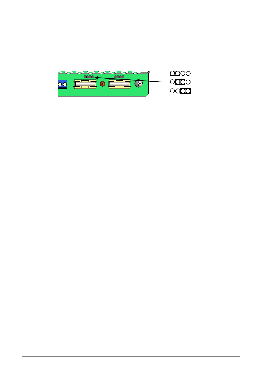
10) Select the Battery type by placing the link (above the Battery fuse) in the appropriate location to
select (17/18 Ah, 38 Ah [Factory set] or 65 Ah) batteries. This changes the maximum bulk charge
current, and therefore enables higher load current to be used when smaller batteries are required.
Put the link on the left hand two pins for 17 Ah, the middle pins for 38 Ah and the right hand two
pins for 65 Ah batteries.
Figure 6 –Standby battery size selection links
11) Mount the appropriate batteries as shown above. Where a dual box solution is used all cabling
between the two boxes should be routed to use separate case entry/exit holes from other cabling
and use suitable bushes to protect the cables.
12) Connect the two 12 V standby batteries in series using the single cable provided. Connect the
negative of one battery to the positive of the other. DO NOT CONNECT the other two battery
terminals to each other.
13) Connect the free Positive and Negative terminals of the batteries to the PCB terminals Batt+ and
Batt - using the cables provided. See Figures 4 & 5.
14) Connect the battery temperature sensor (two white wires) to the PCB terminals TMP Sens. See
Figure 5.
15) If the batteries are housed remotely, replace the battery lead assembly (including battery
temperature sensor) with an extended length assembly, provided with the Battery box (Ensure the
temperature sensor and battery connections are made according to figure 5.
16) Re-apply the mains power and verify that the yellow Fault LED stops flashing after about 20 s
(battery connection detected). Verify that the remote GEN PSU Fault monitor shows a closed
contact.
17) Disconnect the mains power. Verify that the green Mains LED extinguishes and the yellow Fault LED
starts to pulse (indicating that the PSU is running from its standby batteries).
18) If connected, verify that the EPS Fault monitor shows an open contact and the PSU Fault monitor
shows a closed contact.
19) Perform a full functional test of system including full alarm condition. Verify that the standby
batteries can support the system load. Note: ensure batteries have sufficient charge.
Final
20) Reconnect the mains. Verify that the green Mains LED illuminates and the yellow Fault LED
extinguishes.
21) If connected, verify that the EPS Fault monitor shows a closed contact and the GEN PSU Fault
monitor shows a closed contact.
22) Close cover and secure using fastening screws provided.
Tamper Connection
1) Once the enclosure has been fixed to the wall, insert the 3mm x 10mm stud from the “L” shaped
taper bracket to the tamper switch. Offer the M4 x 33mm screw to the 5mm diameter hole to the left-hand
side of the top right hand mounting hole.
2) Once the M4 screw is located in the 5mm hole, continue to tighten the screw until the screw is
secured against the rear wall.
3) Ensure the tamper micro-switch is secured and test to verify correct operation of the tamper contact
for the opening of the lid and removal from the wall.
17/ 18 Ah
38 Ah
65 Ah

8
Doc ID: I200448 - 30th June 2021
OPERATING INSTRUCTIONS
In the event of loss of mains, a battery fault or a GEN fault, the corresponding Fault signal contacts will open.
If the output of the PSU fails, the cause of the failure should be investigated e.g. short circuit load,
connection of a deeply discharged battery. The fault should be rectified before restoring power to the PSU. If
any of the fuses require replacing, ensure the correct fuse rating and type is used.
MAINTENANCE
Maintenance
This unit is intended for use by Service Personnel only. There are NO USER SERVICEABLE parts inside.
There is no regular maintenance required of the PSU other than periodic testing, and replacement of the
standby battery. Reference should be made to the battery manufacturer's documentation to determine
typical/expected battery life with a view to periodic replacement of the battery.
DIAGNOSTICS
Local Diagnostics
Green LED On = Mains Present
Yellow LED Fault Diagnostics according to table:
Yellow LED
(fault)
Green LED
(mains)
Status
OFF
ON
Normal: Battery fully charged
One short flash
every second
ON
Normal: Battery charging but not fully charged
Flashing:
1second On
1 second Off
ON
Fault: Output fuse or battery fuse blown, or
battery missing
OFF
Fault: No mains, output fuse blown
One short flash
every 3 seconds
OFF
Fault: No mains, battery supplying load.
OFF
OFF
Fault: No mains, No output, Batteries
disconnected or completely discharged

9
Doc ID: I200448 - 30th June 2021
COMPLIANCE
This power supply unit meets the essential requirements of the following EU Directives:
DISPOSAL OF PRODUCT AT END OF LIFE
This product falls within the scope of EU Directives 2002/96/EC Waste Electrical and Electronic Equipment
(WEEE) and 2006/66/EC (Battery). At the end of life, the product must be separated from the domestic
waste stream and disposed via an appropriate approved WEEE disposal route in accordance with all national
and local regulations.
Before disposal of the product, any batteries must be removed, and disposed separately via an appropriate
approved battery disposal route in accordance with all national and local regulations. Package used batteries
safely for onward transport to your supplier, collection point or disposal facility.
Caution: Risk of fire or explosion
if bare battery wires are allowed to touch.
See Specification for battery type information. The battery is marked with the crossed out wheelie bin
symbol, which may include lettering to indicate cadmium (Cd), lead (Pb), or mercury (Hg).
For more information see: www.recyclethis.info
The packaging supplied with this product may be recycled.
Please dispose of packaging accordingly.
EMC:
2004/108/EC
Low Voltage:
2006/95/EC
WEEE:
2002/96/EC
RoHS:
2011/65/EU
Table of contents
Other Vanderbilt Power Supply manuals