Vanguard CPW 125-4-S Series User manual

Vanguard 037-08OP-002D-01
Equipment, 2017-12
Inc.
Operation and
Maintenance Manual
Weld-Deck welding package CPW 125-4-S2
/ includes Slewing Canopy (037-08OP-003B)
/ includes Auto Tie-In Crane (037-08OP-004B)
S/NCB50600021 – UP (Weld-Deck)
To be used with Cummins® Operation and Maintenance Manual 4021531

S/N CB50600021 – UP (Weld-deck)
VANGUARD EQUIPMENT, INC.
15627 EAST PINE ST
TULSA, OKLAHOMA
74116, USA
℡/: 918.437.1796

S/N CB50600021 – UP (Weld-deck) i
Table of Contents
FOREWORD....................................................................................................................................................................1
LITERATURE INFORMATION ............................................................................................................................................. 1
MACHINE DESCRIPTION................................................................................................................................................... 1
SAFETY........................................................................................................................................................................... 1
OPERATION..................................................................................................................................................................... 1
MAINTENANCE................................................................................................................................................................ 2
MAINTENANCE INTERVALS.............................................................................................................................................. 2
CALIFORNIA PROPOSITION 65.......................................................................................................................................... 2
CERTIFIED ENGINE MAINTENANCE .................................................................................................................................. 2
SAFETY SECTION.........................................................................................................................................................2
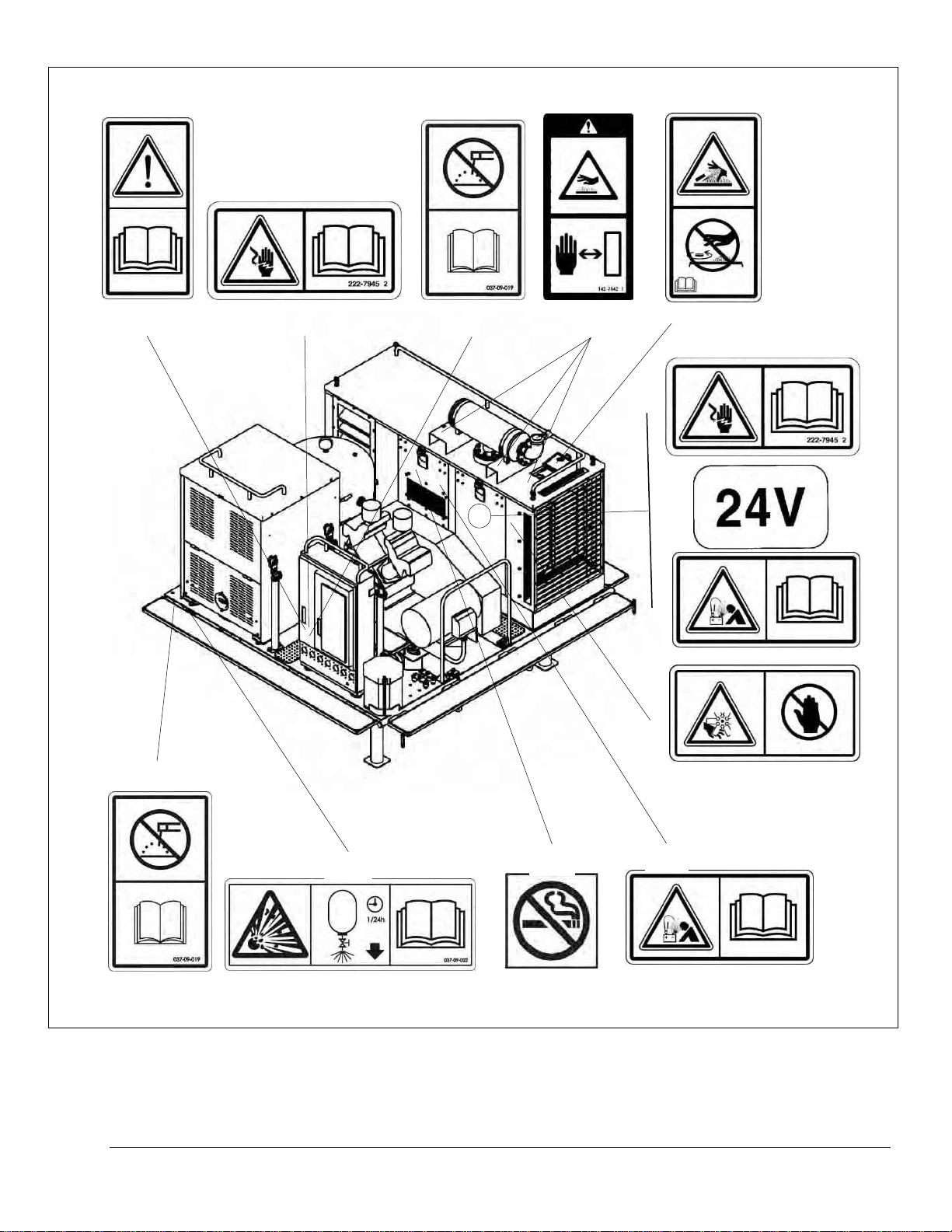
SAFETY SIGNS AND LABELS............................................................................................................................................. 2
Do Not Operate (1)..................................................................................................................................................... 6
Electrical Shock (2) .................................................................................................................................................... 6
Do Not Weld on the Machine (3)................................................................................................................................. 8
Hot Surface (4)........................................................................................................................................................... 9
Hot Fluid Under Pressure (5) ................................................................................................................................... 10
Electrical Shock (6) .................................................................................................................................................. 11
24 Volt DC system (7)............................................................................................................................................... 12
Drain Air Receiver Daily (11)................................................................................................................................... 16
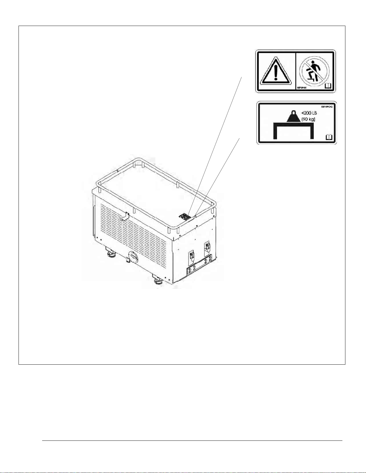
Do Not Step (12)....................................................................................................................................................... 17
Maximum surface load capacity (13)......................................................................................................................... 18
ETHYL ETHER CYLINDER...................................................................................................................................... 19
Batteries................................................................................................................................................................... 20
GENERAL HAZARD INFORMATION.................................................................................................................................. 21
PRESSURE AIR AND WATER............................................................................................................................................ 22
TRAPPED PRESSURE ...................................................................................................................................................... 22
FLUID PENETRATION ..................................................................................................................................................... 22
CONTAINING FLUID SPILLAGE ....................................................................................................................................... 22
INHALATION ................................................................................................................................................................. 23
Exhaust..................................................................................................................................................................... 23
Asbestos Information ................................................................................................................................................ 23
DISPOSE OF WASTE PROPERLY ...................................................................................................................................... 23
CRUSHING PREVENTION AND CUTTING PREVENTION ...................................................................................................... 23
BURN PREVENTION........................................................................................................................................................ 24
Coolant..................................................................................................................................................................... 24
Oils .......................................................................................................................................................................... 24
Batteries................................................................................................................................................................... 24
FIRE PREVENTION AND EXPLOSION PREVENTION............................................................................................................ 24
General.................................................................................................................................................................... 24
Battery and Battery Cables ....................................................................................................................................... 26
Wiring...................................................................................................................................................................... 27
Lines, Tubes and Hoses............................................................................................................................................. 27
Ether........................................................................................................................................................................ 28
Fire Extinguisher...................................................................................................................................................... 28
Fire Safety................................................................................................................................................................ 28
Fire Extinguisher Location ....................................................................................................................................... 29
ELECTRICAL CABLES AND WIRE-HARNESSES................................................................................................................... 29
ELECTRICAL STORM INJURY PREVENTION...................................................................................................................... 29
BEFORE STARTING GENSET-ENGINE .............................................................................................................................. 29
GENSET-ENGINE STARTING........................................................................................................................................... 29
BEFORE OPERATING EQUIPMENT ................................................................................................................................... 30
VISIBILITY INFORMATION.............................................................................................................................................. 30
OPERATION................................................................................................................................................................. 30
MACHINE OPERATING TEMPERATURE RANGE ................................................................................................................ 30
MACHINE OPERATION ................................................................................................................................................... 30
MACHINE PARKING ....................................................................................................................................................... 31
GENSET ENGINE STOPPING ............................................................................................................................................ 31

S/N CB50600021 – UP (Weld-deck) ii
SOUND LEVEL INFORMATION......................................................................................................................................... 31
Sound Level Information for Machines in European Union Countries and in Countries that Adopt the “EU Directives”
................................................................................................................................................................................. 31
VIBRATION ................................................................................................................................................................... 31
GUARDS (OPERATOR PROTECTION)................................................................................................................................ 31
PRODUCT INFORMATION SECTION (CPW-124-4-S2)........................................................................................... 32
GENERAL INFORMATION................................................................................................................................................ 32
Equipment Information Section................................................................................................................................. 32
Restrictions to Application and Configuration........................................................................................................... 35
IDENTIFICATION INFORMATION........................................................................................................................... 35
PLATE LOCATIONS AND FILM LOCATIONS ...................................................................................................................... 35
CE MARK ..................................................................................................................................................................... 35
ISO SYMBOLS (MODEL USAGE)..................................................................................................................................... 36
DECLARATION OF CONFORMITY .................................................................................................................................... 37
EMISSIONS CERTIFICATION FILM ................................................................................................................................... 37
OPERATION SECTION............................................................................................................................................... 39
MOUNTING AND DISMOUNTING ..................................................................................................................................... 39
BATTERY DISCONNECT SWITCH..................................................................................................................................... 40
OPERATOR CONTROLS................................................................................................................................................... 41
Emergency Stop........................................................................................................................................................ 41
Control Panel Illumination Button ............................................................................................................................ 42
Genset Stop/Run/Start Switch.................................................................................................................................... 42
Rated/Idle Switch...................................................................................................................................................... 43
Ether Starting Aid..................................................................................................................................................... 43
Genset Engine Gauges and Indicators....................................................................................................................... 44
Main Supply AC Circuit Breaker............................................................................................................................... 46
Main Supply AC Meters............................................................................................................................................ 47
Three Phase Equipment Circuit Breakers and Receptacles........................................................................................ 49
60Hz Single Phase Front-Mounted Equipment Receptacles and Circuit Breakers with Ground Fault Circuit
Interrupters (GFCI) — Standard Receptacles............................................................................................................ 50
50Hz Single Phase Front-Mounted Equipment Receptacles and Circuit Breakers with Feeder Circuit Ground Fault
Circuit Interrupters (GFCI) — Optional Receptacles................................................................................................. 52
Single Phase Equipment Ground Fault Circuit Interrupters (GFCI)—Connecting To................................................. 53
AIR COMPRESSOR ......................................................................................................................................................... 54
Air Compressor Start/Stop Switch............................................................................................................................. 54
Compressed Air Pressure Gauge............................................................................................................................... 55
Compressed Air Receiver Drain Valve ...................................................................................................................... 56
Compressed Air Supply Line Tee............................................................................................................................... 56
Air Receiver Relief Valve .......................................................................................................................................... 57
Air Compressor and tank .......................................................................................................................................... 57
WELDER DOGHOUSE ENCLOSURE .................................................................................................................................. 58
BEFORE STARTING GENSET-ENGINE .............................................................................................................................. 59
Welding deck............................................................................................................................................................ 59
Welder Doghouse ..................................................................................................................................................... 59
Genset...................................................................................................................................................................... 59
Control/Distribution Center...................................................................................................................................... 60
GENSET COLD WEATHER OPERATION............................................................................................................................ 61
Winter-fronts............................................................................................................................................................ 62
GENSET-ENGINE STARTING........................................................................................................................................... 62
Starting Above 0°C (32°F)........................................................................................................................................ 62
Cold Weather Starting Below 0°C (32°F) with Ether Starting.................................................................................... 63
Genset Engine Starting with Jump Start Cables......................................................................................................... 64
Use of Jump Start Cables.......................................................................................................................................... 64
Starting Procedure After Extended Shutdown or Oil Change ..................................................................................... 65
After Starting the Engine........................................................................................................................................... 65
AC POWER-UP ............................................................................................................................................................. 66
Ground Fault Circuit Interrupters (GFCI) 60 Hz—Test Daily.................................................................................... 67
Ground Fault Circuit Interrupters (GFCI) 50 Hz—Test Daily.................................................................................... 68

S/N CB50600021 – UP (Weld-deck) iii
GENSET SHUTDOWN ...................................................................................................................................................... 70
MACHINE PARKING ....................................................................................................................................................... 71
TRANSPORTATION INFORMATION................................................................................................................................... 71
Shipping the Carrier-Mounted Weld-Deck................................................................................................................. 71
Towing the Carrier................................................................................................................................................... 71
MAINTENANCE SECTION......................................................................................................................................... 73
TORQUE SPECIFICATIONS .............................................................................................................................................. 73
Torques for Standard Fasteners................................................................................................................................ 74
Torques for Metric Fasteners.................................................................................................................................... 74
Torques for Vibration Isolator Mounts...................................................................................................................... 75
Maintenance Welding to the Weld-deck..................................................................................................................... 76
RECOMMENDED SERVICE INTERVALS—MINIMUM SERVICE............................................................................................ 77
Break-in Periods....................................................................................................................................................... 77
10 Hours or Daily..................................................................................................................................................... 77
250 Hours or 3 Months............................................................................................................................................. 78
500 Hours or 6 Months............................................................................................................................................. 78
1000 Hours or Yearly................................................................................................................................................ 79
All Other Service Intervals........................................................................................................................................ 79
GENSET FREQUENCY CONFIGURATION—60HZ AND 50HZ MODES.................................................................................. 79
60Hz Mode............................................................................................................................................................... 80
50Hz Mode............................................................................................................................................................... 82
SINGLE PHASE FRONT-MOUNTED EQUIPMENT RECEPTACLES—INSTALLATION ............................................................... 85
ENGINE LUBRICATING OIL AND FILTER CHANGE............................................................................................................ 87
COOLING SYSTEM:CORE -CLEAN ................................................................................................................................. 89
COOLING SYSTEM:SERVICE .......................................................................................................................................... 90
AIR CLEANER SERVICE.................................................................................................................................................. 90
AIR COMPRESSOR ......................................................................................................................................................... 91
AIR COMPRESSOR MOTOR BEARINGS............................................................................................................................. 91
BOTTLE RACK –GAS BOTTLE CHANGE .......................................................................................................................... 91
TROUBLESHOOTING................................................................................................................................................. 93
GENERAL INFORMATION................................................................................................................................................ 93
ENGINE FAULTS:........................................................................................................................................................... 93
Engine Won’t Crank ................................................................................................................................................. 94
Engine Won’t Start ................................................................................................................................................... 95
Engine Will Not Idle ................................................................................................................................................. 96
Engine Will Not Go to Full Speed (Run).................................................................................................................... 96
Batteries fail to charge (low DC voltage) .................................................................................................................. 97
24VDC Alternator Overcharging (High DC voltage)................................................................................................. 98
NO OR LOW 480 VAC THREE PHASE SUPPLY VOLTAGE ................................................................................................. 99
MAIN BREAKER WILL NOT SET ..................................................................................................................................... 99
120 VAC OR 240 VAC GROUND FAULT INTERRUPTER (GFCI) CIRCUIT BREAKERS WILL NOT SET.................................100
ELECTRICAL SCHEMATICS ............................................................................................................................................101
480VAC, 60 Hz Supply Schematic............................................................................................................................101
24VDC Controls Schematic......................................................................................................................................102
COMPRESSOR FAULTS ..................................................................................................................................................103
APPENDICES: EQUIPMENT MODULES’ OPERATION AND MAINTENANCE MANUALS.............................104
APPENDIX A—AIR CLEANER SERVICE ........................................................................................................................105
APPENDIX B—AIR COMPRESSOR ................................................................................................................................109
APPENDIX C—AC GENERATOR AND VOLTAGE REGULATOR ........................................................................................141
APPENDIX D—ENGINE DIAGNOSTIC TROUBLE CODES .................................................................................................170
APPENDIX E—ENGINE DIGITAL DISPLAY ....................................................................................................................188
APPENDIX F—SLEWING CANOPY.................................................................................................................................225
APPENDIX G—AUTO TIE-IN CRANE.............................................................................................................................299
APPENDIX H—GENSET ENGINE ..................................................................................................................................391

037-08OP-002D-01 S/N CB50600021 – UP (Weld-deck) 1
Foreword
Literature Information
This manual should be stored in the genset compartment's literature holder in the left door (closest to the radiator end).
This manual contains safety information, operation instructions, transportation information, lubrication information and
maintenance information. This manual also contains supplemental operation and maintenance manuals supplied by the
original equipment manufacturers that detail specific procedures that must be followed in addition to the information
outlined in the Weld-Deck Operation and Maintenance Manual, Weld-Deck welding package CPW 125-4-S2.
Some photographs or illustrations in this publication show details or attachments that can be different from your machine.
Guards and covers might have been removed for illustrative purposes.
Continuing improvement and advancement of product design might have caused changes to your machine which are not
included in this publication. The latest version of this publication is available for downloaded from the internet at
http://vanguardequip.com/. Read, study and keep this manual with the machine.
Machine Description
Vanguard’s Continuously Powered Welding (CPW) Package attachment is a modular, self powered design that can be
mounted to a variety of carriers—pipelayers, crawler tractors, etc.—or on a self-contained skid-mount. It provides clean,
stable alternating current (AC) to power a variety of welding power units and auxiliary equipment. The CPW 125-4-S2-s-s2
(or series 2) unit can be configured to provide either 480/120-240VAC at a frequency of 60Hz, or 415/240VAC at a
frequency of 50Hz.
The primary use of this machine is for petroleum-product pipeline construction.
The operator should read, understand, and follow both the carrier’s and the CPW’s operating and maintenance instructions.
The operator must comply with all pipeline-construction procedures, regulations, and safety precautions.
This equipment is to be operated by qualified personnel only.
The daily service/inspection procedure should be performed before start-up.
Note: Refer to the specific module’s—Compressor, Engine, Generator, Welding Power-unit—operation and maintenance
manuals for detailed information on the operation of the respective module.
Safety
The safety sections list basic safety precautions. In addition, these sections identify the text and locations of warning signs
and labels used on the machine.
Read and understand the basic precautions listed in the safety sections before operating or performing lubrication,
maintenance and repair on this machine.
This equipment is to be operated and serviced by qualified personnel only. To become familiar with the basic safety
precautions and warning sign locations and wording, at a minimum they must read and understand the safety section before
operating or performing lubrication, maintenance and repair on this equipment.
Do not attempt to bypass any of the safety equipment or instrumentation on this equipment.
Do not attempt to operate this equipment with any of the safety equipment or instrumentation bypassed.
Certain conditions and precautions are peculiar to pipeline construction operations. The following represents the minimum
considerations for safe operation of this equipment.
Operation
The operation section is a reference for the new operator and a refresher for the experienced operator. This section includes a
discussion of gauges, switches, machine controls, and transportation information.
Photographs and illustrations guide the operator through correct procedures of checking, starting, operating, and stopping
the equipment.
Additional operation and maintenance information for key components such as the genset engine, genset alternator, and air
compressor, etc., are included in the Original Equipment Manufactures' manuals contained in the appendices of this manual.
These Original Equipment Manufactures' manuals should also be read and understood before operating or performing
lubrication, maintenance and repair on this machine

037-08OP-002D-01 S/N CB50600021 – UP (Weld-deck) 2
Maintenance
The maintenance section is provided for quick, general reference only. They do not outline all of the inspection and service
procedures that MUST be performed to the various modules. Refer to the specific module’s—Compressor, Engine,
Generator, etc.—operation and maintenance manuals for complete and detailed information on the care of the respective
module.
The maintenance sections are guides to equipment care. The Maintenance Interval Schedules (MIS) list the items to be
maintained at a specific service interval. Items without specific intervals are listed under the "When Required" service
interval.
Maintenance Intervals
Use the service hour meter to determine servicing intervals. Calendar intervals shown (daily, weekly, monthly, etc.) can be
used instead of service hour meter intervals if they provide more convenient servicing schedules and approximate the
indicated service hour meter reading. Recommended service should always be performed at the interval that occurs first.
Under extremely severe, dusty or wet operating conditions, more frequent lubrication than is specified in the maintenance
intervals charts might be necessary.
Perform service on items at multiples of the original requirement. For example, at every 500 service hours or 3 months, also
service those items listed under every 250 service hours or monthly and every 10 service hours or daily.
California Proposition 65
Diesel engine exhaust and some of its constituents are known to the State of California to cause cancer, birth defects, and
other reproductive harm.
Battery posts, terminals and related accessories contain lead and lead compounds. Wash hands after handling.
Certified Engine Maintenance
Proper maintenance and repair is essential to keep the engine and machine systems operating correctly. As the heavy duty
off-road diesel engine owner, you are responsible for the performance of the required maintenance listed in the Owner
Manual, Operation and Maintenance Manual, and Service Manual.
It is prohibited for any person engaged in the business of repairing, servicing, selling, leasing, or trading engines or
machines to remove, alter, or render inoperative any emission related device or element of design installed on or in an
engine or machine that is in compliance with the regulations (40 CFR Part 89). Certain elements of the machine and engine
such as the exhaust system, fuel system, electrical system, intake air system and cooling system may be emission related and
should not be altered unless approved by Vanguard.
Safety Section
Safety Signs and Labels
There are several specific safety signs on this equipment. The exact location of the hazard and the description are reviewed
in this section. Become familiarized with all safety signs.
Make sure that all of the safety signs are legible. Clean or replace the safety signs if you cannot read the words. Replace the
illustrations if the illustrations are not visible. Use a cloth, water, and mild soap to clean the safety signs. Do not use solvent,
gasoline, or other harsh chemicals to clean the safety signs. Solvents, gasoline, or harsh chemicals could loosen the adhesive
that secures the safety message. Loose adhesive will allow the safety message to fall.
Do not use pressure washers to clean the safety signs.
Replace any safety sign that is damaged, or missing. If a safety sign is attached to a part that is replaced, install a safety sign
on the replacement part. Vanguard Equipment can provide new safety signs.

037-08OP-002D-01 S/N CB50600021 – UP (Weld-deck) 3
1234
6
7
8
5
3
11 10 8
9

037-08OP-002D-01 S/N CB50600021 – UP (Weld-deck) 4
3
6
10
10
6
2
9
9
13 12

037-08OP-002D-01 S/N CB50600021 – UP (Weld-deck) 5
12
13
The optional 4x1 welder enclosure replaces the 2x2
welder enclosure on the welddeck (the relative locations
of 12 & 13 are shown on the previous page).

037-08OP-002D-01 S/N CB50600021 – UP (Weld-deck) 6
Do Not Operate (1)
WARNING! Do not operate or work on this machine unless you have read and understand the instructions and
warnings in the Operation and Maintenance Manuals. Failure to follow the instructions or heed the warnings could
result in injury or death. Contact your dealer for replacement manuals. Proper care is your responsibility.
Safety message (1) is located on main door of the control/distribution center.
Figure 1: Do not operate (1)
Electrical Shock (2)
WARNING! Shock/Electrocution Hazard! Read and understand the instructions and warnings in the Operation and
Maintenance Manual. Failure to follow the instructions or heed the warnings could cause serious injury or death.
High voltage poses an electrocution hazard; this equipment must be operated by qualified personnel only.
DO NOT OPEN the inner main panel door unless you are a qualified service technician, and are familiar with the
dangers of high voltage. DO NOT REMOVE the rear access cover unless you are a qualified service technician, and
are familiar with the dangers of high voltage. The main electrical lines coming into the bottom of the main supply AC
circuit breaker (CB1) from the genset are LIVE, and HIGH VOLTAGE is present on the main incoming lines
WHENEVER the genset is running, EVEN WHEN THE MAIN CIRCUIT BREAKER (CB1) IS DE-ENERGIZED
(O).
037-05-63-307A

037-08OP-002D-01 S/N CB50600021 – UP (Weld-deck) 7
Safety message (2) is located on outer main door, and on the inner main panel door of the control/distribution center. Safety
message (2) is also located on the rear access panel on the control/distribution center.
Figure 2: Electrical Shock (2)
037-05-63-307A
037-05-63-313A
037-05-63-311B

037-08OP-002D-01 S/N CB50600021 – UP (Weld-deck) 8
Do Not Weld on the Machine (3) Notice
Do not weld on, or modify this machine unless you have read and understand the instructions and warnings in the Operation
and Maintenance Manuals. Improper welding or modifications to this machine could seriously damage the Genset Engine.
See the Maintenance Welding to the Weld-deck section in the Operation and Maintenance Manual.
Information message (3) is located on main door of the control/distribution center. Message (3) is also located on the Genset
Enclosure Door. Message (3) is also located at the front of the Weld-Deck, under the Access-ways.
Figure 3: Do Not Weld on the Machine (3)
037-05-63-307A
037-05-09-300B 037-05-09-301A

037-08OP-002D-01 S/N CB50600021 – UP (Weld-deck) 9
Hot Surface (4)
WARNING! Hot parts or hot components can cause burns or personal injury. Do not allow hot parts or components
to contact your skin. Use protective clothing or protective equipment to protect your skin. Keep away from hot
surfaces.
Safety message (4) is located on top of the Genset Enclosure close to exhaust muffler (three places).
Figure 4: Hot Surface (4)
037-05-05-111A
037-09-50-026A

037-08OP-002D-01 S/N CB50600021 – UP (Weld-deck) 10
Hot Fluid Under Pressure (5)
WARNING! Pressurized system! Hot coolant can cause serious burns, injury or death. To open the cooling system
filler cap, stop the engine and wait until the cooling system components are cool. Loosen the cooling system pressure
cap slowly in order to relieve the pressure. Read and understand the Operation and Maintenance Manual before
performing any cooling system maintenance.
Safety message (5) is located beside the radiator fill opening, on top of the Genset Enclosure.
Figure 5: Hot Fluid Under Pressure (5)
037-05-05-111A
037-09-50-305A

037-08OP-002D-01 S/N CB50600021 – UP (Weld-deck) 11
Electrical Shock (6)
WARNING! Shock/Electrocution Hazard! Read and understand the instructions and warnings in the Operation and
Maintenance Manual. Failure to follow the instructions or heed the warnings could cause serious injury or death.
Safety message (6) is located on the Genset Enclosure service door. Message (6) is also located on the Genset Enclosure
service panel, and on the generator electrical connection box inside of the Genset Enclosure.
Figure 6 Electrical Shock (6)
037-09-50-302A
037-05-09-300B
(6) (6)
037-09-011

037-08OP-002D-01 S/N CB50600021 – UP (Weld-deck) 12
24 Volt DC system (7) Notice
The Genset Engine operates on a 24Volt DC electric system. This includes the batteries, charging, starter-motor, and control
system. Do not attempt to connect to another system that operates on a different voltage than 24 Volts DC. Read and
understand the instructions and warnings in the Operation and Maintenance Manual. Failure to follow the instructions or
heed the warnings could cause serious injury, or could seriously damage the Genset Engine.
Information message (7) is located on the Genset Enclosure service panel, battery/charging system access.
Figure 7: 24 Volt DC system (7)
037-05-05-111A
037-09-50-302A

037-08OP-002D-01 S/N CB50600021 – UP (Weld-deck) 13
Improper Connections for Jump Start Cables (8)
Warning! Explosion Hazard! Improper jumper cable connections can cause an explosion resulting in serious injury
or death. Batteries may be located in separate compartments. Refer to the Operation and Maintenance Manual for
the correct jump starting procedure.
Safety message (8) is located on the Genset Enclosure service panel, battery/charging system access. Message (8) is also
located inside the enclosure on the Genset Engine air filter, above the batteries
Figure 8: Improper Connections for Jump Start Cables (8)
037-05-05-111A
037-09-50-302A
(8)
037-09-011

037-08OP-002D-01 S/N CB50600021 – UP (Weld-deck) 14
Fan Do Not Touch (9)
Warning! Rotating Fan, do not touch. Serious injury can occur if body parts come into contact with the rotating fan.
Keep body parts, and loose clothing away from the rotating fan at all times. Keep objects away from moving fan
blades. The fan blades will throw objects or cut objects.
Safety message (9) is located inside the Genset Enclosure on both sides of the Radiator Fan Guard. Message (9) is also
located at the top and on the side near the Fan Guard around the Generator.
Figure 9: Fan Do Not Touch (9)
037-09-50-302A 037-09-50-303A
(9)
037-09-011
(9)

037-08OP-002D-01 S/N CB50600021 – UP (Weld-deck) 15
Do Not Smoke (10)
Warning! Explosion Hazard! Do Not Smoke inside the Genset Enclosure. Ether cylinder present, do not smoke inside
the genset compartment. Do not smoke while changing ether cylinders.
Safety message (10) is located inside the Genset Enclosure on both sides of the Engine.
Figure 10: Do Not Smoke (10)
(10)
037-09-011
(10)
037-05-09-002
(10)
037-09-011
This manual suits for next models
5
Table of contents
Popular Welding System manuals by other brands

EWM
EWM Taurus 400 Basic TDG operating instructions

Lincoln Electric
Lincoln Electric Red-D-Arc EX350i Operator's manual

Miller Electric
Miller Electric MILLERMATIC 35 owner's manual

GYS
GYS TITANIUM 400 AC/DC manual

Mosa
Mosa MAGIC WELD 200 YD Use and maintenance manual

CIGWELD
CIGWELD weldskill 100 operating manual

Lincoln Electric
Lincoln Electric BESTER Magster 401 operating manual

Blue Demon
Blue Demon IGBT Series owner's manual

Kemppi
Kemppi KEMPACT 251R quick guide

EWM
EWM Taurus 301 Synergic operating instructions

Hobart Welding Products
Hobart Welding Products IronMan 275 owner's manual

Miller
Miller SQUAREWAVE 1000 owner's manual