Vannus Luna-5B/36 LED User manual

Luna-5B/36 LED
Luna-5B/40 LED
Luna-5B/46 LED
Luna-5B/56 LED
INSTRUCTION MANUAL

Warning
Installation and maintenance work shall only be performed by qualified persons, familiar
with local code and regulation, and experienced with this type of appliance.
All field wiring must be installed in accordance with the national wiring regulation.
Ensure that the rated voltage of the unit corresponds to that of the name plate before
commencing wiring work according to the wiring diagram.
The unit must be GROUNDED to prevent possible hazard due to insulation failure.
The earth wire is approximately 60mm longer than safety wire. This is to ensure at the
event whereby the suspension system fails, the (L) and (N) wire will break leaving the
fan remain earthed to prevent electrocution.
Tighten the blade firmly using a screw driver.
Blades that are detached from the unit during operation will cause serious injuries and
property damages.
This appliance is not intended for use by persons (including children) with reduced
physical, sensory or mental capabilities, or lack of experience and knowledge, unless
they have been given supervision or instruction concerning use of the appliance by a
person responsible for their safety.
Children should be supervised to ensure that they do not play with the appliances.
Confirm that the power supply has been switched OFF before installing or servicing the
unit. Ensure that the blade is fully static before doing any maintenance work.
Safety Precaution
1. Safety Precaution ................................................................................. 1 - 2
2. Parts & Accessories .............................................................................. 3
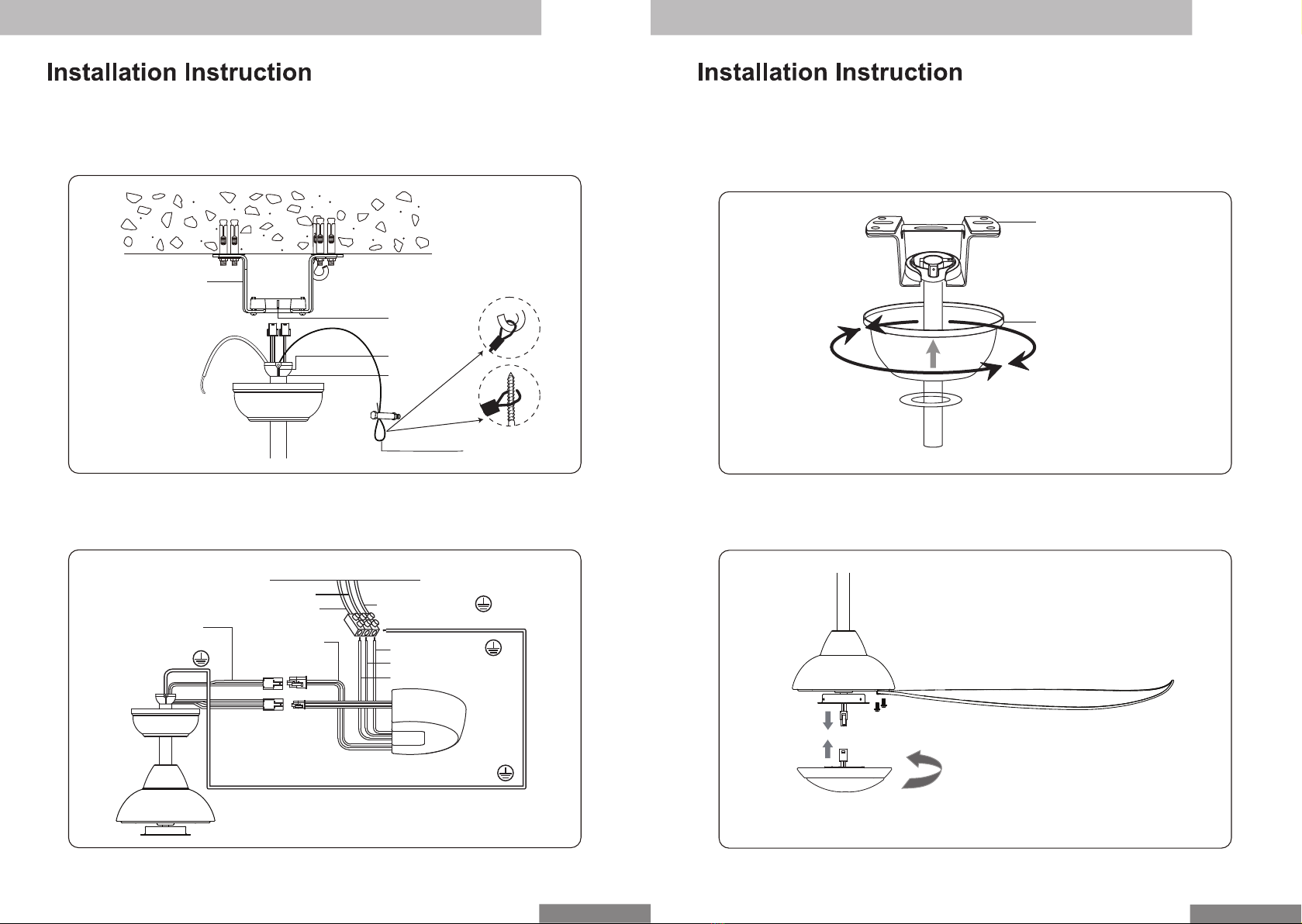
3. Installation Instruction ........................................................................... 4 - 7
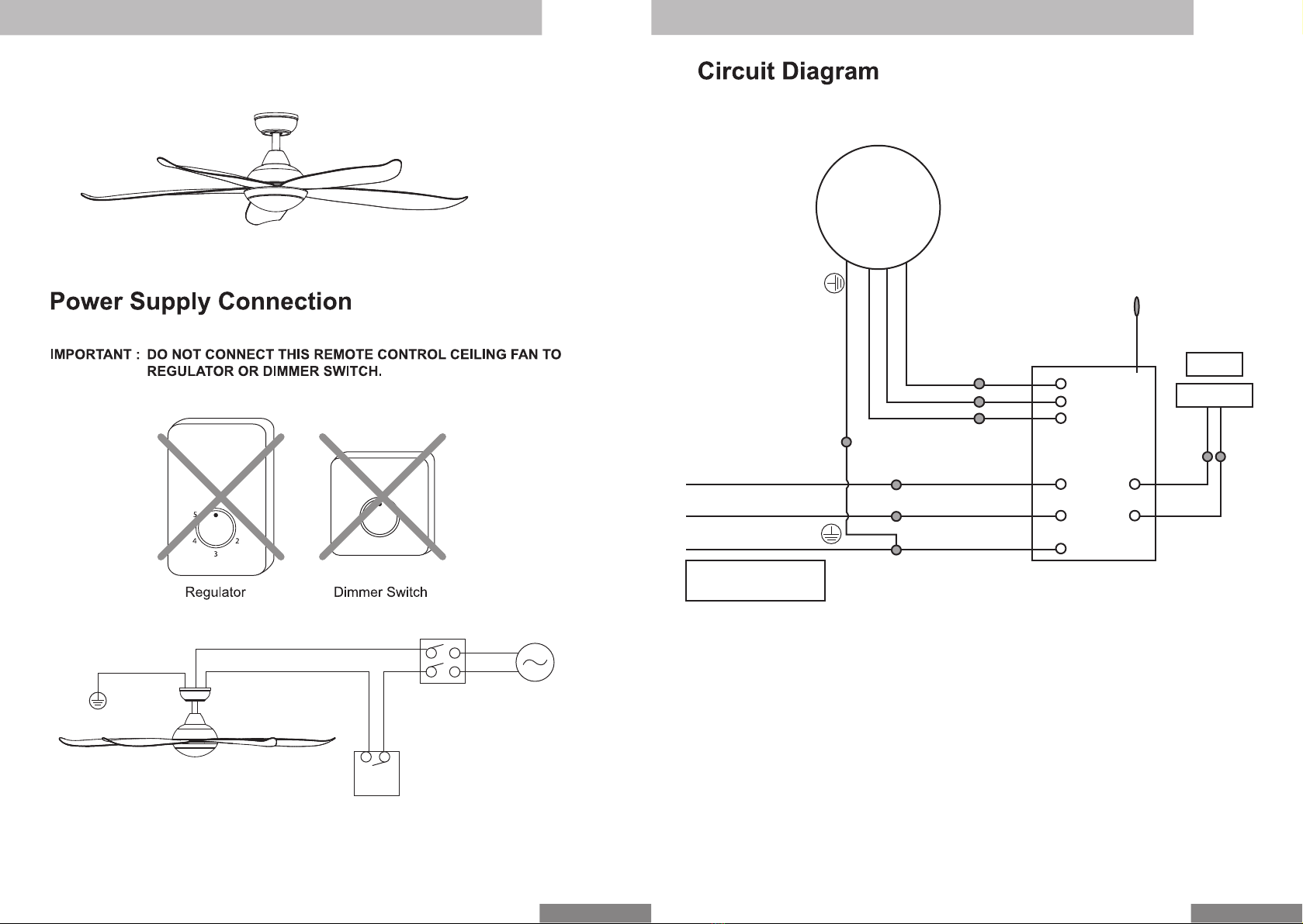
4. Power Supply Connection .................................................................... 7
5. Circuit Diagram ..................................................................................... 8
6. Transmitter Programming ..................................................................... 9
7. Transmitter Function & Assembly ......................................................... 10
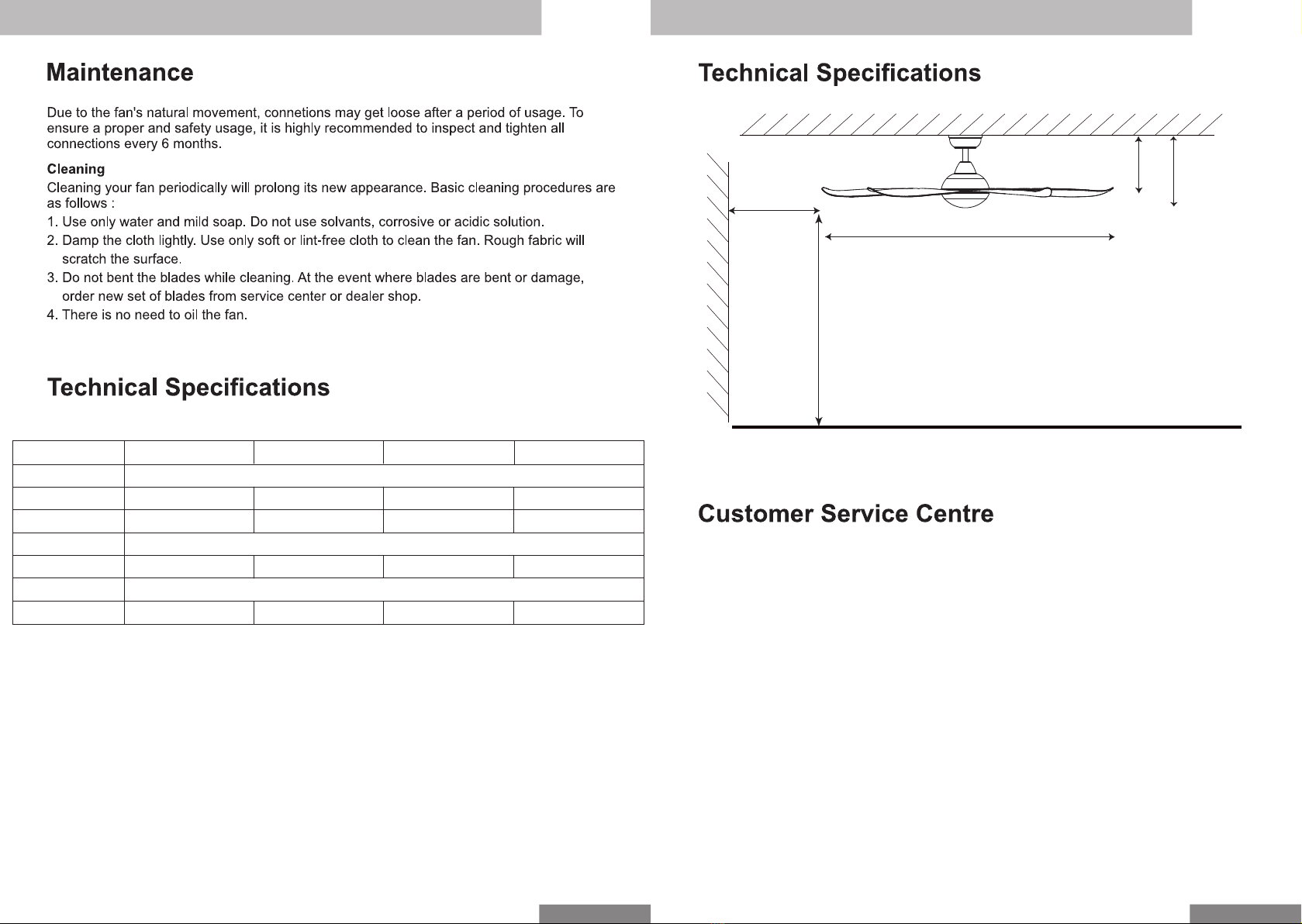
8. Maintenance ........................................................................................ 11
9. Technical Specifications ....................................................................... 11 - 12
10. Customer Service Centre ................................................................... 12
STOP using the ceiling fan when any abnormality or failure occurs.
If unusual oscillating movement is observed, immediately stop using the ceiling fan and
contact the manufacturer, its service agent or suitably qualified persons.
CAUTION
Please take note of the following important points when installing.
The fixing means for attachment to the ceiling such as hooks or other devices shall be
fixed with a sufficient strength to withstand 4 times the weight of the ceiling fan.
The mounting of the suspension system shall be performed by the manufacturer, its
service agent or suitably qualified persons.
The fan is to be installed so that the blades are more than 2.5m above the floor.
Safety cord should not be longer than the earthing conductor.
Should failure of the suspension system occur, the supporting of the fan must not rely on
the earthing conductor. The earthing terminal in the fan assembly should be such that
should any part of the suspension system fall off, the body of the fan assembly shall
effectively earthed.
Ensure that the unit’s panel is closed after service or installation.
Unsecured panels will cause the unit to operate noisily.
Sharp edges and coil surfaces are potential locations which may cause injury
hazards. Avoid from being in contact with these places.
Before turning off the power supply set the remote controller’s ON/OFF switch to
the “OFF” position.
If this is not done, the unit’s fans will start turning automatically when power resumes,
posing a hazard to service personnel or the user.
Do not operate any heating apparatus too close to the ceiling fan unit or use in room
where mineral oil, oil vapour or oil steam exist, this may cause plastic part to melt or
deform as a result of excessive heat or chemical reaction.
Ensure the colour of wires of the outdoor unit and the terminal markings are same to the
indoors respectively.
Don’t use joined and twisted wires for incoming power supply.
Do not place any object in the path of the blades. Avoid raising objects or your arms near
the ceiling fan.
The fan suspension system and blade screw tightening shall be examined yearly.
Replacement of parts of the safety suspension system device shall be performed by the
manufacturer, its service agent or suitably qualified persons.
Safety Precaution
2
Torque value for screw/bolts for securing primary suspension system for motor is 2Nm.
The appliance must be permanently connected to the electricity supply through a double
pole switch having a contact separation of at least 3mm in all poles.

3
34
Motor Assembly with Downrod
and Coupling Cover
LED Light Kit
Blade x 5
Blade Screw x 11
Battery x 2
Transmitter &
Holder x 1
Wall Screw x 2
3H
1H 6H
1
2
3
4
6
5
OFF
Expansion Screw x 4 Expansion ‘J’ x 1
Notch Ball x 1
Wooden Screw x 4
Mounting Bracket Receiver
AAA
AAA
Step 1 - Notch Ball, Canopy and Coupling Cover is pre-assrmbled to Motor in packaging.
IMPORTANT : THE EXPANSION SCREWS, EXPANSION ‘J’ HOOK AND NUT MUST
BE TIGHTENED UNTIL SNUG.
Step 2 - Drill the 4 Expansion Screws and 1 Expansion ‘J’ Hook provided to the concrete
ceiling. Align the slotted holes in the mounting bracket with the expansion screws and
secure with the washer and nuts
Expansion ‘J’ Hook
Expansion Screw
Mounting Bracket
Nut
Insulating sleeveCurrent carrying wires
Locking pin
Cross bolt
Locking nut Motor shaft
Insulating
sleeve Safety cord
Earth wire
The diagram below shows the assembly of wires
through downrod
Canopy & Canopy
Cover

56
Led Light Kit
Step 3 - Raise the fan and place the ball into the Mounting Bracket. Align the notch on the
Notch Ball with the indent in the mounting bracket until you hear the notch pop into place.
Hook the Safety Wire onto the expension ‘J’ hook.
Step 4 - Connect the Connectors from Fan and Receiver. Connect the wires from the
Receiver to House’s Supply Wire. Connect Earth Wire to House Supply Earth Terminal.
Indent
Notch
Notch
Ball
Mounting Bracket
Safety Wire
Green/Yellow(E)
Brown (L)
Blue (N)
White
Yellow
Grey
House Supply Wires
Brown (L)
Blue (N) Green/Yellow (E)
White
Yellow
Grey
Green/Yellow (E)
Orange
Blue Orange
Blue
Step 5 - Loosen (do not remove) the two screws on Mounting Bracket. Slide the Canopy
up to Mounting Bracket and place the key hole on the Canopy over the screw on the
Mounting Bracket, turn Canopy until it locks in place at the narrow section of the key holes.
Align the holes on the Canopy with Mounting Bracket and secure with the two set of screws
until snug.
Mounting Bracket
Canopy
Step 6 - Install the Blades on Motor with Screw. Connect the connectors and install
the LED light kit by twisting in.

Below shows a complete installation diagram.
7 8
DC
Motor
ANT
W
N LED+
Blue
Grey
Yellow
White
Neutral (Blue)
Live (Brown)
Earth (Green/Yellow)
Brown
Green/Yellow
MAIN PCB
LED-
L
E
V
U
Power Supply
220V-240V - 50Hz
LED
25W
Orange
Orange
Blue
Blue
Double Pole
Switch
Single Pole
Switch
Power
Supply

9
The receiver & transmitter is pre-programmed in factory. If you wish to control 2 or more
fans using 1 transmitter, the below steps are required.
DO NOT PRESS ANY OTHER BUTTON DURING THIS PROCESS
Step 1
a) Insert the 2 pcs of batteries (provided) into transmitter.
b) Turn on the power supply (wall switch) to the fan.
c) Within 30 sec, press and hold the “OFF” button for 3 sec. Once the receiver has
detected the frequency, transmitter will “Beep Beep” twice. Programming process is
completed and fan is ready to use.
If the fan is not responding to the transmitter, repeat Step 1b.
Press and hold
for 3 sec
Transmitter Learning Process
3H
1H 6H
1
2
3
4
6
5
OFF
10
Transmitter Function
The transmitter & receiver is incorporated with last memory function. This function
stores your last setting in memory and the next time you turn on the fan, fan will
operate as the last setting.
Function of Forward & Reverse
Fan must be turned on and rotating.
Press F/R button and fan will slow down and then change direction (approx. 15 sec).
When the fan is slowing down to change direction, the Fan Speed function is disabled
until direction has been changed.
Forward
Fan rotates anti-clockwise blowing
the air downwards creating the
wind chill effect. Suitable for hot
Reverse
Fan rotates clockwise drawing the air
towards the ceiling circulating the warm
air downwards. This function works best
at low speed. Suitable for air-conditioned
condition.
Mount the remote control
holder on the wall with the
screws provided.
OFF
1 - 6
1H
3H
6H
- Light on/off & select LED colour
- Turn off fan
- Fan speed lowest to highest
- Natural wind, creating gentle sea-
breeze effect
- Foward/Reverse, turn anti-clockwise
or clockwise rotation.
- Timer on - fan turns on after 1hr
- Timer on - fan turns on after 3hr
- Timer on - fan turns on after 6hr
3H
1H 6H
1
2
3
4
6
5
OFF

11 12
More than 1m
More than 2.5m (8’ 2”)
Luna-5B/36 LED: 914mm (3’)
Luna-5B/40 LED: 1015mm (40”)
Luna-5B/46 LED: 1165mm (46”)
Luna-5B/56 LED: 1420mm (56”)
If you need any technical assistance or faulty report, please contact our customer
service centre at :
Alpha Sales & Services Pte. Ltd. (200709461 R)
50, Ubi Avenue 3, #02-16/17, Frontier, Singapore 408866.
Tel : +65 6841 0111 Fax : +65 6747 0030
226mm (8”)
324mm (1’ 1”)
Model
No. of Blades
Fan Width
Motor R.P.M
Voltage
Motor Wattage
LED Wattage
Nett Weight
Luna-5B/40 LED
1015mm (40”)
120 - 275
5W - 35W
5.3kg
Luna-5B/46 LED
1165mm (46”)
90 - 250
5W - 35W
5.9kg
Luna-5B/56 LED
1420mm (56”)
78 - 205
5W - 40W
6.6kg
220V-240V~ 50Hz
25W
Luna-5B/36 LED
914mm (36”)
90 - 255
5W - 35W
5.2kg
5
This manual suits for next models
3
Table of contents
Other Vannus Fan manuals

Vannus
Vannus IRIZ-5B/56 LED User manual

Vannus
Vannus VC2-3B/52 User manual

Vannus
Vannus KS1-3B/56 User manual

Vannus
Vannus VC3-3B/52 LED User manual

Vannus
Vannus FC-AA02/A User manual

Vannus
Vannus Luna-3B/56 User manual

Vannus
Vannus Luna-5B/36 LED User manual

Vannus
Vannus i6-5B/40 User manual

Vannus
Vannus Luna-5B/40 LED User manual
Popular Fan manuals by other brands

IRIS
IRIS WOOZOO PCF-SC15T manual

Windmere
Windmere FN500 Use and care book

kuzco lighting
kuzco lighting FREMONT instruction sheet

Addvent
Addvent Elegance AVX100 operating instructions

Evo
Evo VentCore 10-0800-VCMV Operator's manual

Accurex
Accurex XUEF 100 Series Installation, operation and maintenance manual