manuals.online logo
Brands
  1. Home
  2. •
  3. Brands
  4. •
  5. Vantage Hearth
  6. •
  7. Relay
  8. •
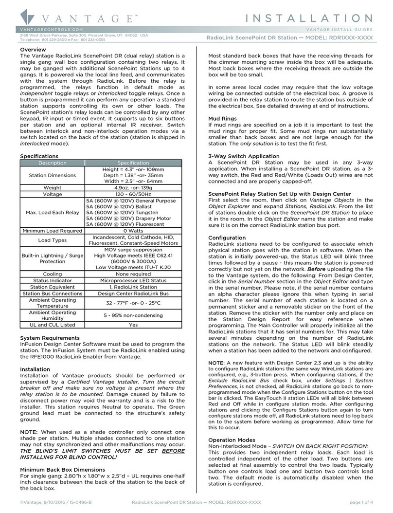
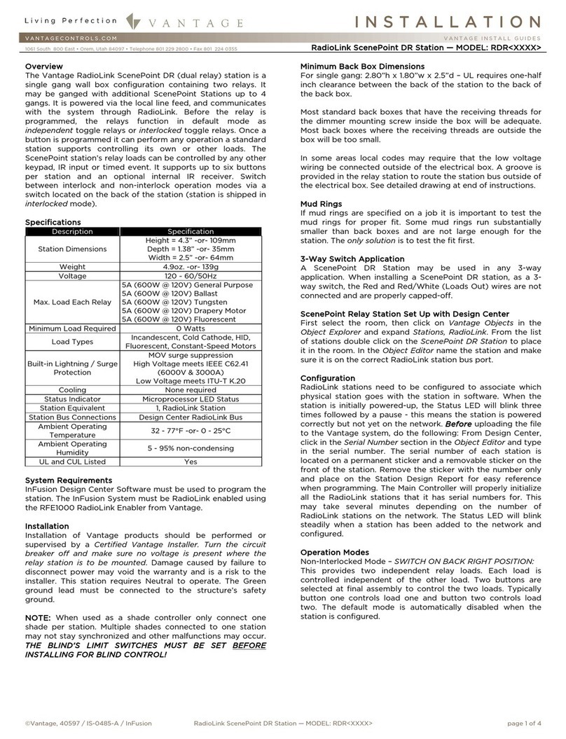
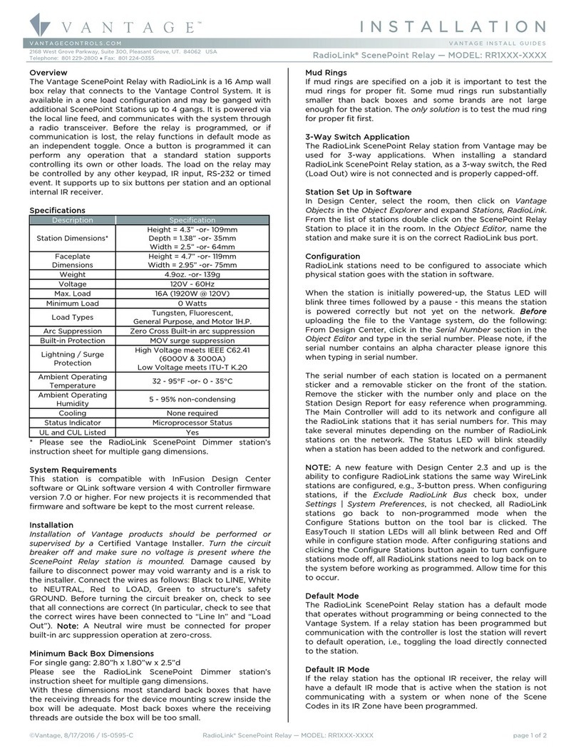
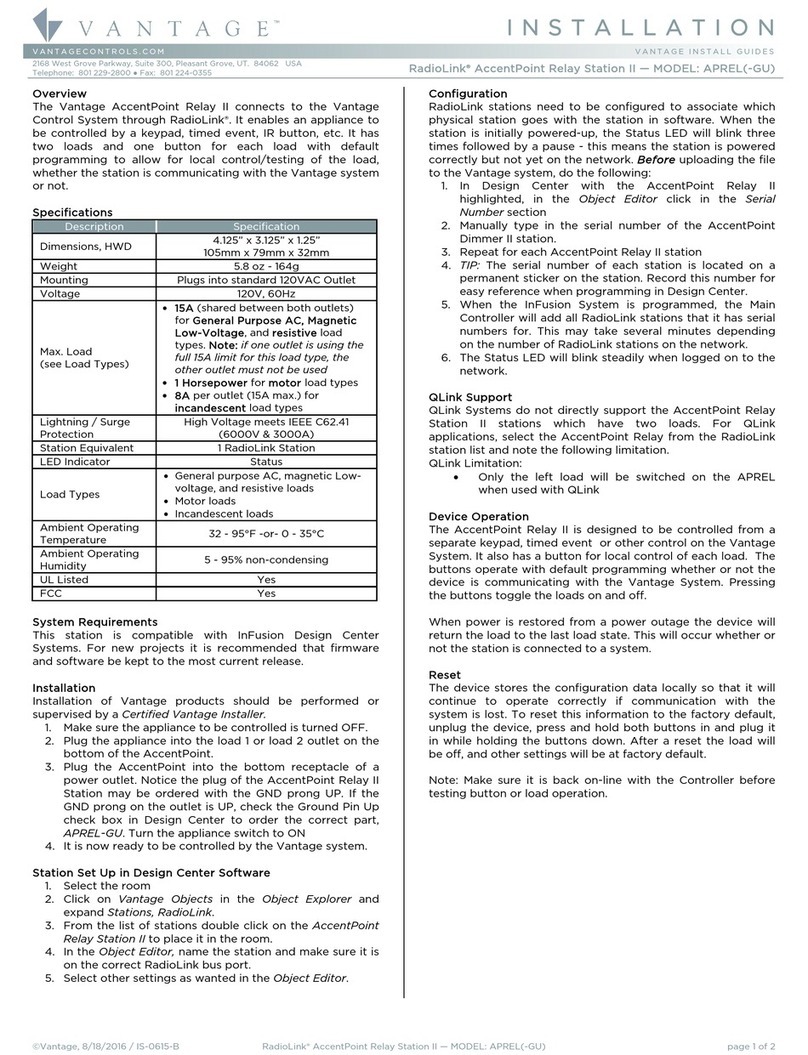
  9. Vantage Hearth WireLink EasyTouch II ScenePoint SR1 Series User manual

Vantage Hearth WireLink EasyTouch II ScenePoint SR1 Series User manual

©Vantage, 8/5/2016 / IS-0473-B WireLink EasyTouch II ScenePoint Relay — MODEL: SR1XX-XXXX page 1 of 4
INSTALLATION
VANTAGECONTROLS.COM VANTAGE INSTALL GUIDES
2168 West Grove Parkway, Suite 300, Pleasant Grove, UT. 84062 USA
Telephone: 801 229-2800 ●Fax: 801 224-0355 WireLink EasyTouch II ScenePoint Relay — MODEL: SR1XX-XXXX
Overview
EasyTouch II ScenePoint Relay is a single gang wall box station
and communicates to the Vantage Control System through the
standard station bus. The station is powered via the local line
feed. Before the station is programmed, or if communication is
lost, the station functions in default mode as an independent
relay. Once the station is programmed, buttons can perform
any operation that a standard station supports. The station’s
load may be controlled by any other keypad, IR input, RS-232,
timed event, etc. The EasyTouch II relay station is available in
one*through five button configurations, single gang. Stations
may be ganged together in any combination up to 4-gangs.
The EasyTouch II Scene-Point relay
station joins Vantage’s premiere line
of backlit stations. An EasyTouch II
can replace a conventional toggle
switch with a stylish, programmable
station. Each button is evenly backlit
with a built in diffuser and three color
LED providing an array of color
choices**, lighting only the lettering on each button. The
backlit lettering color also indicates the button’s status.
Programming provides the user with the option to personalize
the color for ON and OFF status. Additional custom status
colors may be programmed as desired. The EasyTouch II also
features an ambient light sensor for automatic day/night
backlight intensity control* and a built-in IR receiver. See
Design Center software for EasyTouch II ScenePoint faceplate
and button finishes.
*NOTE: A one button station WILL NOT SUPPORT the built-in
ambient light sensor or the IR sensor. When using the Auto
Backlight feature, create a second EasyTouch II keypad style –
one with the Auto Backlight feature unchecked for 1-button
keypads and another with the Auto Backlight feature checked
for multi-button keypads.
**Notes to Installer
EasyTouch II LEDs
Current technology does not allow LED suppliers to guarantee
color values. It is common to have a slight difference among
LEDs, however, this is not too noticeable with backlit
engraving. Historically, blue and red LEDs are more consistent
than green LEDs. Because of this slight variation it is
recommended that one or two stations be pre-programmed
with the colors the client is requesting and shown to the client
for their final approval before ordering and installing.
EasyTouch II Auto Backlight
Issue:
The Auto Backlight feature for EasyTouch II will not change all
stations at the same time.
Description:
EasyTouch II incorporate a built-in light sensor. When enabled
through Vantage software the sensor will change the
brightness of the button LEDs. For example, in normal light the
buttons would be bright. In extremely low light conditions, as
at night time with all the lights off, the buttons would be
dimmed to a very low level. Many conditions lend to the
phenomenon of keypads not changing at the same time. The
location of each keypad is primary. In multiple gang situations
more light may be on one part of the multi-ganged station
causing the auto backlight feature to operate differently in that
section of the multi-gang. Many other lighting factors, even
less noticeable to the human eye, can affect, auto backlight
sensors, intended results.
Solution:
Because manufacture variations are inherent in light sensors
and the conditions mentioned above are inevitable, it is not
always practical to use the Auto Backlight feature. This feature
may be turned off in Software. If the Auto Backlight feature is
not working as the client and installer intends, Vantage
Controls recommends using one of the following two
suggestions to control the brightness of EasyTouch II buttons.
1. Edit the LED style for EasyTouch II buttons by creating two
Modes*. Each mode can use the same ON/OFF colors at
very different intensities. Create two Time Controls. One for
Sunrise and one for Sunset. Program the time controls to
assign the appropriate Mode.
-OR-
2. Create the two Mode LED style as described in step one.
Install a Vantage light sensor and program the light sensor
to change the modes of all the EasyTouch II stations at
once in an area.
Specifications
Description Specification
Station Dimensions
Height = 4.3” -or- 109mm
Depth = 1.38” -or- 35mm
Width = 2.5” -or- 64mm
Weight 5.1oz. / 145g
Voltage 120/240VAC ~ 60/50Hz
Max. Load
16A (1920W @ 120V)
- or -
16A (3840W @ 240V)
Minimum Load
Required 0 Watts
Load Types Incandescent, Cold Cathode, HID,
Fluorescent, Constant-Speed Motors
Arc Suppression Zero Cross Built-in arc suppression
Built-in Lightning /
Surge Protection
MOV surge suppression
High Voltage meets IEEE C62.41 (6000V
& 3000A)
Low Voltage meets ITU-T K.20
Cooling None required
Backlit Buttons 3 color LEDs
Auto LED Intensity Yes, Built-in/standard
IR Receiver Yes, Built-in/standard
Status Indicator Microprocessor Status LED
Station Bus
connections 24V / 36V Station Bus
Station Bus
Specification
2C, 16AWG / 1.31mm2, twisted, non-
shielded, <30pF per foot. Separate a
minimum of 12" / 30.5cm from other
parallel communication and/or high
voltage runs.
Station Equivalent 0.36W on IC-24 / 0.54W on IC-36
Station Wiring
configuration Daisy-chain/Star/Branch
Ambient Operating
Temperature 32 - 95°F -or- 0 - 35°C
Ambient Operating
Humidity 5 - 95% non-condensing
UL and CUL Listed Yes
System Requirements
This station is compatible with InFusion Design Center
software. For complete support it is recommended that
firmware and software be kept to the most current release.
Installation
Installation of Vantage products should be
performed or supervised by a Certified Vantage
Installer. Turn the circuit breaker off and make sure
no voltage is present where the relay station is to be mounted.
Damage caused by failure to disconnect power may void the
warranty and is a risk to the installer. The relay station requires
Neutral to operate. The Green ground lead must be connected
to the structure’s safety ground. A standard station pigtail will
I N S T A L L A T I O N
©Vantage, 8/5/2016 / IS-0473-B WireLink EasyTouch II ScenePoint Relay — MODEL: SR1XX-XXXX page 2 of 4
mate with the station bus connector on the relay station. The
station’s bus wire and Vantage’s pigtail are both rated at
600Volts. A pigtail connects to the station bus using wire nuts,
insulation displacement crimps or any other suitable wire
fastener.
Minimum Back Box Dimensions
Number of Gangs Minimum Back Box Dimensions
1 2.80”h x 1.80”w x 2.5”d
2* 2.80”h x 3.60”w x 2.5”d
3* 2.80”h x 5.40”w x 2.5”d
4* 2.80”h x 7.20”w x 2.5”d
* ScenePoint relay stations are available in one load models
only. 2, 3 and 4 gang Back Box dimensions are calculated by
ganging single load stations together.
NOTE: UL requires one-half inch clearance between the back
of the station to the back of the back box.
Most standard back boxes that have the receiving threads for
the dimmer mounting screw inside the box will be adequate.
Most back boxes where the receiving threads are outside the
box will be too small.
In some areas local codes may require that the low voltage
wiring be connected outside of the electrical box. A groove is
provided in the relay station to route the station bus outside of
the electrical box. See detailed drawing at end of instructions.
Mud Rings
If mud rings are specified on a job it is important to test the
mud rings for proper fit. Some mud rings run substantially
smaller than back boxes and some brands are not large
enough for the station. The only solution is to test the fit first.
3-Way Switch Application
A standard ScenePoint Relay Station may be used in any 3-
way application. When installing a standard ScenePoint Relay
station, as a 3-way switch, the Red (Load Out) wire is not
connected and is properly capped.
Station Setup in Software
InFusion: In the Project Explorer click on Style/Profile View.
Right click on Keypad Styles and select Add Keypad Style. In
the Object Editor window fill in all the information for the
keypad style including the EasyTouch II Button Shape. Select
SoftLine or TrimLine plastic for ScenePoint stations.
Remember to check or uncheck the Auto Backlight check box
to enable or disable this built-in feature. Right click on button
style and setup a button style with the button color wanted.
While still in Style/Profile View, right click on LED Styles and
fill in the appropriate information in the Object Editor for
EasyTouch II LEDs – Red/Green/Blue with ON and OFF colors.
Next select the room, then click on Vantage Objects in the
Object Explorer and expand Stations, WireLink. From the list of
stations double click on the ScenePoint Relay Station to place
it in the room. In the Object Editor, name the station and make
sure it is on the correct WireLink bus.
Configuration
When the station is first connected to the Station Bus, the
diagnostic LED will blink twice followed by a pause, meaning
that the station is connected and powered correctly, but not
configured. In Design Center, click on the Configure Stations
button on the toolbar and highlight the ScenePoint Relay
station. The Status LED will blink 5 times followed by a pause
and the button LEDs will blink rapidly between red and off
indicating that the station is in configuration mode. To finish
configuring press any button on the Station 3 times. The
station may also be configured by typing the serial number in
the project file. Using this method the station will automatically
be configured when the system is programmed. Please note, if
the serial number contains an alpha character please ignore
this when typing in the serial number. Once configured the
Status LED will remain off and the buttons stop blinking.
Default Mode
The EasyTouch II Relay station has a default mode that
operates without programming or being connected to the
Vantage System. If a relay station has been programmed but
communication with the controller is lost the station will revert
to default operation, i.e., toggling the load directly connected
to the station.
Default IR Mode
EasyTouch II ScenePoints have a built-in IR receiver. The
default IR mode that is active before the station is
programmed or if the station is offline is explained below.
The Scene Codes 230-239 are transmitted by the Scene
buttons 1-10 on a Vantage IR Remote Control.
Scene button 1, Vantage code 230, toggles the station load,
operating the same as the default operation for a button.
Scene 9, code 238, will turn the station’s load on. Scene 10,
code 239, will turn the station’s load off.
When the station is configured to the system all of the IR
Scenes stop executing default operation and will not respond
to IR input unless the built-in IR receiver is assigned to an IR
Zone with programmed codes.
Reset / Power Outage
The ScenePoint stores the configuration data locally so that it
will continue to operate if communication with the system is
lost. This information includes: LED properties, sounder
properties, and last load state.
To reset this information to the factory default, press and hold
switches 1-3 when power is applied to the station. The board
will respond by sounding three beeps to indicate that the reset
took place.
After a reset the load will be off, and the LEDs will change to
Blue for ON and White for OFF.
Removing Metal Tabs
Removal of metal tabs allows ganging with other ScenePoint
Stations or third party devices.
Diagnostic Information
The Status LED can be seen behind the sensor light bar. The
light bar is just between the 3rd and 4th button diffusers. The
Status LED is off or blinks 2, 3, 4 or 5 times followed by a
pause to indicate status information.
Off: The station is programmed and configured, or the station
is not powered, a line voltage connection has not been made
or the line feed breaker is off.
Two blinks: Station is operating correctly but is not
configured.
Three blinks: Station is not communicating with the Main
Controller. Verify that station bus wiring conforms to Vantage
guidelines and is properly connected.
Four blinks: Relay station problem. Please contact the factory.
Five blinks: Configuration mode.
Cleaning Buttons and Faceplates
Turn the breaker to the station OFF
Dampen a soft cloth in water and wring-out to barely
damp – almost dry
Use a light buffing motion to wipe clean
Do not take the station apart
Never spray station with any cleaners
I N S T A L L A T I O N
©Vantage, 8/5/2016 / IS-0473-B WireLink EasyTouch II ScenePoint Relay — MODEL: SR1XX-XXXX page 3 of 4
Decorah
Ring
Foam
Sealer
Matrix
Base
Diffusers
Buttons
1 to 5
DIFFUSERSBUTTONS
ONE BUTTON
DIFFUSERS 1 & 5
TWO & THREE BUTTON
DIFFUSERS 1, 3, 4 & 5
FOUR & EIVE BUTTON
ALL DIFFUSERS 1 – 5
Light sensor
and IR
Sensor bar
is, recessed
between
buttons.
The sensors
are not
supported
with 1 (one)
button
stations
(FRONT
(SIDE
(BACK
Break Off TABS for Ganging
Changing the Number of Buttons
EasyTouch II keypads will support 1 to 5 buttons. The number of buttons may be changed on a keypad after it has been installed by following
these instructions.
Turn the circuit breaker off and make sure no voltage is present at the ScenePoint station being modifying.
1. Change the software file to the new number of buttons with proper engraving.
2. Order the new buttons for proper engraving.
3. Disconnect power from the station
4. Replace the old button configuration with the new button configuration using the chart example below.
5. When finished replacing the buttons and the station is fully assembled, test the
new buttons operation.
Proper Button Assembly of EasyTouch II Stations
Disassemble:
1. Faceplate: Remove faceplate.
2. Decorah Ring: Remove Decorah button ring.
3. EasyTouch II Buttons: Remove buttons that need replaced.
4. LED Button Diffuser: Remove or add diffusers for new button
configuration, using the examples below.
Assemble:
1. LED Diffusers: Double check diffusers are in the correct position.
2. Buttons: Place buttons in proper positions for new configuration. Buttons
Must be in the correct position following tapered design from top to
bottom. Buttons have a small number on the back border, 1 is top and 5
is bottom.
3. Decorah Button Ring: Replace, securely snaps in place.
4. Faceplate: Replace.
Line Drawings
I N S T A L L A T I O N
©Vantage, 8/5/2016 / IS-0473-B WireLink EasyTouch II ScenePoint Relay — MODEL: SR1XX-XXXX page 4 of 4
NEC Code Wiring Information
Installing ScenePoints with Vantage parts, meet or exceed all NEC codes for connecting the Class 2 wiring inside or outside of the
electrical box. See diagram for Class 2 connections outside of the electrical box.
*National Electrical Code and NEC are registered trademarks of the National Fire Protection Association NFPA 70

Other Vantage Hearth Relay manuals

Vantage Hearth RadioLink ScenePoint RDR Series User manual

Vantage Hearth

Vantage Hearth RadioLink ScenePoint RDR Series User manual

Vantage Hearth LVRS8-DIN User manual

Vantage Hearth

Vantage Hearth LVRS8-DIN User manual

Vantage Hearth RadioLink ScenePoint RR1 Series User manual

Vantage Hearth

Vantage Hearth RadioLink ScenePoint RR1 Series User manual

Vantage Hearth RadioLink ScenePoint RDR1 Series User manual

Vantage Hearth

Vantage Hearth RadioLink ScenePoint RDR1 Series User manual

Vantage Hearth RadioLink AccentPoint Relay Station II APREL User manual

Vantage Hearth

Vantage Hearth RadioLink AccentPoint Relay Station II APREL User manual

Popular Relay manuals by other brands

CD Automation REVO S IFH 2PH user manual

CD Automation

CD Automation REVO S IFH 2PH user manual

Pilz PNOZ s60 operating manual

Pilz

Pilz PNOZ s60 operating manual

Siemens SIRIUS 8WD44.0-0EA2 Original operating instructions

Siemens

Siemens SIRIUS 8WD44.0-0EA2 Original operating instructions

TE Connectivity PLL/D-100/120 Installation and operating instructions

TE Connectivity

TE Connectivity PLL/D-100/120 Installation and operating instructions

Intelligent Appliance IA Daisy-chain Series user manual

Intelligent Appliance

Intelligent Appliance IA Daisy-chain Series user manual

ZIEHL TR 800 Web operating manual

ZIEHL

ZIEHL TR 800 Web operating manual

Circutor WRU-10 MT quick start guide

Circutor

Circutor WRU-10 MT quick start guide

Novatek-electro TR-101 user manual

Novatek-electro

Novatek-electro TR-101 user manual

Pilz myPNOZ manual

Pilz

Pilz myPNOZ manual

MICROENER MC20-X/10-4 Operation manual

MICROENER

MICROENER MC20-X/10-4 Operation manual

ABB Busch-Wachter 6812U-101-500 manual

ABB

ABB Busch-Wachter 6812U-101-500 manual

Rockwell Automation Guardmaster MSR57P user manual

Rockwell Automation

Rockwell Automation Guardmaster MSR57P user manual

Emerson White-Rodgers 829A-832 installation instructions

Emerson

Emerson White-Rodgers 829A-832 installation instructions

Sel 421 instruction manual

Sel

Sel 421 instruction manual

Siemens SIRIUS 3TK2825 Original operating instructions

Siemens

Siemens SIRIUS 3TK2825 Original operating instructions

Microsafe Mkomfy 2G R-T 25A Installation instructions user instructions

Microsafe

Microsafe Mkomfy 2G R-T 25A Installation instructions user instructions

Beluk KSR-Z Technical documentation

Beluk

Beluk KSR-Z Technical documentation

CRE Technology SCR2.0 user manual

CRE Technology

CRE Technology SCR2.0 user manual

manuals.online logo
manuals.online logoBrands
  • About & Mission
  • Contact us
  • Privacy Policy
  • Terms and Conditions

Copyright 2025 Manuals.Online. All Rights Reserved.