7
1.1.2 LR weights
The unit dry weight is the delivered unit with no
water in unit, the wet weight is the operational
weight when the unit is running . The RDU weight
must be added to the unit weight if fitted on top of
the Resistive unit.
Resistive model Dry Kg Wet Kg RDU Kg
LR5 and LR5P 34 48 6
LR10 and LR10P 35.5 49.5 10
LR20 and LR20P 39 65.5 12
LR30 and LR30P 40 66.5 14
LR40 and LR40P 72.5 125.5 NA
LR50 and LR50P 73.5 126,5 NA
LR60 and LR60P 74.5 127.5 NA
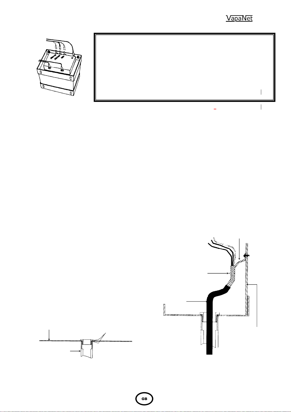
1.2 Positioning the steam pipes
1.2.1 General
Steam pipes should be positioned as shown below,
allowing a minimum rate of fall back to the unit of
12% to allow the free flow of condensate back to the
unit. If the above fall is not possible, then
condensate separators must be fitted as shown in
figure 1.
The position of the steam pipe or multipipe in a air-
conditioning system relative to other items such as
bends, filters, heat exchangers, etc., is critical. The
steam pipe must not be located closer to such item,
than the entrainment distance, and must be decided
by the design engineer responsible for the project.
Do's
Do obtain project engineer's instruction/drawing for
chosen location of pipe
Do obtain project engineer's instruction/drawing for
pipe position relative to the top & bottom of the
duct (or sides if airflow is vertical.
Do check if alternative slope of Ø35mm pipe has
been specified requiring rotation of pipe in its
socket before installation.
Do use bracket/lug on the end of Ø54mm pipes for
extra support.
1.2.2 Steam Hose Connection
Do's
Do use Vapac steam hose or well insulated copper
pipe.
Do keep steam hose as short as possible (under 2m
for max efficiency).
Do arrange to have a vertical rise immediately over
the unit of 300mm.
Do use the full height available between the unit and
steam pipe to provide maximum slope (min 12-
20% for condensate to drain back to the steam
cylinder (or down to a condensate separator).
Always provide a continuous slope.
Do provide adequate support to prevent sagging
a) fit pipe clips every 30-50cm
or b) support straight lengths on cable trays or
in heat resistant plastic pipe.
Do ensure radius hose bends are fully supported to
prevent kinks developing when in service.
Do add extra insulation to steam hose for longer
runs (2m-5m) and in cold ambient conditions to
avoid excess condensate and reduction in
delivered output.
Don'ts
Don't allow steam hose to develop kinks or sags.
Don't include horizontal runs or 90oelbows in the
steam line.
Steam Distribution Pipe requirement
Resistance Heater
Unit Model LR05
LR10
LR05P
LR10P
LR20
LR30
LR20P
LR30P
LR40
LR50
LR60
LR40P
LR50P
LR60P
35mm
Pipe No.
54mm ∅. Pipe No. 1
- -
1 -
2
* Duct Pressure Pa. +2000
-600 +2000
-600
* For systems with a duct pressure over +1000 Pa. It may
be necessary to fit a suitably sized trap in the water feed
line between the Vapac tundish and the feed drain
manifold to ensure water can enter the cylinder when it is
empty.
35mm
Pipe Selection 54mm ∅Pipe Selection
Duct width
B mm In-duct Length
L mm Duct width
B mm In-duct Length
L mm
320-470
470-620
620-770
770-920
920-1070
1070-1200
300
450
600
750
900
1050
700-950
950-1450
1450+
(Kg)
650 (1.8)
900 (2.2)
1400 (3.2)
For guidance on positioning of steam pipes see
Appendix 1.
For guidance on use of Multipipes see Appendix
2.
R min for 35
Pipe = 250mm
R min for 54 ∅Pipe = 500mm
Flexible Steam
Pipe.
No Sags!
Distance to first
bend.
VAPAC
HUMIDIFIER
Flexible Steam
Pipe.
Flexible pipe coupling to
connect Steam pipe to Duct
pipe coupling length to allow
for line movement and
expansion. Coupling clamp
with Hose clips each end.
35 or 54 mm
copper or
stainless steel
steam pipe with
Insulation.
Fig 6