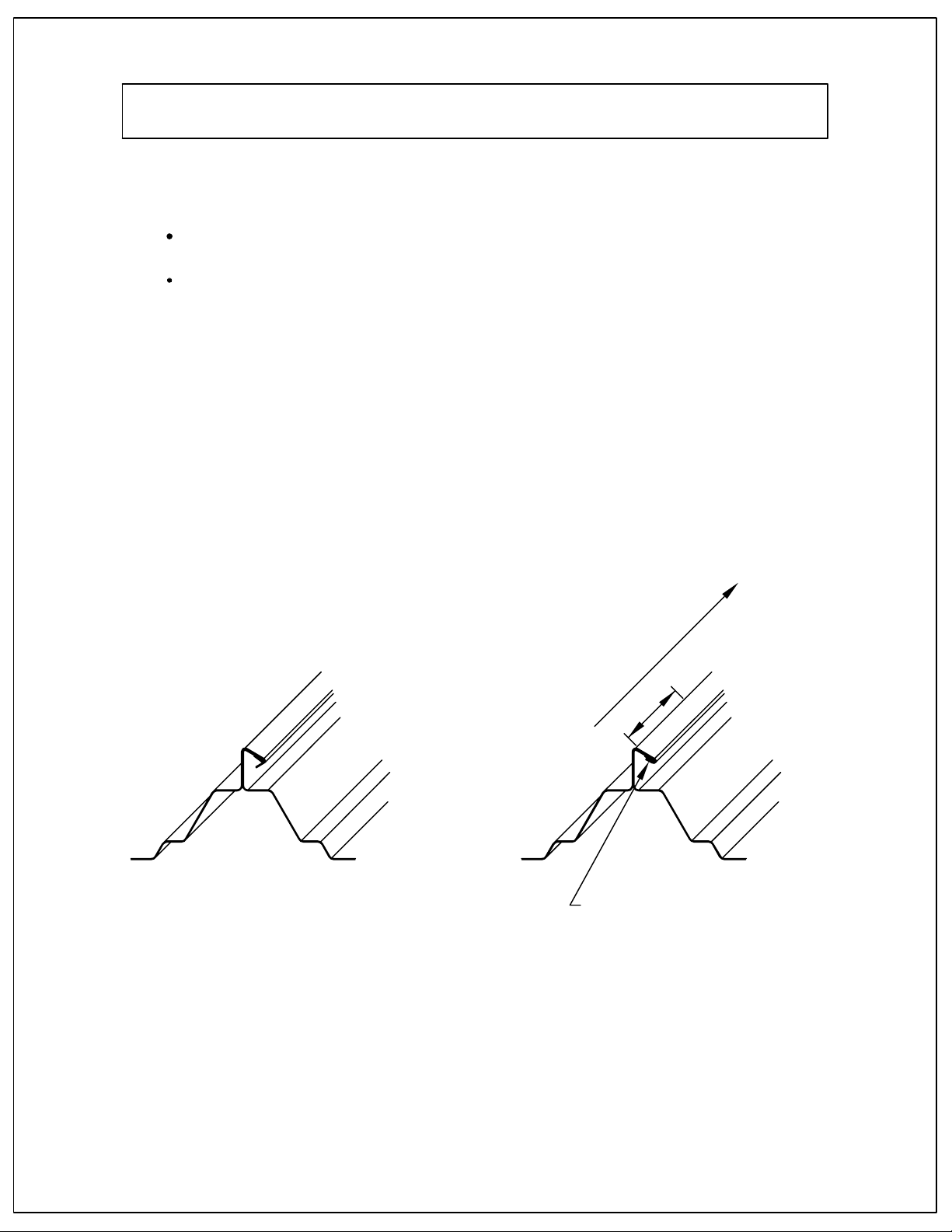
VARCO PRUDEN SSR 900 User manual

VARCO PRUDEN BUILDINGS
SSR 900 Seamer Tool Manual
The field guide for proper use of the Model 900 SSR Seamer Tool.


The builder/Erector remains solely responsible for the
safety and appropriateness of all techniques and methods
utilized by its crew in the erection of the VP building.
The Builder/Erector is also responsible for supplying any
safety devices, such as scaffolds, runways, nets, etc. which
may be required to safely erect the metal building system
and to perform the SSR-Seaming Operation.
Unplug the electrical power source before performing
any service on the seamer tool.
Check and maintain all electical cords and connections.
Power source and electrical cords should have a 3 wire
grounding system.
Discontinue seaming operation in damp, wet conditions and
other undesirable weather conditions.
Provide safe operating procedures along edges of roof,
tuf-lites, and other roof openings.

1. SSR Seamer tool Kit Components.............................................2
2. Basic Description.......................................................................3-4
3. Power Source............................................................................5
4. Preparation for Seaming............................................................6
5. Seaming Operation/Start...........................................................7-10
6. Field Maintenance/Troubleshooting..........................................11-13
7. Seaming Information.................................................................14
8. Hand Crimping/Information.......................................................15
1. VP-SSR Hand Crimping Tool...................................................17
2. Uses of Hand Crimping Tool....................................................18
3. Step 1: Positioning...................................................................19
4. Step 2: Crimp Female Leading Edge.......................................20
Item
Item
Page No.
Page No.
1
9. Seamer Adjustment..................................................................16

1. SSR Seamer Tool With Handle Assembly
2. Field Manual
3. One (1) Finish Seam Gauge & Instructions
4. Shipping Box. Save for
Storage & Shipping.
VP-Tool
Serial
No.
Model No. VP-900
2
Do Not Discard.
1. SSR SEAMER TOOL KIT COMPONENTS

1. The SSR Seamer Tool is a special precision designed and built, portable
roll-forming machine.
2. The Seamer Tool is lightweight 38lbs.
3. Forming speed is capable of 25 surface feet per minute.
4. Power required: 20 Amp breaker minimum.
5. Control: on/off switch, forward single speed.
DownSlope
6. Each of the three (3) sets forming rolls and one (1) guide roll perform a part
of the seaming operation.
6
3
5 4
12
Clamping Handle
PLAN VIEW
FORMING ROLLS
As viewed from bottom
Moveable
Fixed Side
Front
Side
Model No. VP-900
Seaming
3
2. BASIC DESCRIPTION

8. Guide Roll and Forming Rolls.
a. Front Guide Roll-Fig. 1
When seamer tool is clamped on seam
correctly, guide roll should be in
position as shown.
b. First Set (Rolls #1 & 4)-Fig. 2
Tuck the female lip under the male lip
and begin to pull the seam together.
c. Second Set (Rolls #2 & 5)-Fig.3
Force the two parts of the seam together
and begin the finishing process.
(#2 roll-fiber roller)
d. Third Set (Rolls #3 & 6)-Fig. 4
Finish the seaming process by compressing
the seam.
FIG. 1
FIG. 2
FIG. 3
FIG. 4
41
52
63
Top Guide
Roll
Model No. VP-900
4
2. BASIC DESCRIPTION (CONT'D)

Model No. VP-900
5
3. POWER SOURCE
1. The 3 station roof seamer motor requires a 20 amp, 100-125 volt AC power
supply. Poor performance and motor damage can result from use of an
improper power supply.
Recommended extension cord size:
Distance (FT) 0-50 50-100 100-200 200+
Wire Gauge (AWG) 12 10 8 6
No other power tools should be run from seamer tool cord during seaming
operation.
2. Check Power Source, if seamer tool slows down or voltage
appears to drop.
A. There are three (3) possible reasons:
1. A lower rated cord than required is being used.
2. The power source is too far from seaming area.
3. Make sure no more than one (1) electrical power tool is
being operated off the single power source that is required for
the seamer tool.
3. Electrical requirements for 3/4 H.P.-10 Amp motor
A. 115 volt (minimum) - 60 cycle single phase
B. 20 Amp breaker minimum

3
4
2
1
MALE RIB
SEALANT
FEMALE RIB
SEALANT
FEMALE RIB
MALE RIB
FIG. 1
CORRECT
FIG. 1 INCORRECT
FIG. 2
Model No. VP-900
6
4. PREPARATION FOR SEAMING
A. Check Seamer Tool
1. Check seamer tool for Grease.
When in use, tool should be
lubricated every day. If seamer tool
is in sustained, continuous use,
grease every four (4) hours. Only
one (1) shot of grease required at
each point shown (1, 2 & 3).
2. Lubricate tool at grease fittings,
using only "Lithium Grease". See
figure 1 for grease fittings locations.
3. Clean forming rolls with WD-40 to
remove dirt, excessive grease and
sealant build-up on rolls.
Clean Mastic from rollers daily.
4. Check tool for loose parts, screws,
wheels, forming rolls, and electrical
connections. Repair & replace
as required.
5. Lubricate drive chain, which is
enclosed under rear chain cover.
Loosen and remove one (1) set
screw from cover. Apply one (1) shot
of grease to each drive sprocket as
required after 8 hour use
(see figure 4 above).
B. Panel
1. Panels should be wiped down at the areas where tape
mastic or tube sealant is to be applied.
2. BEFORE SEAMING, IT IS IMPORTANT TO WIPE THE
SEAM CLEAN WITH SOAPY CLOTH IMMEDIATELY
BEFORE SEAMING THE PANEL. THIS STEP WILL
DRAMATICALLY REDUCE THE CHANCE OF MARRING
THE SEAMS AT THE CLIP LOCATIONS.
3. Check seams to ensure they are engaged prior to
seaming. See Figure 1 - Correct and Figure 2 -
Incorrect below

NOTE:
Start SSR-Seamer Tool is designed to operate one direction only.
See caution and safety information in front of this manual
TO BEGIN SEAMING OPERATION
1. Ensure proper engagement of the male and female hems.
Hand crimp with VP hand crimping tool or channel lock type
SEAMDIRECTION
1"
TUCK SEAMPROPER ENGAGEMENT
pliers. (See Hand Crimping/Information)
Model No. VP-900
7
5. SEAMING OPERATION/START

Panel
Edge First (2) Stands
of Rollers
Panel
Edge
6 5 4
3. Clamp handles 4, 5 & 6 down to the locked position.
2. Position seamer on the beginning edge of the SSR
Panel, so that the first two stands of rollers
straddle the seam and rest on the panel.
6 5 4
Model No. VP-900
Direction of Seamer
Travel
Direction of Seamer
Travel
Clamp Handles
Down
8
5. SEAMING OPERATION/START

6 5 4
0.38" Max
PROPER SEAM PROFILE
AFTER SEAMING
4. Turn Power Switch on and run seamer about 4 inches.
Check seam to ensure proper seaming operation.
5. After seam is checked and proper operation is verified,
continue to seam remainder of panel, inspecting seam
continuously. Seamer should travel approximately 25 feet
per minute.
6. When the seamer tool approaches the end lap, "STOP"
the seamer tool before crossing the End Lap and hand
crimp the leading edge of female lip. Also, it will slow
down due to the additional thickness of metal. This
heavier load requirement can be detrimental to the
seamer tool if it should come to a complete stall. The
operator should assist by manually pushing the seamer
forward by the handle until the seamer clears the lap.
HAND CRIMPING AT START OF SEAMING OPERATION:
CRIMPING THE FEMALE LIP OF SEAM INTO POSITION.
7. When approaching the end of the panel, use extreme
caution, and stop seamer while rear wheels remain on
panel. Roll machine back to a safe working area.
Preform/hand
crimp approx. 1" female lip
TUCK LIP
CHANNEL LOCKS
Model No. VP-900
CAUTION:
9
5. SEAMING OPERATION/START

TUCK LIP
CHANNEL LOCKS
NOTE:
End Lap
A. When the seamer tool approaches
the End Lap, the seamer
tool before crossing the End Lap
and hand crimp the leading edge
of female lip. Also, it will slow
down due to the additional
thickness of metal. This heavier
load requirement can be
detrimental to the seamer tool
if it should come to a complete
stall. The operator should assist by
manually pushing the seamer forward
by the handle until the seamer clears
the lap.
B. Hand crimping at
"Crimping the female lip of seam into position."
NOTE: Starting Seamer Tool at MIDPOINT OF SEAM.
It is possible to start Seamer Tool Model No. VP-900 in the
middle of a seam run; however,it is not recommended.
If required: page 12-item 8-Guide Roll and forming rolls,
figures 1,2,3 and 4.
page 7 and 8 -seaming Operation/Start
Engage rollers, #1 and #4, clamp handle #1 down, advance
seamer tool approx. 2"
Engage rollers, #2 and #5, clamp handle #2 down, advance
seamer tool approx. 2"
Engage rollers, #3 and #6, clamp handle #3 down, advance
seamer tool approx. 2"
seamer tool and check rollers and seams to make sure
they are engaged properly!
Start seamer tool and continue the seaming operation.
items 2,3,4 and 5.
Model No. VP-900
STOP
REVIEW
REVIEW
Start of Seaming Operation.
"STOP"
10
5. SEAMING OPERATION/START

THREADED BOLT
SET SCREW WAHERS
NUT LOCK NUT
SEAMER TOOL
CLAMPING BLOCK AREA
HANDLE
1. If clamping handle is loose and will not clamp, tension has been lost. Check nuts above
washers on turnbuckle bolts. Tighten to "snug", then turn (min. 1/4 turn or max, 1/2 turn)
to tighten or reset properly (see item #7 for alignment).
2. If any worn, broken or bent parts are noticed that hold linkage in and around the adjustable
turnbuckle, contact Customer Service at the VP Buildings Service Center for the rerquired
repair method.
3. When checking tool prior to seaming and during seaming operation, check to see if set
screws at bottom of rolls are tight. Roll may drop down during seaming and damage panel
seam if screws are not tight.
4. If forming roll looks like it has dropped down, but set screw at bottom is tight, do not
remove top plate cover. Contact Customer Service at VP Buildings Service Center for
maintenence procedure.
5. If there are electrical problems with the seamer tool, notify VP Buildings Service Center.
Always have electrical work performed by a qualified electrical repairman.
SET SCREW
IS LOOSE
FORM ROLL
HAS DROPPED DOWN
Model No. VP-900
*TURNBUCKLE
CLAMPING HANDLE ASSEMBLY
11
6. FIELD MAINTENANCE/TROUBLESHOOTING

6
3
5 4
12
Clamping Handle
PLAN VIEW
FORMING ROLLS
As viewed from bottom
Moveable
Fixed Side
Front
Side
FIG. 1 FIG. 2 FIG. 3
415263
7. The alignment of the forming rolls is very important. (See fig. 1, 2 & 3 for proper placement)
Approx. 0.75" gap at top. Roll #1 & 4
Fiber roll touches at bottom. Roll #2 & 5
Approx. 0.11" gap at top. Roll #3 & 6.
1
3
2
8. Drive chain at rear of seamer tool should be checked for tightness (after each 8 hours of use).
a. Remove rear chain drive cover (one (1) set screw).
b. Motor mount brackets are at front & rear of electric motor (two (2) at each end) loosen as
required.
c. Reset tightness of drive chain to "snug" tightness.
d. Reset mounting screws (two (2) at each end) at front & rear motor mounts. Make sure
motor is level or set even.
Front Motor Mount
Adjustable
Motor Mount
Screw
Two (2) set screws
w/slots
Chain Guard
Chain Guard
One (1) Screw
Rear Motor Mount
Adjustable
Two (2) set screws
w/slots Top
Bottom
Drive
Sprocket
Model No. VP-900
12
6. FIELD MAINTENANCE/TROUBLESHOOTING

9. If the seamer tool jumps off the seam, the panel module may be to wide. This lowers
the height of the seam and prevents the proper engagement of the forming rolls and
the SSR panel seams. Panel Module Must Be Maintained. REF: fig. 1,2 and 3.
4 3/4"
HOLD WIDTH
SPREAD
CORRECT
FIG. 2 INCORRECT
FIG. 3
HEIGHT
LOWERED
3"
CORRECT
FIG. 1
24" PANEL MODULE
2 3/8" 2 3/8"
1 7/8"
1 1/8"
3"
FEMALE RIB MALE RIB
Model No. VP-900
13
6. FIELD MAINTENANCE/TROUBLESHOOTING

1. Correct/Incorrect Engaged Seams
Check seams to ensure they are engaged prior to seaming.
2. SSR/Correct/Incorrect Seams & Finish Seam Gauge
0.38" Max
Included with the seamer
tool kit is an SSR "finish
seam gauge". This guage
is to be used to check the
finished SSR seam for
proper compression and
proper seam configuration.
A.
Acceptable
Seam
B.
Acceptable
Seam
C.
Unacceptable
Seam
D.
Unacceptable
Seam
Seam Gauge may not be available
from all Fabrication Centers.
SEALANT SEALANT
FEMALE RIB
MALE RIB
MALE RIB
"Special Note"
1. Check the Finish Seam approximately every
15 feet. On a properly Finished Seam the
gauge should slide on and off easily with no
force required.
2. Special Note: At Endlap Splices and SSR
Panel Clip locations, the gauge will fit
tighter. This is not cause for alarm; the
reason for the tighter fit is because of
added material thickness.
3. See illustrations for acceptable and
unacceptable seams.
Details "A" and "B" are acceptable.
Details "C" and "D" are Unacceptable Seams.
Detail "C" shows the female edge not being
tucked into the seam properly.
Detail "D" shows the female edge flattened to a
vertical leg and has not been tucked into the
seam properly.
If any of the seams correspond to Details "C" or
"D" or the "Finish Seam Gauge" will not fit properly,
refer to the "SSR Seamer Tool, Field Manual." If
problems still are incurred, contact your V.P.
Buildings' Customer Service Department.
FEMALE RIB
Model No. VP-900
14
7. SEAMING INFORMATION

3. Hand crimping/information
A. Hand crimp the following areas with "Channel Lock" pliers, if Hand Crimper
REASON:
1. To ensure proper engagement of forming rolls and rolling guides.
2. To ensure proper start of seaming operation, endlaps and finish end of
B. Hand crimping at
1. "Crimping the female lip of seam into position."
C. Hand crimping at endlap, to ensure
proper engagement of seam, for the
continuing seaming operation.
1. "Crimping the female lip of the
seam together."
D. Hand crimping at finish end of
seam, to ensure the end is
closed off
1. Crimping the complete end
of a finish seam.
SSR Panel Ridge Panels, must also be hand crimped, at the above locations
for proper seamer tool operation and proper finished seam.
Model No. VP-900
Start of Seaming Operation.
NOTE:
15
seamed panel.
8. HAND CRIMPING/INFORMATION
not available, or similar tool.

16
Check the seam width often with the provided seam gage. If the seam gage will not fit on the
seam, stop immediately and adjust the seamer tool. Under normal circumstances, the seamer tool
should require only adjustment of Station #3. If the seam is significantly wider than the seam gage
or the seam is not properly formed, all stations may require attention. Both adjustments will be
described below.
Model No. VP-900
9. SEAMER ADJUSTMENT
CHECKING THE SEAM WIDTH
STATION #3 ONLY ADJUSTMENT
ALL STATION ADJUSTMENT
Set the feeler gage up for a gap setting of 0.075".
Place the feeler gage between rollers #1 and #4. These are the first two rollers from the front
of the machine.
Clamp the handle down. The gage should be snug between the two rollers. If it is not follow
the procedure previously listed to adjust the gap.
Repeat using the same 0.075" gap for station two. This is the station with the fiber roller.
Finally adjust the feeler gage to 0.110" and perform the same operation with the third station.
This should place the machine back into the proper setup for seaming.
Run a small length of test seam and check with the seam gage. If the seam is wide, adjust
only station #3. This is the station at the rear of the machine.
Begin by loosening the set screw on the turnbuckle as shown in the diagram. Due to
differences in seamer tool turnbuckles, no all turnbuckles will be equipped with a set screw.
This is no cause for alarm.
Once it has been determined the set screw is loose or that the turnbuckle is not equipped with
a set screw, remove the bolt that holds the turnbuckle onto the clamping handle. The
turnbuckle can then be pivoted free of the clamping handle.
Rotate the turnbuckle, 1/2 turn counter clockwise to tighten the seam. A 1/2 counterclockwise
rotation of the turnbuckle will tighten the seam approximately 0.015".
Replace the turnbuckle back on the clamping handle. Replace the bolt in the turnbuckle and
tighten the set screw, if equipped.
Place the seamer back on the seam and run a test section. Check the seam with the seam
gage. If the seam is still too wide repeat the procedure until the seam gage will fit properly on
the seam.
For minor adjustments to the tool to reduce seam width, perform this procedure only on station
number three.
If the seam is extremely wide or if the seam is not forming properly, perform the following procedure
using a feeler gage.
1.
2.
3.
4.
5.
1.
3.
4.
2.
5.
6.

Model No. VPHC-17
17
1. VP - SSR HAND CRIMPING TOOL
Table of contents