Varex Imaging Claymount Harmony3 Series User manual

UM19893-EN, Revision: 5.0
www.vareximaging.com
User Manual
Harmony3 series
Docking station

User Manual: UM19893-EN
Harmony3 series
Revision: 5.0
Date of release: 2019-01-29 2/20 www.vareximaging.com
This page is left blank deliberately.

User Manual: UM19893-EN
Harmony3 series
Revision: 5.0
Date of release: 2019-01-29 3/20 www.vareximaging.com
Table of Contents
1. Introduction........................................................................................................................................5
1.1. Contact information .................................................................................................................5
1.2. Abbreviations ..........................................................................................................................5
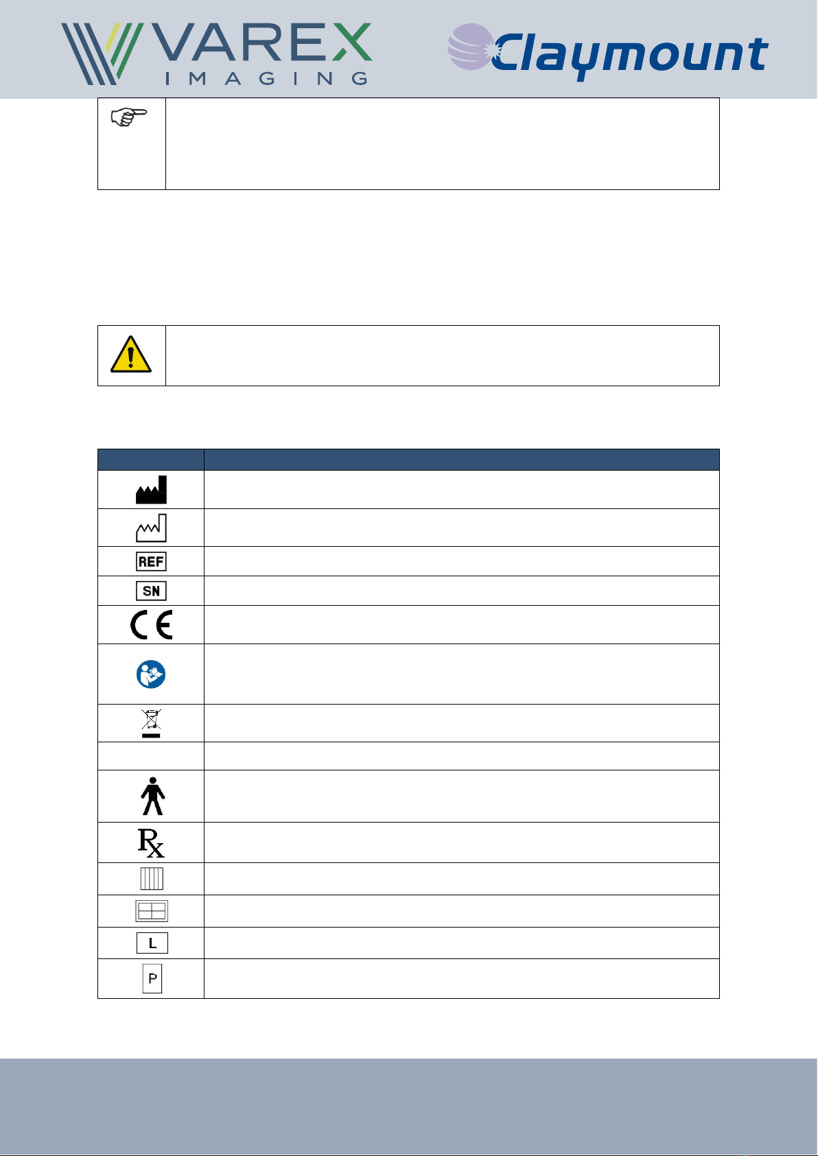
1.3. Symbols used in this document ..............................................................................................5
1.4. Advisory...................................................................................................................................6
1.5. General warnings, cautions and notes....................................................................................6
Requirements for SERVICE PERSONNEL...................................................................................... 7
1.6. Labels and markings on the device ........................................................................................7
1.7. Supplied components..............................................................................................................8
2. Product description............................................................................................................................9
2.1. INTENDED USE .....................................................................................................................9
2.2. Description of the device.........................................................................................................9
2.3. Principle of operation ..............................................................................................................9
2.4. Overview of the device......................................................................................................... 10
2.5. Restrictions on use............................................................................................................... 10
2.6. Attenuation equivalence....................................................................................................... 10
2.7. ESSENTIAL PERFORMANCE ............................................................................................ 10
2.8. APPLIED PARTS ................................................................................................................. 10
2.9. Known contraindication(s).................................................................................................... 10
2.10. Classifications ...................................................................................................................... 10
2.11. Installation .............................................................................................................................11
3. Operating instructions .................................................................................................................... 12
3.1. Switching the device ON and OFF....................................................................................... 12
3.2. Opening the drawer (optional feature) ................................................................................. 12
Inserting the detector...................................................................................................................... 12
Removing the detector ................................................................................................................... 13
Closing the drawer ......................................................................................................................... 13
Changing detector orientation (Optional feature) ........................................................................... 14
3.3. Charging facility (optional feature) ....................................................................................... 14
3.4. Inserting a grid ..................................................................................................................... 14
3.5. Removing a grid ................................................................................................................... 15
Without grid lock option .................................................................................................................. 15
With grid lock option ....................................................................................................................... 15
4. Quality Assurance .......................................................................................................................... 15
5. Maintenance and cleaning ............................................................................................................. 15
5.1. Safety precautions ............................................................................................................... 15
5.2. Preventive maintenance, trouble-shooting and repair ......................................................... 15
5.3. Cleaning ............................................................................................................................... 15
5.4. Disinfection........................................................................................................................... 15
6. Disposal and EMC compatibility..................................................................................................... 16
6.1. Disposal................................................................................................................................ 16
6.2. EMC compatibility ................................................................................................................ 16
7. Specifications and accessories ...................................................................................................... 17
7.1. Technical specifications........................................................................................................ 17
7.2. Labels and symbols on the device ....................................................................................... 18
Product label .................................................................................................................................. 18
Box label......................................................................................................................................... 19

User Manual: UM19893-EN
Harmony3 series
Revision: 5.0
Date of release: 2019-01-29 4/20 www.vareximaging.com
7.3. Accessories .......................................................................................................................... 19
All rights reserved
Although this manual is prepared with utmost care, Varex Imaging Netherlands B.V. cannot be held
accountable for errors or omissions.
Varex Imaging Nederland B.V. cannot be held accountable for damages of any nature arising from the
use, and / or use of any options other than original Varex Imaging Nederland B.V. products.
Warranty
The product has the warranty provisions of our general conditions.
The warranty on your equipment will be void if:
•Service and maintenance are not carried out according to the instructions and if repairs are
not performed, or performed without proper validation.
•Changes or modifications made without our prior written consent.
•Non-original parts or other than the specified lubricants have been used.
•The equipment has been used improperly, carelessly or not in accordance with its nature and /
or purpose.
All consumables (e.g. bolts, nuts, screws, etc.) are excluded from warranty.

User Manual: UM19893-EN
Harmony3 series
Revision: 5.0
Date of release: 2019-01-29 5/20 www.vareximaging.com
1.Introduction
This document is accompanying the Harmony3 series (see also §1.7). Additional to this User Manual a
Technical Manual is supplementary to the INSTRUCTIONS FOR USE.
1.1. Contact information
This manual provides all the technical information necessary for the correct application, operation and
maintenance of the device. Consult the Technical manual for correct installation and service of the
device.
If you need additional information, need support or want to report a problem with the device, please
contact your distributor or Varex Imaging Nederland B.V.:
Manufacturer
Distributor
Name
Varex Imaging Nederland B.V.
Address
Anholtseweg 44,
7091 HB Dinxperlo
The Netherlands
Telephone
+31 (0)315 659 150
Fax
+31 (0)315 659 140
E-mail
Netherlands.CNC@vareximaging.com
Website
www.vareximaging.com
1.2. Abbreviations
Term
Definition
EMC
Electromagnetic compatibility
RAD
Radiology
TM
Technical Manual
ABS
Acrylonitrile Butadiene Styrene
AEC
Automated Exposure Control
NR
Non-Rotating version of the Harmony3 series
ST
STationairy version of the Harmony3 series
1.3. Symbols used in this document
To ensure adequate and clear understanding of the information provided in this manual, the symbols
listed below are used to indicate warnings, cautions, actions and notes that are important for correct
and safe use of the device.
WARNING:
Warnings are directions which, if they are not followed, can cause fatal or serious injuries
to a user, engineer, patient or any other person or can lead to a mistreatment.
CAUTION:
Cautions are directions which, if they are not followed, can cause damage to the device
described in this manual or any other equipment or goods and can cause environmental
pollution.
NOTE:
Notes provide advice and highlight unusual points. A note is not intended as an
instruction.

User Manual: UM19893-EN
Harmony3 series
Revision: 5.0
Date of release: 2019-01-29 6/20 www.vareximaging.com
1.4. Advisory
This manual must be read and understood by the users as defined in the INTENDED USE (see § 2.1)
and SERVICE PERSONNEL.
This manual must be made available to the users and SERVICE PERSONNEL.
The users must verify that all requirements according to the safety standards and regulatory legislation
are met before use of the Harmony3 series.
Information regarding accidents that have occurred using the Harmony3 series must be reported to
Varex Imaging Nederland B.V. immediately.
Varex Imaging Nederland B.V. is not liable if the provided instructions are not complied with. Varex
Imaging Nederland B.V. is not liable if one or more of the following cases apply:
•Modification or repairing of the Harmony3 series in any way other than described in this
manual.
•Use of the Harmony3 series other than the INTENDED USE.
•The Harmony3 series is not subjected to regular inspection and maintenance.
•Use of the Harmony3 series in a way which could not be reasonable foreseen by Varex
Imaging Nederland B.V..
•Direct or indirect damage which are caused by not following the procedures and instructions in
this manual.
1.5. General warnings, cautions and notes
WARNING:
To avoid the risk of electric shock, this equipment must only be connected to a medical
grade power supply. (Not applicable for Harmony3 series NR and ST version)
WARNING:
When there is structural damage to the housing of the Harmony3 series or if the
Harmony3 series is malfunctioning, label the Harmony3 series as “out of order” and have
the docking station repaired prior to further use.
WARNING:
Do not modify this equipment without (written) authorization of the manufacturer.
Any change or modification carried out by unauthorized personnel may introduce serious
hazards. When changes or modification are carried out by unauthorized personnel,
Varex Imaging Nederland B.V. cannot be held responsible for injuries or damage to
equipment.
WARNING:
The Harmony3 series shall only be used with specified conditions listed in §7
WARNING:
Preventive checks (see technical manual) shall be carried on a regular basis. The
interval of these checks shall be tailored to the application and frequency of use.
WARNING:
When there is any damage to the Harmony3 series or repair is needed, only original
replacement parts shall be used. Contact your distributor or Varex Imaging Nederland
B.V. for assistance.
WARNING:
Portable RF communications equipment (including peripherals such as antenna cables
and external antennas) should be used no closer than 30 cm (12 inches) to any part of
the Harmony3 series, including cables specified by the manufacturer. Otherwise,
degradation of the performance of this equipment could result.

User Manual: UM19893-EN
Harmony3 series
Revision: 5.0
Date of release: 2019-01-29 7/20 www.vareximaging.com
NOTE:
Due to the large amount of different types of Harmony3 docking stations, the pictures
used may not always exactly represent the type of docking station that you have. There
are types which do not have a rotation or drawer functionality. Therefore some topics are
not applicable on these types.
Requirements for SERVICE PERSONNEL
The device may only be installed, repaired or serviced by qualified SERVICE PERSONNEL, i.e.:
•Authorized by the RESPONSIBLE ORGANIZATION of the device;
•Authorized by the manufacturer;
•In possession of the diplomas / certificates required by national and local legislation.
WARNING:
Service, maintenance and adjustments may only be executed by qualified SERVICE
PERSONNEL.
1.6. Labels and markings on the device
Symbol
Explanation
Manufacturer.
Date of manufacture.
Catalogue number.
Serial number.
CE-mark directive 93/42/EC.
Follow the instructions for use.
Reading the instructions for use is crucial for a correct and safe use of the
Harmony3 series.
Identification of compliance with the provisions for EU WEEE directive.
IP20
This device has a protection class of IP20.
This device is a Type B Applied part.
CAUTION: Federal law restricts this device to sale by or on the order of a
physician.
Grid present and correctly inserted (optional feature).
Detector Present and correctly inserted (optional feature).
Detector in ‘landscape’ orientation.
Detector in ‘portrait’ orientation.

User Manual: UM19893-EN
Harmony3 series
Revision: 5.0
Date of release: 2019-01-29 8/20 www.vareximaging.com
1.7. Supplied components
The device that you have purchased is packed in a transport box appropriately designed to ensure the
integrity of the device. Please ensure that the package you received is intact and that there are no
traces of moisture or visual damages. Otherwise, you should immediately contact your distributor or
Varex Imaging Nederland B.V..
The transport box contains the following components:
Amount
Description
Reference
1
Harmony3 series
Harmony3 series
Table model: 19407-NN & 19410-NN (**)
Wall model: 19408-NN & 19409-NN (**)
Harmony3 series – ST version
Table model: 20947-NN & 20950-NN (**)
Wall model: 20948-NN & 20949-NN (**)
Harmony3 series – NR version
Table model: 19386-NN & 19389-NN (**)
Wall model: 19387-NN & 19388-NN (**)
1
User Manual
UM19893-EN
1
Technical Manual
TM19379
1
Mounting set for fixed grid
optional feature
(**): The catalogue number contains “NN”, which stands for a sequel number to define the
exact configuration within the applicable model, e.g. other handle, type of drawer, etc.
The main functionality and information is applicable to all sequel numbers within the mentioned
catalogue number.
Be advised by your distributor or Varex Imaging Nederland B.V. for any accessories available.

User Manual: UM19893-EN
Harmony3 series
Revision: 5.0
Date of release: 2019-01-29 9/20 www.vareximaging.com
2.Product description
2.1. INTENDED USE
The device is intended to be used in medical diagnostic applications with restrictions to human
diagnostics. The device is intended to be used as accessory of an X-ray system in a professional
healthcare facility environment. The device is intended to be holding a portable image receptor.
The device is not intended to be used near active HF Surgical Equipment or in the RF shielded room
of a system for magnetic resonance imaging, where the intensity of Electromagnetic Disturbances is
high.
Use, other than above, is identified as abnormal use.
The intended user of the device is defined as the operator of an X-ray system. The operator shall be
qualified and/or trained to operate the X-ray system.
2.2. Description of the device
The Varex Imaging Nederland B.V. Harmony3 series (also known as a Harmony3 series) is a device
which holds an imaging device, such as a digital X-ray detector or film-based X-ray cassette.
The NR version differs from the base model in the following way: the detector can only be placed in a
fixed orientation on the drawer. It is not possible to change the orientation of the detector by rotating.
The ST version differs from the base model in the following way: the detector is mounted inside the
enclosure and cannot be removed by the operator.
The device also provides a slot for mounting a grid and an AEC measuring chamber.
2.3. Principle of operation
The Harmony3 series is a component which is integrated in a regular X-ray system, used for RAD
diagnostic purposes and can be found at the following locations (depending on the version):
•Underneath the X-ray table top, in horizontal position. The device is intended to be integrated
in the table construction.
•Onto a wall stand, in vertical position. The Harmony3 series can also be equipped with a cover
to position a patient against.
The main functionality of the Harmony3 series is to hold several components in order to make an X-
ray image. It contains a facility to mount/fix an AEC-chamber and a facility to place a grid (used for
reducing X-ray scattering) at the correct position. Also, the Harmony3 series NR version hold and
position a portable image receptor. This receptor is placed in a drawer-like construction which can be
pulled out and pushed in the enclosure. The Harmony3 series does not include any of these parts but
only operates as a holder for these components.

User Manual: UM19893-EN
Harmony3 series
Revision: 5.0
Date of release: 2019-01-29 10/20 www.vareximaging.com
2.4. Overview of the device
Harmony3 table model example
Harmony3 wall model example
2.5. Restrictions on use
RF communication devices should be kept at a minimum distance of 30 cm. Otherwise the
performance of the device can be negatively influenced.
2.6. Attenuation equivalence
The Harmony3 series covers have the following attenuation equivalents:
Table model
0.23 mm Al.
Wall model
0.32 mm Al.
2.7. ESSENTIAL PERFORMANCE
The Harmony3 series do not have essential performance.
2.8. APPLIED PARTS
In case of a wall model, the cover is an applied part and consists of ABS. This cover is classified as
type B applied part.
2.9. Known contraindication(s)
There are no known contraindications.
2.10. Classifications
Subject
Classification
Reference
Electrical safety classification
Class I
IEC 60601-1
Emission classification
CISPR11; Group 1, Class A
IEC 60601-1-2
Applied Part
TYPE B
IEC 60601-1
Mode of operation
Continuous
IEC 60601-1
Ingress protection classification
IP20
IEC 60529
Not intended for use in Oxygen Rich environment
Not suitable for Sterilization.

User Manual: UM19893-EN
Harmony3 series
Revision: 5.0
Date of release: 2019-01-29 11/20 www.vareximaging.com
2.11. Installation
The installation instructions for the device are available in the Technical Manual.
For more information, contact your distributor or Varex Imaging Nederland B.V.

User Manual: UM19893-EN
Harmony3 series
Revision: 5.0
Date of release: 2019-01-29 12/20 www.vareximaging.com
3.Operating instructions
3.1. Switching the device ON and OFF
The Harmony3 series does not have a separate switch for switching the device on or off and is
operational when the entire X-ray system is powered on.
3.2. Opening the drawer (optional feature)
Pull out the drawer using the metal handle and by pushing the knob.
WARNING
Always use both hands while opening the drawer: one hand to push the knob next
to the handle and one hand to hold the handle.
NOTE:
It requires some force to overcome the drawer retaining.
NOTE:
The drawer is locked when in the fully opened position.
Inserting the detector
1. Open the drawer.
2. Place the detector as illustrated in the empty drawer.
3. Slide it to the rear against the locking bar and push the locking bar back.

User Manual: UM19893-EN
Harmony3 series
Revision: 5.0
Date of release: 2019-01-29 13/20 www.vareximaging.com
4. Level the detector and lock it behind the grip(s) in the front.
WARNING:
When inserting the detector, make sure the detector is detected correctly. If the detector
is inserted correctly the Detector Present and correctly inserted LED lights up (Optional
feature)
Removing the detector
1. Open the drawer until it locks in its end position.
2. Push the detector backwards and lift it over the front grip(s).
3. Remove the detector from the drawer.
4.
Closing the drawer
1. Push the knob next to the handle to unlock the end position of the drawer.
WARNING
Always use both hands while closing the drawer: one hand to push the knob next to the
handle and one hand to hold the handle.
2. Push the drawer back inside the Harmony3 series.
The LED’s will indicate the position of the drawer (portrait or landscape) and if the image
receptor is present or not. (this is an optional feature)
WARNING
Make sure the detector is at its end position before closing the drawer. Closing the drawer
when the detector is not fully inserted can damage the detector and/or Harmony3 series.
Figure 1: Incorrectly inserted drawer. The
image receptor is not inserted completely
Figure 2: Correctly inserted drawer. The
image receptor is at the right position

User Manual: UM19893-EN
Harmony3 series
Revision: 5.0
Date of release: 2019-01-29 14/20 www.vareximaging.com
Changing detector orientation (Optional feature)
The detector can be moved manually from Portrait to Landscape (and vice versa) without removing
the detector from the drawer.
1. Open the drawer.
2. Seize the detector plate and rotate it 90°.
WARNING:
Be careful of pinching or clamping while turning the detector, always rotate the detector
with two hands.
3. The detector will lock in-place at the new position.
WARNING:
Make sure the detector is locked in its end position before closing the drawer. Closing
the drawer if the detector is not fully rotated can damage the detector and/or
Harmony3 series
4. Close the drawer.
3.3. Charging facility (optional feature)
The Harmony3 series NR version has an optional feature; a fixation facility for a charging / data cable.
This means that when the digital imaging receptor is in position (enclosed in the Harmony3 series) a
wire connection will be established. No special user handling is required for this connection.
3.4. Inserting a grid
CAUTION:
Be careful when handling a grid, if dropped the grid can be damaged. Resulting in a
negative effect on the image quality.
CAUTION:
When not correctly inserted, exams might not be possible.
Only place a removable grid if the “Varex Imaging upgrade-kit” is installed onto the grid.
1. Place the grid in the designated guide rails.
2. Push it in as far as possible.
3. The grid will snap lock into the correct position. Check this by slightly pulling the grid, it should
stay in position. The blue LED will light up. (optional feature).

User Manual: UM19893-EN
Harmony3 series
Revision: 5.0
Date of release: 2019-01-29 15/20 www.vareximaging.com
3.5. Removing a grid
NOTE
In case the Harmony3 series is equipped with the “Internal Lock”-functionality, it is
necessary to push and hold the knob next to the handle before the grid can be
removed.
Without grid lock option
Pull the handle; the grid snaps loose and can be removed from the unit. The blue LED is
switched off. (optional feature)
With grid lock option
Push the grid release button and simultaneously pull the handle; the grid snaps loose and can
be removed from the unit. The blue LED is switched off. (optional feature)
4.Quality Assurance
For the Harmony3 series, there are no quality assurance checks necessary or applicable.
5.Maintenance and cleaning
5.1. Safety precautions
When there is structural damage to the housing of the device, label the device as “out of order” and
have the device repaired prior to further use.
5.2. Preventive maintenance, trouble-shooting and repair
Refer service to a qualified maintenance technician only. See Technical Manual.
5.3. Cleaning
Cleaning with a damp cloth is recommended. Use neutral cleaning products and do not soak the
device with liquid.
5.4. Disinfection
Disinfection with a damp cloth with Isopropyl alcohol is recommended. Before using a disinfectant,
check at a spot on the bottom of the device if the disinfectant will not damage the plastic and coated
metal surfaces.
Do not soak the device with liquid.

User Manual: UM19893-EN
Harmony3 series
Revision: 5.0
Date of release: 2019-01-29 16/20 www.vareximaging.com
6.Disposal and EMC compatibility
6.1. Disposal
This device contains substances that can be hazardous to the environment and care should be taken
when disposed of.
The device is marked with the following symbol:
Follow national and local regulations regarding disposal of electronic equipment.
Packaging material shall be recycled according national and local regulations.
6.2. EMC compatibility
The device conforms to IEC 60601-1-2:2014 for EMC compatibility and must be installed and put into
service according to the EMC information provided in the Technical Manual.
WARNING:
Use of this equipment adjacent to or stacked with other equipment should be avoided
because it could result in improper operation. If such use is necessary, this
equipment and the other equipment should be observed to verify that they are
operating normally.
WARNING:
Use of accessories, transducers and cables other than those specified or provided by
the manufacturer of this equipment could result in increased electromagnetic
emissions or decreased electromagnetic immunity of this equipment and result in
improper operation.
WARNING:
Portable RF communications equipment (including peripherals such as antenna
cables and external antennas) should be used no closer than 30 cm (12 inches) to
any part of the device, including cables specified by the manufacturer. Otherwise,
degradation of the performance of this equipment could result.
NOTE:
The EMISSIONS characteristics of this equipment make it suitable for use in
industrial areas and hospitals (CISPR 11 class A). If it is used in a residential
environment (for which CISPR 11 class B is normally required) this equipment might
not offer adequate protection to radio-frequency communication services. The user
might need to take mitigation measures, such as relocating or re-orienting the
equipment.

User Manual: UM19893-EN
Harmony3 series
Revision: 5.0
Date of release: 2019-01-29 17/20 www.vareximaging.com
7.Specifications and accessories
7.1. Technical specifications
Description
Reference
Classifications
See § 2.10
Application
Holding an image receptor, part of an X-ray system
Materials
ABS, POM, stainless steel, aluminium
Power source (ST and NR version
excluded)
12-42 [VDC] ± 10% / 24 [VA]
Detector/Grid present contact
(Harmony3 series and NR version)
Contact closed when detector/grid is present.
Max. 42VDC @ 2A
Grid detection contact
(Harmony3 series ST version)
Contact closed when grid inserted.
Max. 42VDC @ 2A
Weight
±23 kg (Harmony3 series)
±12 kg (ST version only)
Al eq.
0.23[mm] @ 75[kV] (table models)
0.32[mm] @ 75[kV] (Wall models)
Size
Table: 571x584x69mm (WxDxH)
Wall: 610x610x77mm (WxDxH)
Operation environment
Ambient temperature: 10 – 40 °C
Relative humidity: 10 – 75 %, non-condensing
Atm. Pressure: 690 – 1080 hPa
Storage
Ambient temperature: -10 – +70 °C
Relative humidity: 10 – 90 %, non-condensing
Atm. Pressure: 690 – 1080 hPa
Applicable standards
IEC 60601-1
IEC 60601-1-2
IEC 60601-1-3
IEC 60601-2-54

User Manual: UM19893-EN
Harmony3 series
Revision: 5.0
Date of release: 2019-01-29 18/20 www.vareximaging.com
7.2. Labels and symbols on the device
Product label
1
Manufacturer information
2
Space for applicable (IEC) symbols
3
Model name
4
Catalogue number
5
Serial number
6
Date of manufacture
7
IP classification
NOTE:
The product label as shown is representing the layout and accompanying
explanation. Look at the attached label to retrieve the actual and specific information
of your device.
Medical Device
Anholtseweg 44
7091 HB Dinxperlo
The Netherlands
www.vareximaging.com
IPXX
XXXXXXXXXXXXXXXXXX
XXXXX-XX
WOXXXXXX/E-XX
YYYY-MM-DD
Model:
REF
SN
(01)0XXXXXXXXXXXX(11)XXXXXX(21)WOXXXXXX/E-XX
This product complies with the requirements of 21 CFR Subchapter J for radiation emitting products in effect on the date of manufacture.
Only
1
2
5
4
6
3
7

User Manual: UM19893-EN
Harmony3 series
Revision: 5.0
Date of release: 2019-01-29 19/20 www.vareximaging.com
Box label
7.3. Accessories
The Harmony3 series is supplied without any accessories. The following accessory is available for the
removable grid functionality:
Amount
Description
Reference
1
Upgrade kit, removable grid, 438x480mm
PN 18497
Medical Device
Anholtseweg 44
7091 HB Dinxperlo
The Netherlands
www.vareximaging.com
XXXXXXXXXXX
XXXXX-XX
WOXXXXXX/E-XX
YYYY-MM-DD
Model:
REF
(01)0XXXXXXXXXXXX
(11)XXXXXX
(21)WOXXXXXX/E-XX
Only

User Manual: UM19893-EN
Harmony3 series
Revision: 5.0
Date of release: 2019-01-29 20/20 www.vareximaging.com
Contact details
Varex Imaging Nederland B.V.
The Netherlands
t +31 (0)315 659 150
t +31 (0)315 659 140
Varex Imaging Technology (Beijing) Co., Ltd.
China
t +86 10 6780 2708
t +86 10 6780 2129
f +86 10 6780 2170
Varex Imaging Philippines Inc.
Philippines
t+63 49 5024 520
t+63 49 5024 521
f+63 49 5024 500
f+63 2 8076 472
© 2018 by Varex Imaging Nederland B.V.
All Rights reserved. No part of this document may be reproduced or transmitted in any form or by any
means, electronic, mechanical, photocopying, recording, or otherwise, without prior written permission
of Varex Imaging Nederland B.V..
Table of contents
Other Varex Imaging Medical Equipment manuals