Vari Hurricane F-600 User manual

Mulcher
Hurricane F-600
Instructions for use
2006

F-600
2
Contents
1 Basic information. ..............................................................................................................3
2 Foreword.............................................................................................................................4
2.1 Warning ......................................................................................................................4
3 Operation safety..................................................................................................................5
3.1 Safety regulations. ......................................................................................................5
3.2 Declared noise and ibration alues...........................................................................6
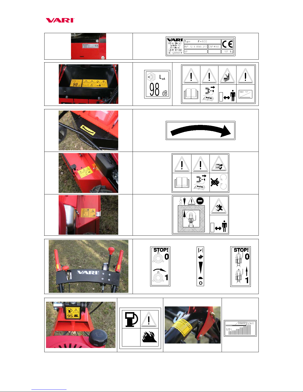
3.3 Safety pictographs. .....................................................................................................6
4 Use, technical specifications and technical description of the machine.............................8
4.1 Machine use................................................................................................................8
4.2 Technical specifications. ............................................................................................8
5 Instructions for use. ............................................................................................................9
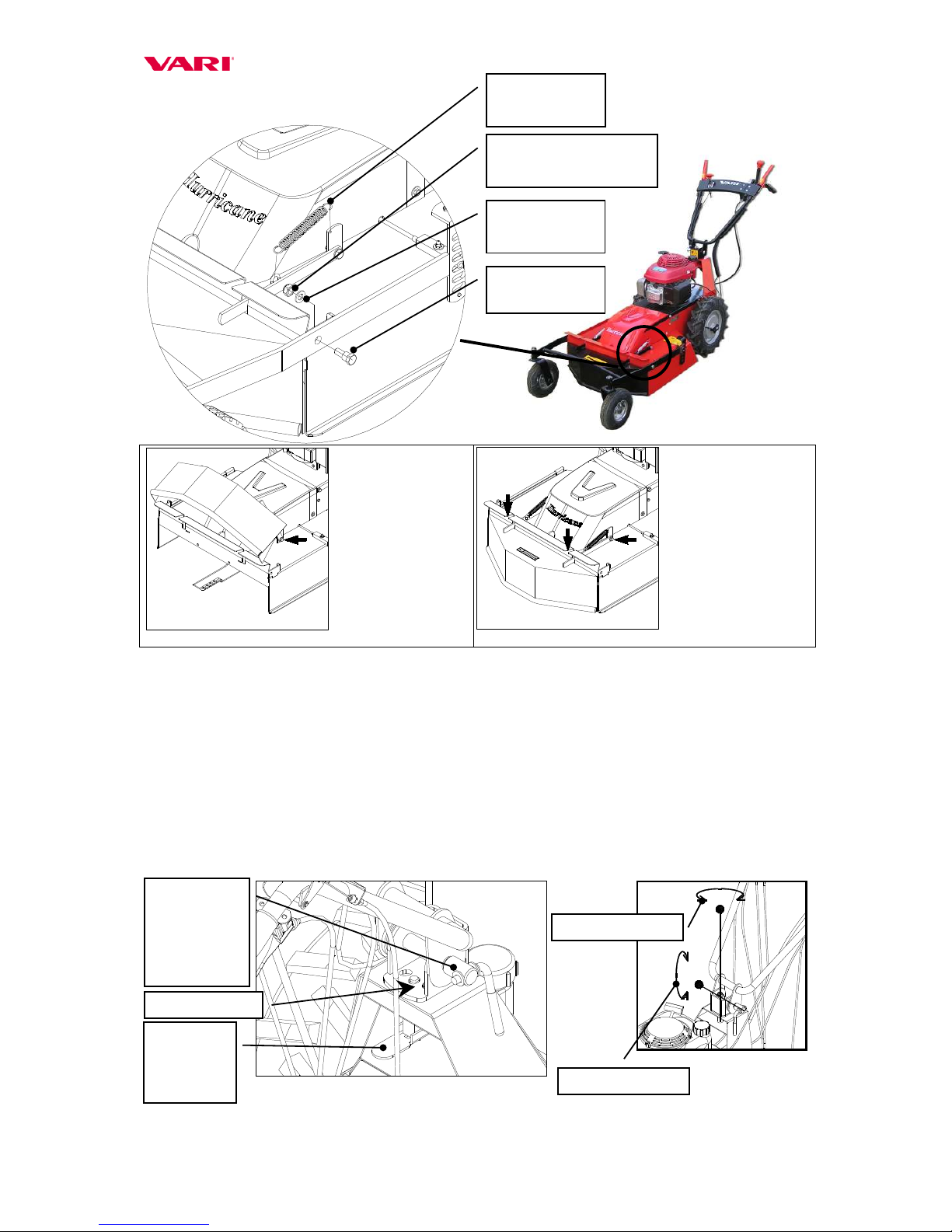
5.1 Machine assembly. .....................................................................................................9
5.2 Adjustment of handlebars.........................................................................................10
5.3 Putting into operation. ..............................................................................................11
5.4 Starting the cutting blade..........................................................................................11
5.5 Machine tra el forward and back. ............................................................................11
5.6 Machine stop.............................................................................................................12
5.6.1 Stopping on the plain........................................................................................12
5.6.2 Stopping on the slope .......................................................................................13
5.7 Working with the machine. ......................................................................................13
5.7.1 Adjustment of cutting height ............................................................................13
5.7.2 Tra el speed choice ..........................................................................................14
5.7.3 Sward cutting....................................................................................................15
5.7.4 Problems at cutting ...........................................................................................15
5.7.5 Cutting on slopes ..............................................................................................15
5.7.6 Machine transport by road................................................................................16
6 Maintenance, care and storage..........................................................................................16
6.1 Machine lubrication..................................................................................................16
6.1.1 Gear oil change and replenishment ..................................................................16
6.1.2 Engine oil replacement .....................................................................................16
6.2 Tightening of bolted connections. ............................................................................17
6.3 Working blade replacement and sharpening. ...........................................................18
6.4 Replacement of V-belts and adjustment of tension pulleys. ....................................18
6.4.1 Replacement of V-belts ....................................................................................18
6.4.2 Adjustment of tension pulleys ..........................................................................19
6.5 Setting up pulley wires, blade brake.........................................................................21
6.6 Adjustment of the automatic brake...........................................................................22
6.7 Table of ser ice operations.......................................................................................23
6.8 Diagnostics of dri ing problems...............................................................................24
6.9 Washing and cleaning of the machine......................................................................24
6.10 Machine storage........................................................................................................24
6.11 Disposal of packaging and machine after the end of ser ice life. ............................25
7 Instructions for ordering spare parts.................................................................................25
8 Contact to manufacturer. ..................................................................................................25
9 The list of parts.................................................................................................................25
10 Letter of Guarantee.......................................................................................................40
Text and illustrations c 2005 VARI,a.s.
Publication No. VL-104-2005
Year on the front page is the year of Manual printing

F-600
3
1 Basic information.
Ask your dealer to provide the machine unpackaging, assembly and setup and the
briefing!
Fill in the following data concerning your machine. The data are important for ordering
spare parts.
It is ad ised to ha e a spare copy of this page with all data on the machine purchase for
the case of loss or theft of the original record.
Model F-600
Commercial name Hurricane
Engine model Honda CV 190
Machine ser. no./Year of manufacture /
Engine serial no.
Date of deli ery (sale)
Supplier
Address
Tel./Fax/E-Mail/Internet
Your notes:
Manufacturer reserves the right of technical modifications and machine inno ations that do
not impact the machine function and operation safety. The changes need not be included in
this Manual.

F-600
4
2 Foreword.
Dear customer and user,
Thank you for trusting our products. You ha e become owner of machine from a wide
range of machines and attachments made by ,a.s. as a system of gardening,
farming, small agricultural and communal technology.
The mulcher Hurricane F-600 is designed to meet the most exacting requirements of
professional use. High-performance engine with a patent-protected cutting edge on the blade
guarantee a problem-free mowing of different sward types. Mechanical gearbox with 3 speeds
in combination with wide tra el wheels and low machine centre of gra ity enable an easy
machine operation e en in the most difficult terrains. Automatic brake and a possibility to
lock guide wheels in forward direction pro ide for a safe operation of the machine namely on
slopes.
Please read the Instructions for use carefully. If you follow them properly, you will
ha e our product performing a reliable work for you for years.
2.1 Warning
The user is obliged to get acquainted with the Instructions for use and to follow all instructions
for the machine operation so that the user’s and other persons’ health and property cannot suffer any
harm.
Safety instructions contained in this manual do not describe all situations or conditions
possibly occurring in practical use. Safety factors such as common sense, diligence and
scrupulousness are not included; it is assumed, howe er, that all persons authorized for the machine
operation or maintenance do possess them.
The machine can be operated only by persons in good mental and physical condition. For the
professional use of the machine the machine owner is obliged to ensure a work safety training and
pro ide instructions on machine control for operators and to keep records on these trainings and
briefings. Also, he is obliged to carry out a so-called categorization of works according to the
relevant national legislation.
Should some instructions in the manual be unintelligible, you are encouraged to contact your
dealer or directly the manufacturer of the machine. The contact address and telephone/fax connection
are to be found at the end of this manual.
The manuals of Instructions for use supplied with the machine are an integral part of the
machine. They ha e to be a ailable at any time, placed at a well accessible place with no risk of their
damage. In the case that the machine is sold to another person, the Instructions for use must be gi en
to the new machine owner. If the abo e conditions are not met, the manufacturer bears no
responsibility for possible risks, accidents and injuries resulting from the machine operation.
The manufacturer bears no responsibility for damages caused by unauthorized and incorrect
use of the machine and for damages caused by any machine modifications not authorized by the
manufacturer.
To pre ent injuries to operators and other people occurring in the icinity of the machine, it is
absolutely necessary to follow safety regulations marked in the Instructions for use with the following
warning safety symbol:
On seeing this symbol in the Manual, read the
following instructions carefully!
Note: Left and right side – as mentioned in the Manual – are at all times meant as iewed
from the site of the operator.

F-600
5
3 Operation safety.
3.1 Safety regulations.
This international symbol indicates important messages concerning safety. When you
see the symbol, be aware of a possible injury threatening to you or to other persons and
read the attached instructions carefully.
The machine operator must be o er 18 years of age. He (she) is obliged to get
acquainted with the instructions for use of the machine and is supposed to be informed
of the general principles of work safety.
Prior to carrying out any acti ities in the near icinity of the machine, switch the
engine off and wait until the cutting blade stops mo ing! Before lea ing the machine
alone, always switch off the engine!
Ne er let the engine running at maximum speed or idling for a long time with the
cutting blade and tra el wheels dri e clutch switched off! Components of the machine
dri e (V-belt, belt pulley, clutch pulley, etc.) might get damaged!
Prior to each employment of the machine, check its parts (working mechanism or its
casing in particular) for a possible damage or loosening. Defects must be rectified
without any delay. Repairs are to be made only with the original spare parts.
Before using the machine, the stand to be cut must be cleared of solid bodies such as
stumps, branches, stones, wires, loose construction debris, etc., which could be flinging
up or which might damage the machine. If these cannot be remo ed, a oid working in
such places.
The machine is equipped with a rotating working implement. Maximum
circumferential speed is 72,3 m.sec-1. Therefore, make sure that other persons mo e at
a safe distance from the machine when it is in operation with regard to a possible flying
away of the cut stand or flung out solid objects!
With respect to the exceeded recommended alues of noise and ibrations, you are
warned to obser e the following instructions when working with the machine:
a) Protect your hearing by using suitable protecti e aids specified in CSN EN
352-1 (shell ear protectors) or CSN EN 352-2 (plug ear protectors). Require
the aids from your dealer.
b) Working with the machine should be interrupted after max. 20 minutes for a
minimum break of 10 minutes. During these breaks, the machine operator must
not be exposed to the impact of another source of noise or ibrations.
Machine operators should use working aids authorized to CSN EN 166 or CSN EN
1731 (tight-fitting garments, sturdy shoes, working glo es and protection glasses).
Keep a safe distance gi en by the handlebar.
Don’t start the engine in enclosed spaces! Pay increased attention when handling the
machine since the exhaust silencer remains hot after the engine has been switched off;
make sure there are no leakages and spills on engine parts when refuelling. If they
happen to occur, dry out the stained parts or wait until the petrol e aporates.

F-600
6
When the machine is in operation, all other persons (children in particular) and animals
ha e to be outside the machine’s working space. The machine operator can continue
working only after they ha e been shown out to a safe distance (see Pictograph 6).
NOTE: The outer safety zone A around the inner working zone B is specified in standards EN 12733
and CSN EN 12733. Entry into the working zone is to be pre ented by using appropriate prohibitory
signs. Distance between the indi idual sides of zones A and B must not be less than 50m. Should the
dangerous zone of machine operation be entered by a person or animal, the machine operator must
release the cutting implement dri e le er without any delay and wait with the further work until the
zone is clear again.
Remo al of any protecti e equipment and casings from the machine is forbidden.
The safe slope accessibility of the machine is 10°. Maximum inclination of the engine at
work is 20° for a long-time operation and 30° for a shorter time (up to 1 minute).
NOTE: The machine should be preferably not used on wet grass. The terrain you are mo ing on must
be always safe. Do the work while walking not running. Be particularly careful when changing
direction on the slope. Cutting on steeply inclined slopes should be pre ented. If you fall, do not hold
the machine but release your grip on it.
All kinds of the machine repair, adjustment, lubrication and cleaning are to be made with
the machine switched off and spark plug cable disconnected.
3.2 Declared noise and vibration values
Hurricane F-600 A B C
HONDA GCV 190 LpAd = 84+1 dB LWA = 98 dB ah d = 7.3+2.92 m.s-2
Explanatory notes:
A = declared emission le el of acoustic pressure A at operator’s site LpAeq,T (according to ČSN EN 12733,
Attachment B and ČSN EN ISO 11 201)
B = guaranteed le el of acoustic performance of the machine LWA (according to Go ernment Regulation no.
9/2002 Gaz.)
C = declared sum of accelerated ibrations transmitted onto operator’s hands/arms (according to ČSN EN 12733,
Attachment 6, Point C.4.1.1.1 and ČSN EN ISO 20643).
3.3 Safety pictographs.
The user is obliged to maintain the pictographs on the machine legible and to pro ide
for their replacement in the case of damage.
No.
Location Description of the safety information
1 Left side of chassis Manufacturing label with machine information and CE sign
2 Guaranteed le el of machine’s acoustic performance
3 Upper co er of gearbox Instructions for use to be studied prior to machine operation and maintenance
During the machine maintenance the conductor is to be disconnected from the spark plug
Entry of exposed and other persons into the machine’s working space is prohibited
Safe slope accessibility
4 Front lifting co er Arrow for the direction of tool rotation – to the right
5 Left rear side of blade
co er upper surface
Instructions for use to be studied prior to machine operation and maintenance
During the machine maintenance the conductor is to be disconnected from the spark plug
Putting one’s hands or feet into the cutting blade working space is prohibited – Danger of
limb cut (off)
6 Right rear side of blade
co er upper surface
Entry forbidden for other persons and animals. Minimum safe distance from the machine.
Danger of injury by flying-off material fragments and flung objects. Other persons and
animals to be kept at a safe distance from the machine.
7 Right control le er Cutting blade dri e switch. “0” = blade does not turn, “1” = blade in rotation
8 Next to accelerator le er Le er positions for adjustment of engine rotations
9 Left control le er Machine tra el switch. “0” = machine stands still, “1” = machine tra els
10 Swi el handlebars holder
Danger of fire when refuelling
11 In front of right rubber
handle
Adjustment of minimum and maximum cutting height

F-600
7
1
2
3
4
5
6
7
8
9
10 11

F-600
8
4 Use, technical specifications and technical description
of the machine.
4.1 Machine use.
This mulcher is designed for mowing swards of all kinds of stalky grasses, preferably
old and dry, on both maintained and not-maintained sites. The mulcher can be used for cutting
woody species from self-seeding up to a diameter of 1.5 cm. Periods most suited for the
machine use are those when the swards are dry and the cutting blades are capable of crushing
them into small pieces which need not be remo ed from the surface. The maximum
recommended height of swards emerged in the same period when cut is up to 50 cm. This
maximum height may decrease according to sward density, moisture content and type.
Working width must be at all times accommodated to the density of the mown
sward.
With respect to tyre profile and system of cutting height setup, the machine is not
designed for park treatment of green areas.
4.2 Technical specifications.
Hurricane
F-600 Unit Value
Length (inc. handlebars) mm 1940
Width mm 640
Height (incl. handlebars) mm 1190
Weight kg 107
Maximum working width of the machine cm 57
Cutting blade adjustment height abo e solid underlay cm 5 – 9
Blade speed (at max. engine re olutions) min-1 2424
Circumferential blade speed (at max. engine re olutions) m.s-1 72,3
Tra el speeds (at max. engine re olutions) km.h-1 1.42 – 2.16 – 3.79 – R 2.74
Area performance of the machine (according to sward type and
tra el speed) m2/h 809 – 2160
Engine Unit
Type HONDA GCV 190
Cylinder olume cm3 187
Bore x stroke mm 69 x 50
Max. performance at re olutions kW/min-1 4.8/3600 (6.5 HP)
Max. torque at re olutions N.m/ min-1 13.2/2500
Max. engine re olutions adjusted min-1 3400 (+/- 100)
Fuel tank capacity litres 1.1
Petrol (unleaded) oct.no. 91-95
Oil filling litres 0.55
Oil API SH or SJ
Spark plug -- NGK BPR6ES
BRISK LR15YC

F-600
9
Figure 1: Mulcher Hurricane F-600
Instructions for use.
5.1 Machine asse bly.
Ask your dealer to pro ide unpackaging of the machine and briefing in machine operation.
With respect to difficult withdrawal of the machine from the box, it is ad ised to cut
the box through in corners and then to take off the machine onto a fixed rest. Grip points:
front – blade co er edge, rear – tube of handlebars grip. Regarding the machine weight, work
with a minimum of one other person.
If you assemble the machine yourself, please follow the instruction below:
1. Remo e all parts from the bag and the leading wheels from the machine.
2. The front lifting co er is mounted abo e the chassis deflector because of the packing
reason; to achie e correct functionality of the machine, it is necessary to dismount it
and mount it back under the chassis deflector, see fig. 2.
3. Unloose the tightening nut on the handlebars (see fig. 3, position 1) and put the
handlebars to the working position. Turn the handlebars anti-clockwise around the
ertical axis by 180°, so that the grips point backwards. A oid contortion of the
bowden cables!
4. Hook the springs (1) into eyes in front co er arms and into holes in footings on the
blade co er with a suitable hook.
5. Screw the leading wheels on the footings in the front of the blade co er by means of
bolt (2), flat washer 10.5 mm (3) and self-locking nut M10 (4). When putting the
leading wheels frame into the lock-plate guiding, the locking pin must be pushed in
(by pressing the le er of cutting height adjustment on the right handlebar grip – see
fig. 1).
Accelerator le er
Cutting height adjustment le er
Engine starter grip
Blade co er
Front lifting co er
Leading wheels frame
Front grip point
Leading wheels
Tra el wheels
with pin
differential
Wheel dri e clutch le er
Handlebars
Tightening nut for
adjustment of
handlebars height
Le er of handlebars
side adjustment
Engine
Leading
wheels locking
Cutting height adjustment
Gear shifting le er
Blade dri e le er

F-600
10
Figure 2: Machine assembly
Unscrew the front
co er from the
machine chassis (on
both sides)
Run the front co er
through the cutouts in
the chassis deflector
(the front co er must
crane at the deflector
when lifting) and
screw it back to the
machine chassis.
Tighten the nuts so
that the co er can be
freely lifted.
Mount on the springs.
5.2 Adjust ent of handlebars.
Handlebars can be adjusted in two planes:
• Height: Loosen tightening nut M10 (position (1) in Fig. 3) and do the adjustment of handlebar
grips at height comfortable for the operator.
• To sides: Press down the le er (position (2) in Fig. 3) and turn the handlebars by one position
to the left or to the right.
In order to lessen the machine size e.g. for transport in a car, the handlebars should be either tilted
forward o er the engine or lowered into horizontal position and then turned clockwise by 180°.
Bowden cables must be watched not to get tensioned somewhere on the machine construction.
Figure 3: Adjustment of handlebars
1
Tightening nut
for height
adjustment of
handlebars
Lubrication point
2
Side
arrestment
le er
3
Washer 10.5
4
Self-locking nut M10
2
Bolt
1
Spring (2 pcs)
Side adjustment
Height adjustment

F-600
11
5.3 Putting into operation.
The machine may be delivered without engine fillings (in dependence on different
national regulations)!
First thoroughly read the instruction for engine use. You can prevent a possible
damage to the engine.
1. Check oil olume in the engine and/or fill the engine with the prescribed oil grade and
olume. Fill the tank with the prescribed amount and type of petrol.
2. Mo e the accelerator le er into the front position („CHOKE“). Start the engine by
pulling on the manual starter (instructions for starting see guidelines for engine use).
3. Let the new or cold engine running on choke for about 30 seconds (accelerator le er in the
„CHOKE“ position), and then mo e the accelerator le er into the position „MAX“. In
this position let the engine running for about 30 seconds.
Do not leave the machine alone when doing this!
5.4 Starting the cutting blade.
When starting the engine, the two levers on the handlebars must be in the off
position.
1. Start the engine while adhering to instructions presented in the operating manual for
engine use.
2. Set-up maximum engine rotations by using the accelerator le er in the right part of the
handlebars crossbar. (Should the engine be cold, let it warm up at maximum rotations for
about 1 minute).
3. Grasp the left handlebar grip with your left hand. Then slowly press the cutting blade
dri e clutch le er on the right handlebar grip with your right hand.
Press the lever slowly up to about two thirds of the stroke so that the cutting blade
can start rotating and the engine does not stall.
Starting of the cutting blade is accompanied with a partial V-belt slippage and with the
accompanying phenomena such as whistling, rattling, etc. The phenomenon usually
disappears after the belt has started properly mo ing.
4. After the cutting blade starts turning, press the le er completely to the handrail and hold it
firm.
Note: If the blade dri e is switched on during cutting again, engine stalling may occur due to
resistance of grass biomass in the space of blade co er. This space must be –if possible – always
properly emptied when starting the blade dri e (see Chapter 5.7.4).
In a new or cold engine, a few of the cutting disk starts may result in engine stalling. The
phenomenon will disappear after the engine warms up. If the disk dri e cannot be started e en
after the engine has got warm, follow the table presented in Chapter 6.8 for diagnostics.
5.5 Machine travel forward and back.
Machine tra el forward and back is controlled by the upper red sheet-iron le er on
the left grip of the handlebars.
• Travel forward: Shift into one of gears (1 - 3) by using the gear-shifting le er. Then
press the upper red sheet-iron le er on the left handrail completely down to the grip and
the machine will start mo ing forward (sometimes with a little delay due to the run-out of

F-600
12
the pin differential in wheels). Start walking simultaneously with the machine start,
adapting your walk pace to the direction and speed of the machine.
Be prepared when the machine starts moving with a little jerk.
• Travel back: Mo e the gear-shifting le er to the „R“ position. Then press the upper red
sheet-iron le er on the left handrail down to the grip and the machine starts mo ing in
re erse direction (sometimes with a little delay due to the run-out of the pin differential in
wheels). Start walking simultaneously with the machine start, adapting your walk pace to
the direction and speed of the machine.
Be very careful when moving backwards with the machine!
Start driving with approximately ½ of maximum engine revolutions if you want to
travel backwards. After the machine is in motion, set the engine revolution on the
level, which ensures that your walking pace is still safe.
Figure 4: Handlebars and control levers
Le er positions of engine speed
setup
STOP MIN
MAX CHOKE
Note: All four main positions of engine speed adjustment le er are arrested by means of a
simple system (dent/rib) in the le er body.
5.6 Machine stop.
5.6.1 Stopping on the plain
If you wish to stop the machine tra el, release the le er on the left handlebar grip. The
machine will stop mo ing but the blade will still turn. The cutting blade dri e will be
switched off after release of the le er on the right handlebar grip. The safety brake will stop
the blade.
Prior to carrying out any activities in the near vicinity of the machine, switch off the
engine and wait until the cutting blade stops! Always switch the engine off before
leaving the machine!
Never let the engine running at maximum speed or idling with the cutting blade
drive clutch released and with the released clutch of travel wheels drive for a long
Blade and brake dri e
clutch le er
Accelerator le er (engine speed adjustment)
Leading wheels adjustment le er (cutting height)
Gear-shifting le er
Le er of
machine tra el
clutch and
automatic brake

F-600
13
time! Machine drive components (V-belt, belt pulley, clutch pulley, etc.) might
suffer damage!
If you wish to switch the engine off, do it by shifting the le er to the „STOP" position.
In the case of any critical situation, release your hold on the handlebars without any
delay. Do not hold on the machine! The levers will return to their zero position, the
machine and the cutting blade will stop (while the engine is still running at set-up
revolutions; this is why it is to be switched off by shifting the lever to the „STOP“
position as soon as possible!)
5.6.2 Stopping on the slope
The machine is equipped with an automatic brake, which – if properly adjusted – will
safely put the machine to stop on a slope up to 30°. The automatic brake is put into operation
after releasing the machine tra el clutch le er on the left handlebar.
Never let the engine running at maximum speed or idling with the cutting blade
drive clutch released and with the released clutch of travel wheels drive for a long
time! Machine drive components (V-belt, belt pulley, clutch pulley, etc.) might
suffer damage!
5.7 Working with the achine.
Before using the machine, the stand to be cut must be cleared of solid bodies (such
as stumps, branches, stones, wires, loose construction debris, etc.), which could be
flinging up or which might damage the machine. If these cannot be removed, avoid
working in such places.
Working width has to be at all times accommodated to stand density!
If possible, do not use the machine on wet grass. Remember that the terrain you are
moving on must always be safe. Walk (never run) at work. Be careful especially
when changing the machine direction on slopes. Do not cut on steep slopes. When
accidentally falling, immediately release your hold on the machine.
5.7.1 Adjustment of cutting height
Adjustment of cutting height is affected by se eral important factors:
• sward height and density
• plant species pre ailing in the sward
• machine tra el speed
• working width
• surface une enness
There is a general rule that the higher alue of abo e mentioned factors, the greater height
of guide wheels and cutting blade height adjustment abo e the surface. The cutting height
should pre ent o erfilling of the blade working space as such a situation reduces the blade
speed, the engine cannot work at optimum re olutions and the self-cleaning capacity of
cutting blade space from accumulated grass biomass is impaired.
Prior to working a terrain irregularity, increase at all times the cutting height to the
very maximum. In this way you will prevent blade damage.

F-600
14
Cutting height adjustment by means of guide wheels:
a) push on both handrails so that the arresting pin in the arresting plate is released
b) press the black plastic le er of cutting height adjustment on the bottom side of the
right handlebar grip with fingers of your right hand (see Fig. 4).
c) reduce or increase the height of guide wheels adjustment by pushing on the two
handrails
d) adjust one of o al holes on the arresting plate against the arresting pin
e) release the le er
Figure 5: Cutting height adjustment
5.7.2 Travel speed choice
The adjustment of machine tra el speed is ruled by similar factors as the adjustment of
cutting height. The main principle dictates that the greater is the sward density or height, the
lower is the machine tra el speed. Gears are chosen by gear-shifting le er situated on the left
(as iewed from the operator’s site) on the handlebars crossbar. The shifted gear is indicated
by an arrow on the le er against the adjustment line at the gear number on the scale.
ears should be shifted only with the machine travel lever released.
Never change the gear when the machine is moving!
Figure 6: Travel speed choice
3
Maximum working speed.
Low-height or low-density
sward. Good for flat and e en
terrains.
2
Medium working speed.
Medium-height and medium-
density swards. Good for mild
slopes.
1
Minimum working speed.
High and high-density swards.
Good for steep slopes. Cutting of
brushes and self-seeded woody
species.
N
Neutral gear. Engine starting.
Machine transportation by road.
R
Reverse gear.
Position of the highest
cutting height
Position of the
lowest cutting
height
Arresting pin,
lubrication
point
Gear-
shifting
le er.
Arrow
Tra el clutch
le er
Gear scale

F-600
15
5.7.3 Sward cutting
Set the engine on the maximum speed, let the cutting blade rotate at the maximum
speed and then get the machine into motion, facing the to-be-cut sward.
At cutting, you should proceed only in such a way that the to-be-cut sward is – if
possible – on the left side of the machine. When cutting on slopes, it is ad ised to dri e the
machine along the slope contours. Watch a maximum permissible long-term machine
inclination of 20° (30° o er a short-term – up to 30 sec)!
If the cut stand is ery dense, grown through, rotten from below or lodged, the
machine working width must be accordingly reduced, higher cutting height adjusted or
machine tra el speed reduced so that the cutting blade rotations are not excessi ely slowed-
down, which would result in the impaired cutting quality and engine o erloading.
5.7.4 Problems at cutting
Choking of the space under the cutting blade co er with the grass biomass shows in:
a) Engine markedly losing speed but not stalling: machine tra el to be switched off
immediately (le er on the left handrail grip), shift in re erse gear (R), the machine
front to be slightly lifted by pushing down on handrails and mo e the machine slightly
back. The space under the cutting blade co er will do itself a partial clearance from
excessi e grass. Then dri e the machine against the sward again.
b) Engine losing rotations and stalling: release both le ers on the handlebars, start the
engine, shift in re erse gear and back with the machine out from the sward to be cut.
Switch off the engine. Clean the space under the cutting blade space and spread the cut
grass across the ground surface. Start the engine, switch on the cutting blade dri e and
dri e the machine against the sward again.
Be very careful while lifting the machine and driving on reverse gear!
Tilt the machine always only backwards onto the handlebars. Be very careful while
moving under the lifted machine! Secure the machine against its spontaneous
motion and tilt!
Be very careful while cleaning the space under the cutting blade cover. Cutting
edges of the blades are sharp. You should wear protective gloves or use a suitable
piece of branch etc.
5.7.5 Cutting on slopes
If possible, do not use the machine on wet grass. Remember that the terrain you are
moving on must always be safe. Walk (never run) at work. Be careful especially
when changing the machine direction on slopes. Do not cut grass on steep slopes.
When accidentally falling, immediately release your hold on the machine.
The safe slope accessibility of the machine is 10°.
For a better steering control of the machine secure the leading wheels with locking pins
in straight direction. The pins are included in machine accessories. If not to be used, they
should be folded between lugs on the handrail tube. Use medium or minimum tra el speed.
For cutting on slopes up to 20° it is recommended to dri e the machine along the
contour. It is the safest mo ement on the slope. It is also possible to make use of the side
adjustment of handlebars.
On slopes between 20° and 30° ne er dri e the machine in the downhill direction for a
long time. Engine oil filling le el mo es out of sucking points and the engine oiling is
insufficient.

F-600
16
Figure 7: Arrestment of leading wheels on the slope
5.7.6 Machine transport by road
For the machine transport by road shift in neutral gear (“N”) and press the tra el clutch le er
on the left handrail. The automatic brake will be unblocked and the machine can be pushed
manually.
6 Maintenance, care and storage.
To ensure a long-term satisfaction with our product, it must be gi en proper care and
maintenance. Regular maintenance of the machine will pre ent its early wear pro iding at the
same time for a correct functioning of all its parts.
Prior to any machine use, check all bolts and nuts for their correct tightening. Make sure
that all safeguards are in good order. Check the blades, fixing bolts and indi idual elements
of cutting mechanism for a possible wear or damage. In order to keep a good balance of the
machine, worn-out or damaged blades and fixing bolts should be replaced with original spare
parts. All worn-out or damaged components should be replaced also for the reason of
machine safety. Oil le el in 4-stroke engines must range within limits described in the
“Instructions for engine operation and maintenance“.
Follow all instructions concerning the inter als of machine maintenance and adjustments.
It is ad ised that you keep records on the number of machine working hours and on the
conditions in which the machine was working (for ser ice purposes). The after-season
maintenance of the machine should be entrusted to one of our authorized ser ice workshops,
the current maintenance as well if you do not trust your own technical skills.
Regarding the machine weight, all maintenance and adjustment procedures are to
be done by two persons.
6.1 Machine lubrication.
6.1.1 ear oil change and replenishment
Gearbox has permanent oil filling for the entire ser ice life of the machine.
6.1.2 Engine oil replacement
Information is to be found in the Instructions for engine operation and maintenance.
Engine oil a ailable on the Czech market and specially designed for air-cooled engines of
gardening machines is MO UL FORTE ALFA.
When replacing oils, follow the basic hygienic principles, regulations and laws on
environment protection.
Lubrication point
Lubrication point

F-600
17
Table of machine lubrication
* besides lubrication intervals in this table, lubricate the marked points after each water washing, especially when using power water
Figure 9: Other lubrication points
6.2 Tightening of bolted connections.
Regularly check the tightening of all important bolted connections. Always check the
tightening of bolts fastening the blade to the blade holder and blade holder to the shaft prior to
any machine use.
Replacing bolts, use only original spare parts supplied by the manufacturer!
Figure 10: Knife clamping detail
Machine lubrication During
season
After
season Lubricant Figure no.
All wires on the input to Bowdens cables and on
the output from adjustment bolts min 2x * yes silicone oil in atomizer -
Wheel pin and fork on the suspension of leading
wheels min 1x 8 hrs *
yes grease, engine oil 7
Contact area of handlebars with the holder of
handlebars min 2x * yes grease 3
Arresting pin of leading wheels min 1x 8 hrs *
yes silicone oil in atomizer, grease 5
Pin of tension pulleys arm, gear-
shifting le er on
the gearbox min 2x yes grease, engine oil 9
Brake le er seating near the front belt pulley
(after disassembling the plastic co er of the belt) min 2x yes engine oil 9
Tra el wheel hubs min 2x * yes grease -
Bolt M10x20
Tightening torque 48 N.m
NORD LOCK washer 10
Bolt M10x20
Tightening torque 48 N.m
Bolt M10x20
Tightening torque 38 N.m

F-600
18
6.3 Working blade replace ent and sharpening.
The machine must be standing on a firm support plate and must be secured so that
the blade is easily accessible and an unexpected spontaneous machine motion
cannot occur.
Be very careful when dismounting the blade. Its cutting edges are sharp. Protect
your hands with working gloves.
The engine must be switched off and the cable end connector to the spark plug
disconnected!
Working blade replacement procedure is as follows (always work with a helper):
a) Release and unscrew outer bolts „A“. Then release and unscrew central bolt „B“ and
remo e the blade and the blade holder from the blade shaft.
b) Plane the blade and sharpen the cutting edges. Inclination of the sharpened cutting
edge should be 25° with respect to the lower plane of the blade. The blade must be
well balanced after the sharpening; the material loss at sharpening the two cutting
edges should be therefore identical.
c) Mount the blade and the blade holder back onto the blade shaft in a re erse order of
operations.
Central bolt M10x1x25 has a fine thread and therefore it must not be confused with
outer bolts whose threads are normal!
d) Tighten the bolts at a prescribed tightening moment.
Should there be excessive vibrations on the machine handlebars after the
installation, the blade must be unconditionally balanced once again!
Figure 11: Correct sharpening of the blade
Note: Manufacturer does not answer for any damages caused by the machine due to unskilled
repair or treatment of blades without the use of the original spare parts.
6.4 Replace ent of V-belts and adjust ent of tension pulleys.
6.4.1 Replacement of V-belts
V-belts should be replaced according to their wear (cracked sides, torn belt, sides worn
out down to belt carrier fibres, belt “pulled“ out of shape) or after about 200 hours of
operation at maximum. In this machine, belt pulled out to maximum is considered a belt in
which distance between inner belt surfaces (at the pressed le er of the cutting blade dri e
clutch) is less than 7 mm (see Fig. 12).
WRON !!
Upper cutting edge at
maximum grinding off
(max. 35 mm)
CORRECT

F-600
19
Designation of recommended and by manufacturer appro ed V-belts on the machine:
1. V-belt of gearbox dri e: OPTIBELT TX13 x 660Ld 6T6K
2. V-belt of blade dri e: OPTIBELT TX17 x 1290Ld 6T6K
Ld = mean length of the belt
It is possible to use equi alent V-belts made by other manufacturers. Howe er, the V-
belt model must be with no rubber on sides! Only such a model of the V-belt guarantees that
no belt stretching occurs and that the blade dri e starting is smooth when letting-in the clutch.
Should a different belt model be used than the original spare part, the machine
manufacturer cannot guarantee a correct functioning of the transmission!
The procedure of replacing V-belts is as follows:
a) Drain petrol from the engine tank. Unscrew two front M8 bolts and unloose two rear
M8 bolts on the handlebars holder. Tilt the holder together with the handlebars
backwards.
b) Dismount the upper casing of gearbox and the front plastic casing of the belt.
c) Dismount the belt guiding in front of the front dri en belt pulley of the blade.
d) Dismount the M6x35 bolt (see Fig. 12 below) at the tension pulley of the blade dri e
belt.
e) Remo e belts from the dri en belt pulleys (lea ing belts on the dri ing pulley on the
engine). Unscrew four bolts M8 from the engine plate and carefully remo e the plate
from the machine together with the engine and the belts by pulling upwards.
Don’t dismount the bowden cable with the wire of engine revolutions control in any
case!
Never put the engine on the side. Oil might get into the exhaust or into the air
cleaner. The best engine seating is with the lower flange dwelling on two scantlings
that are at least 10 cm high.
f) Replace the worn belts with new ones. It is ad ised that both belts are replaced
together.
g) Assemble the machine in a re erse sequence of operations. Check the adjustment of
both tension pulleys prior to the assembly of casings (see „b)“).
h) Complete the machine assembly.
6.4.2 Adjustment of tension pulleys
Blade drive pulley (Fig. 12)
With the le er on the right handlebar grip fully pressed down, the pulley must ensure a
sufficient belt tension (spring on the cable being extended by about 10 mm as compared
with loose condition). Possible corrections are to be made by means of adjustment bolt No.
2 (see Fig. 14). With the le er switched off, the pulley must be tilted away from the
longitudinal machine axis at an angle of min. 5°. The wire in the Bowden cable of the
tension pulley must exhibit no slackness. In the case that the adjustment bolt is completely
screwed out and it is necessary to tighten the V-belt, the spring on the cable can be hooked
into the front hole on the arm of the tension pulley (see Fig. 12 in the middle; Note: this
connection can be used already from the manufacturer) and belt tension can be adjusted
once again. Guiding plate on the right side of the machine must be parallel to the belt and
at a maximum distance of 1 – 2 mm from the belt con ex side.

F-600
20
Figure 12: Adjustment of blade drive tension pulley and belt guiding at the pulley
Travel clutch pulley (Figure 13)
With the le er on the left handlebar grip fully pressed down, the pulley must ensure a
sufficient belt tension (spring on the cable being extended by about 10 mm as compared
with the loose condition). Possible corrections are to be made by means of adjustment bolt
No. 4 (see Fig. 14). With the le er switched off, the pulley must be parallel to the
longitudinal machine axis. Wire in the tension pulley Bowden cable must not show any
slackness. In the case that the adjustment bolt is completely unscrewed and it is necessary
to tighten the V-belt, the spring on the cable can be hooked into the front hole on the arm
of the tension pulley (Note: this coupling can be used already from the manufacturer) and
belt tension can be adjusted once again. The V-belt must always go between two M6 bolts,
which form the belt guiding when the dri e is switched off.
Guiding pins Guiding plate
Dri en pulley
of blade
V
-
belt
Dr
i ing pulley
(on the engine)
Tension
pulley
Bolt M6x35
Nut M6
Washer
Ø 6.4 mm
Tension pulley
V-
belt of blade
dri e
Dri en belt
pulley
Front guiding
of the belt
Table of contents
Other Vari Lawn And Garden Equipment manuals