Vari Hurricane F-700 User manual

Mulcher
Hurricane F-700
Instructions for use
2007

F-700
2

F-700
3
Text and illustrations c 2004 VARI,a.s.
Publication No. VL-094-2004
Year on the front age is the year of Manual rinting

F-700
4
Contents
1 Basic information ............................................................................................................... 5
2 Foreword ............................................................................................................................ 6
2.1 Basic warnings ........................................................................................................... 6
3 O eration safety ................................................................................................................. 7
3.1 Safety regulations....................................................................................................... 7
3.2 Declared noise and vibration values........................................................................... 8
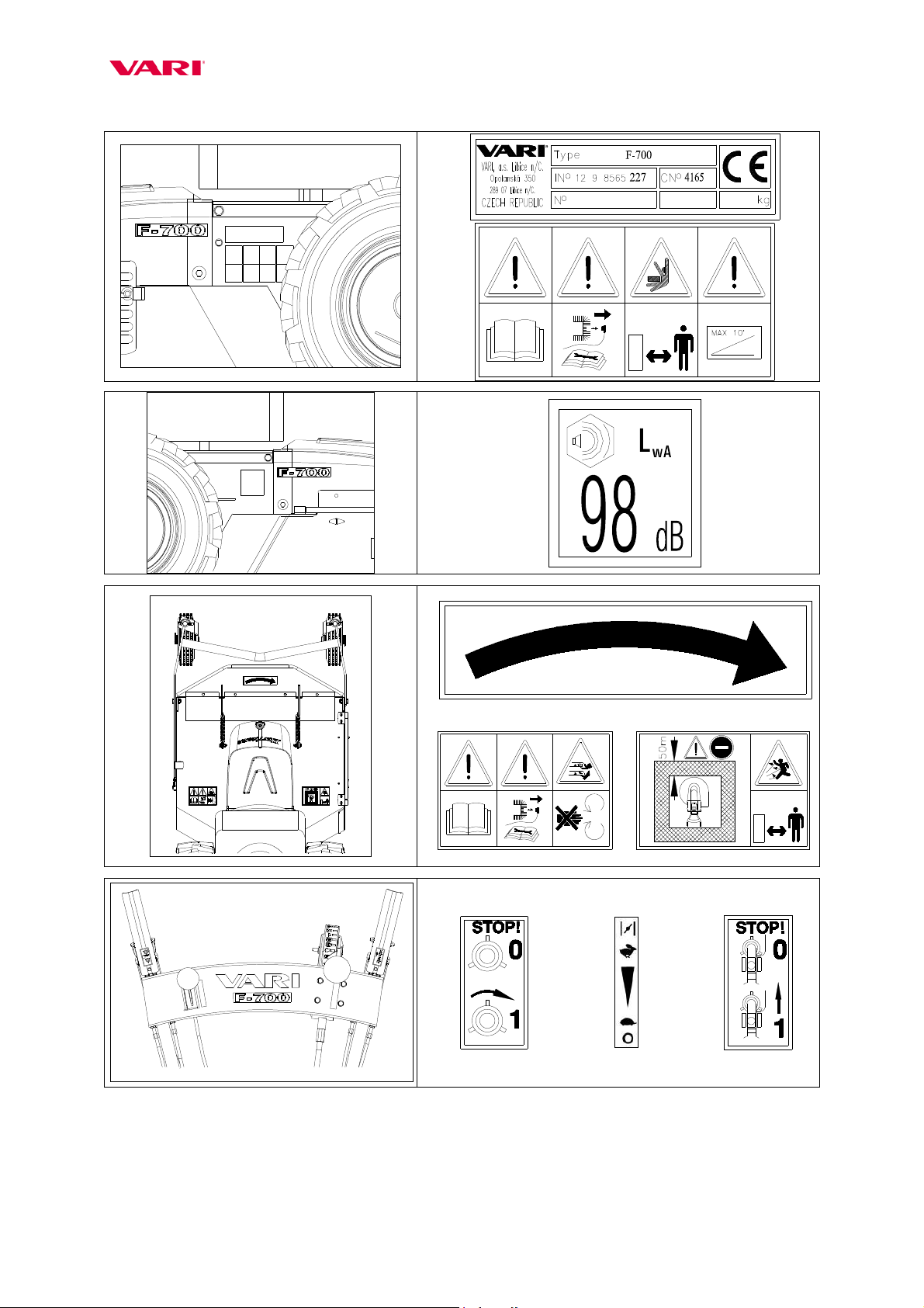
3.3 Safety ictogra hs...................................................................................................... 8
4 Use, technical s ecifications and technical descri tion of the machine .......................... 10
4.1 Machine use.............................................................................................................. 10
4.2 O tional attachments................................................................................................ 10
4.3 Technical s ecifications ........................................................................................... 10
5 Instructions for use........................................................................................................... 11
5.1 Machine assembly.................................................................................................... 11
5.2 Adjustment of handlebars......................................................................................... 13
5.3 Putting into o eration............................................................................................... 14
5.4 Starting the cutting blade.......................................................................................... 14
5.5 Machine travel forward and back............................................................................. 15
5.6 Machine sto ............................................................................................................ 16
5.6.1 Sto ing on the lain........................................................................................ 16
5.6.2 Sto ing on the slo e ....................................................................................... 16
5.7 Working with the machine ....................................................................................... 16
5.7.1 Adjustment of cutting height............................................................................ 17
5.7.2 Travel s eed choice.......................................................................................... 17
5.7.3 The way of stand cutting .................................................................................. 18
5.7.4 Problems at cutting........................................................................................... 18
5.7.5 Cutting on slo es.............................................................................................. 19
5.7.6 Machine trans ort with engine switched off.................................................... 19
5.7.7 Cutting of high grass stands ............................................................................. 20
6 Maintenance, care and storage ......................................................................................... 20
6.1 Machine lubrication.................................................................................................. 20
6.1.1 Gear oil change and re lenishment .................................................................. 20
6.1.2 Engine oil re lacement..................................................................................... 20
6.2 Tightening of bolted connections............................................................................. 21
6.3 Working blade re lacement and shar ening ............................................................ 21
6.4 Re lacement of V-belts and adjustment of tension ulleys ..................................... 22
6.4.1 Re lacement of V-belts.................................................................................... 22
6.4.2 Adjustment of tension ulleys.......................................................................... 23
6.5 Setting u ulley wires, blade brake ........................................................................ 24
6.6 Adjustment of the automatic brake .......................................................................... 25
6.7 The table of service o erations................................................................................. 26
6.8 Diagnostics of driving roblems .............................................................................. 26
6.9 Washing and cleaning of the machine...................................................................... 26
6.10 Machine storage ....................................................................................................... 27
6.11 Dis osal of ackaging and machine after the end of service life............................. 27
7 Instructions for ordering s are arts................................................................................. 27
8 Contact to manufacturer................................................................................................... 28
9 The list of arts................................................................................................................. 28
10 Letter of Guarantee....................................................................................................... 43

F-700
5
1 Basic information
Ask your dealer to provide the machine unpackaging, assembly and brie ing
Fill in the following data concerning your machine. The data are im ortant for ordering
s are arts.
It is advised to have a s are co y of this age with all data on the machine urchase for
the case of loss or theft of the original record.
VARI, a.s. ordering number 4165
Model F-700
Commercial name Hurricane
Engine model Honda GXV 340
Machine ser. no./Year of
manufacture
/
Engine serial no.
Date of delivery (sale)
Su lier
Address
Tel./fax/E-mail/internet
Your notes:
The manufacturer reserves the right of technical modifications and machine innovations that
do not im act the machine function and o eration safety. The changes need not be included in
this Manual.

F-700
6
2 Foreword
Dear customer and user,
Thank you for trusting our roducts. You have become owner of a machine from a wide range
of machines and attachments made by ,a.s. as a system of gardening, farming, small
agricultural and communal technology.
The Hurricane F-700 mulcher is designed to meet the most exacting requirements of
rofessional use. High- erformance engine with a atent- rotected edge on the cutting blade guarantee
a roblem-free mowing of different stand ty es. Mechanical 5-s eed gearbox in combination with
wide travel wheels and low machine centre of gravity enable an easy machine o eration even in the
most difficult terrains. The machine can be equi ed with a snow lough, snow chains and a sulky,
which makes its o eration ossible throughout the whole year. Automatic brake and a ossibility to
lock the front wheels in forward direction rovide for a safe o eration of the machine namely on
slo es.
Please read the Instructions or use care ully. If you follow them ro erly, you will have our
roduct erforming a reliable work for you for years.
2.1 Basic warnings
The user is obliged to get acquainted with the Instructions for use and to follow all instructions
for the machine o eration so that the user’s and other ersons’ health and ro erty cannot suffer any
harm.
Safety instructions contained in this manual do not describe all situations or conditions
ossibly occurring in ractical use. Safety factors such as common sense, diligence and
scru ulousness are not included; it is assumed, however, that all ersons authorized for the machine
o eration or maintenance do ossess the intelligence.
The machine can be o erated only by ersons in good mental and hysical condition. For the
rofessional use of the machine the machine owner is obliged to ensure a work safety training and
rovide instructions on machine control for o erators and to kee records on these trainings and
briefings. Also, the owner is obliged to carry out a so-called categorization o works according to
the relevant national legislation.
Should some instructions in the manual be unintelligible, you are encouraged to contact your
dealer or directly the manufacturer of the machine. The contact address and tele hone/fax connection
are to be found at the end of the manual.
The manual su lied with the machine is an integral art of the machine. It has to be available
at any time, laced at a well accessible lace with no risk of its damage. In the case that the machine
is sold to another erson, the Instructions for use must be given to the new machine owner. If the
above conditions are not met, the manufacturer bears no res onsibility for ossible risks, accidents
and injuries resulting from the machine o eration.
The manufacturer bears no res onsibility for damages caused by unauthorized and incorrect
use of the machine and for damages caused by any machine modifications not authorized by the
manufacturer.
To revent injuries to o erators and other eo le occurring in the vicinity of the machine as
well as damages on ro erty, it is absolutely necessary to follow the safety regulations marked in the
Instructions for use with the following warning safety symbol:
On seeing this symbol in the Manual, read the
ollowing instructions care ully!
Note: Left and right as mentioned in the Manual – is at all times meant as viewed from the
site of the o erator.

F-700
7
3 Operation safety
3.1 Safety regulations
This international safety symbol indicates im ortant messages concerning safety. When
you see the symbol, be aware of a ossible injury threatening to you or to other ersons
and read the following instructions carefully.
The machine o erator must be over 18 years o age. He (she) is obliged to get
acquainted with the instructions for use of the machine and is su osed to be informed
of the general rinci les of work safety.
Prior to carrying out any activities in the near vicinity of the machine, switch the
engine off and wait until the cutting blade sto s moving! Before leaving the machine
alone, switch off the engine!
Never let the engine running at maximum s eed or idling for a long time with the
cutting blade and wheel drive clutches switched off! Com onents of the machine drive
(V-belt, belt ulley, clutch ulley, etc.) might get damaged!
Prior to each employment o the machine, check its arts (working mechanism and
its casing in articular) for a ossible damage or loosening. De ects must be recti ied
without any delay. Re airs are to be made only with the original s are arts.
Before using the machine, the stand to be cut must be cleared of solid bodies such as
stones, wires, loose construction debris, etc., which could be flinging u or which
might damage the machine. If these cannot be removed, don’t work the laces.
The machine is equi ed with a rotating working im lement. Maximum
circumferential s eed is 82 m.sec-1. Therefore, make sure that other ersons move at a
safe distance from the machine when it is in o eration with regard to a ossible flying
away of the cut stand or solid objects!
With res ect to the exceeded recommended values of noise and vibrations, you are
warned to observe the following instructions when working with the machine:
a) Protect your hearing by using suitable rotective aids s ecified in CSN EN
352-1 (shell ear rotectors) or CSN EN 352-2 ( lug ear rotectors). Require
the aids from your dealer.
b) Working with the machine should be interru ted after max. 20 minutes for a
minimum break of 10 minutes. During these breaks, the machine o erator must
not be ex osed to the im act of another source of noise or vibrations.
Machine o erators should use working aids authorized according to CSN EN 166 or
CSN EN 1731 (tight-fitting garments, sturdy shoes, working gloves and rotection
glasses). Kee a safe distance given by the handlebars.
Don’t start the engine in enclosed s aces! Pay increased attention when handling the
machine since the exhaust silencer remains hot after the engine has been switched off;
make sure there are no leakages and s ills on engine arts when refuelling. If they
ha en to occur, dry out the stained arts or wait until the etrol eva orates.

F-700
8
When the machine is in o eration, all other ersons (children in articular) and animals
have to be outside the machine’s working s ace. The machine o erator can continue
working only after they have been shown out to a sa e distance (see Pictogra h 6).
NOTE: The outer safety zone A around the inner working zone B is s ecified in standards EN 12733
and CSN EN 12733. Entry into the working zone is to be revented by using a ro riate rohibitory
signs. Distance between the individual sides of zones A and B must not be less than 50 m. Should the
dangerous zone of machine o eration be entered by a erson or animal, the machine o erator must
release the cutting im lement drive lever without any delay and wait with the further work until the
zone is clear again.
Removal of any rotective equi ment and casings from the machine is forbidden.
The sa e slo e accessibility of the machine is 10°. Maximum inclination of the engine at
work is 20° for a long-time o eration and 30° for a shorter time (u to 1 minute).
NOTE: The machine should be referably not used on wet grass. The terrain you are moving on must
be always safe. Do the work while walking not running. Be articularly careful when changing
direction on the slo e. Cutting on stee ly inclined slo es should be revented. If you fall, do not hold
the machine but release your gri on it.
All kinds of the machine re air, adjustment, lubrication and cleaning are to be made with
the machine switched off and s ark lug cable disconnected.
3.2 Declared noise and vibration values
Hurricane F-700 with engine A B C
HONDA GXV 340 LAeq,T = 89,0+1,0 dB LWA = 98 dB ahv = 2,5+1,3 m.s-2
Ex lanatory notes:
A = declared emission level of acoustic ressure A at o erator’s site L Aeq,T (according to ČSN EN 836+A1/A2,
Attachment H and ČSN EN ISO 11 201)
B = guaranteed level of acoustic erformance of the machine LWA (according to NV No. 9/2002 Gaz.)
C = declared sum of accelerated vibrations transmitted onto o erator’s hands/arms ahv (according to ČSN EN
836+A1/A2, Attachment G and ČSN EN 1033).
3.3 Safety pictographs
The user is obliged to maintain the ictogra hs on the machine legible and to rovide
for their re lacement in the case of damage.
Pictograph No. Sa ety in ormation description
1 Ty e late
2
Instructions for use to be studied rior to machine o eration and maintenance
During the machine maintenance the cable is to be disconnected from the s ark lug
Entry of ex osed and other ersons into the machine’s working s ace is rohibited
Safe slo e accessibility
3 Guaranteed level of machine’s acoustic erformance
4 Arrow for the direction of tool rotation – to the right
5
Instructions for use to be studied rior to machine o eration and maintenance
During the machine maintenance the cable is to be disconnected from the s ark lug
Putting one’s hands or feet into the cutting blade working s ace is rohibited – Danger of
limb cut (off)
6
Entry forbidden for other ersons and animals. Minimum safe distance from the machine.
Danger of injury by flying-off material fragments and flung objects. Other ersons and
animals to be ke t at a safe distance from the machine.
7 Cutting blade drive switch. “0” = blade does not turn, “1” = blade in rotation
8 Lever ositions for adjustment of engine rotations
9 Wheel drive switch. “0” = machine stands still, “1” = machine travels

F-700
9
1
135
2
3
4
5
6
7
8
9

F-700
10
4 Use, technical specifications and technical description
of the machine
4.1 Machine use
This rofessional mulcher is designed for mowing grass stands of all kinds of stalky
grasses, referably old and dry, on both maintained and unke t sites. The mulcher can be used
for cutting self-seeding woody s ecies u to a diameter of 2 cm. Periods most suited for the
machine use are those when the stands are dry and the cutting blades are ca able of crushing
them into small ieces which need not be removed from the surface. The maximum
recommended height of stands emerged in the same eriod when cut is u to 50 cm. This
maximum height may decrease according to stand density, moisture content and ty e.
Cutting width must be at all times accommodated to the density o the cut stand.
With res ect to thread rofile and system of cutting height set-u , the machine is not
designed for ark treatment of green areas.
4.2 Optional attach ents
Snow lough ASR-700, snow chains, braked seat (sulky) AV-700.
Note: The above attachments are sold se arately. Ask your dealer to inform you about the
term of their market introduction.
4.3 Technical specifications
Hurricane
F-700 Unit Value
Length (incl. handlebars) mm 2037
Width mm 744
Height (incl. handlebars) mm 1210
Weight kg 135
Maximum cutting width of the machine cm 68
Cutting blade adjustment height (6 ositions) cm 6-14
Blade s eed (at max. engine revolutions) min-1 2300
Circumferential blade s eed (at max. engine
revolutions, without load) m.s-1 82
Travel s eeds (at max. engine revolutions, without
load) km.h-1 1,53 – 2,32 – 2,94 – 4,07 – 6,75 – R 2,94
Area erformance of the machine (according to stand
ty e) m2/h 1000 – 4400
Engine Unit HONDA GXV 340
Dis lacement cm3 337
Bore x stroke mm 82 x 64
Max. ower at revolutions kW/min-1 8,1/3600 (11 HP)
Max. torque at revolutions N.m/ min-1 24/2500
Max. adjusted engine revolutions min-1 3200 (+/-100)
Fuel tank ca acity litres 2,3
Petrol (unleaded) octane No. 91-95
Oil filling litres 1,1
Oil API SJ/CF (SG/CD)
S ark lug -- NGK BPR5ES
-- BRISK LR17YC

F-700
11
Figure 1: Mulcher Hurricane F-700
5 nstructions for use
5.1 Machine asse bly
Ask your dealer to rovide un ackaging of the machine and briefing in machine
o eration.
With res ect to difficult withdrawal of the machine from the box, it is advised to cut the
box through in corners and then to take off the machine onto a fixed rest. Gri oints: Front:
blade casing edge, Rear: tube of handlebars gri . Regarding the machine weight, work with a
minimum of one other erson.
If you assemble the machine yourself, lease follow the instruction below:
1. Remove all arts from the bag.
2. Cut the lastic ta e holding the shifting lever on the frame of guide wheels. Put the
guide wheels aside. Mount the front lift casing according to Fig. 2 (u er art).
3. Turn the handlebars so that the handrails oint to the rear of the machine. Bowden
cables must not be twisted!
4. Attach the handlebars (1) to the turntable (5) by means of bolt M10x110 with a square
(2), washer ∅10,5 mm (3) and tightening nut M10 (4). Lubricate the thread of the bolt
(2) with grease for hydraulic um s. The tightening nut must be at the right. Fasten
the bowden cables from control levers to the handlebar (at a distance of about 15 cm
from the end of handlebar tube bending) by means of lastic tightening ta es (6).
Accelerator lever
Cutting height adjustment lever
Engine starter gri
Blade casing
Front lift casing
Frame of guide wheels.
Front gri oint
Guide wheels
Travel wheels
with the in
differential
Wheel drive clutch lever
Handlebars
Tightening nut for
adjustment of
handlebars height
Lever for s
ide adjustment
of handlebars
Engine
Lock o
f guide
wheels
Cutting height adjustment
Gear shifting lever
Blade drive lever

F-700
12
5. Fasten the gear shifting lever (7) by means of 3 bolts M6x50 (8), 3 flat washers (9)
and 3 self-locking nuts M6 (10) from the left to the lever holder on the bottom art of
handlebars. The bolt with the washer should be mounted from the right.
6. Hook the s rings (11) into eyes in front casing arms and into holes in footings on the
blade casing with suitable hooks.
7. Screw the guide wheels on the lugs in the front of blade casing by means of bolt (12),
flat washer 10,5 mm (13) and self-locking nut M10 (14). When utting the frame of
guide wheels into the lock- late guiding, the locking in must be ushed in (by
ressing the locking lever of cutting height adjustment on the right handlebar gri –
see Fig. 1).
8. Mount the bum er according to Fig. 2 (lower art).
Figure 2: Machine assembly
Front casing assembly
Unscrew the front casing from the machine chassis (on
both sides).
Put the front casing through the cut outs in the chassis
deflector (when lifted, the front casing must sto
against the deflector) and screw it back to the machine
chassis – tighten the nuts, so that the casing can be
freely lifted.

F-700
13
Bum er assembly
Unscrew 4 bolts M8x20 holding the handlebars holder
on the machine chassis.
Put the bum er on the handlebars holder and screw the
bolts M8x20 back. The bowden cable of brake must
lead between the machine chassis and the bum er.
5.2 Adjust ent of handlebars
Handlebars can be adjusted in two lanes:
• Height: Loosen tightening nut M10 ( osition (1) in Fig. 3) and do the adjustment of
handlebar gri s at height comfortable for the o erator.
• To sides: Press down the lever ( osition (2) in Fig. 3) and turn the handlebars by one
osition to the left or to the right.
6.
Plastic ta e
4
Tightening nut
11
S ring (2 cs)
3
Washer
12
Bolt
13
Flat washer
14
Self-locking nut
1
Handlebars
2
Bolt
5
Turntable
7
Gear
shifting
lever
8
Bolt
9
Washer
10
Nut

F-700
14
In order to lessen the machine size e.g. for trans ort in a car, the handlebars should be either
tilted forward over the engine or lowered into horizontal osition and then turned clockwise
by 180°. Bowden cables must be watched not to get tensioned somewhere on the machine
construction.
Figure 3: Adjustment o handlebars
5.3 Putting into operation
The machine may be delivered without engine illings (in dependence on di erent
national regulations)!
First thoroughly read the instructions or engine use. You can prevent a possible
damage to the engine.
1. Check oil volume in the engine and/or fill the engine with the rescribed oil grade and
volume. Fill the tank with the rescribed amount and ty e of etrol.
2. Move the accelerator lever into the front osition („CHOKE“). Start the engine by
ulling on the manual starter (instructions for starting see instructions for engine use).
3. Let the new or cold engine running on choke for about 30 seconds (accelerator lever in the
„CHOKE“ osition), then move the accelerator lever into the osition „MAX“. In this
osition let the engine running for about 30 seconds.
Do not leave the machine alone when doing this!
5.4 Starting the cutting blade
When starting the engine, the two levers on the handlebars must be in the o
position.
1. Start the engine while adhering to instructions resented in the o erating manual for
engine use.
2. Set-u maximum engine revolutions by using the accelerator lever on the right handrail.
(Should the engine be cold, let it warm u at maximum revolutions for about 1 minute).
3. Gras the left handlebar gri with your left hand. Then slowly ress the cutting blade
drive clutch lever on the right handlebar gri with your right hand.
Press the lever slowly up to about two thirds o the stroke so that the cutting blade
can start rotating and the engine does not stall.
1
Tightening nut
for height
adjustment of
handlebars
Lubrication oint
2
Side
arrestment
lever

F-700
15
Starting of the cutting blade is accom anied with a artial V-belt sli age and with the
accom anying henomena such as whistling, rattling, etc. The henomenon usually
disa ears after the belt has run in.
4. After the cutting blade starts turning, ress the lever com letely to the handrail and hold it
firm.
Note: If the blade drive is re eatedly switched on during cutting, engine stalling may occur due to
resistance of grass biomass in the s ace of blade casing. This s ace must be - if ossible - always
ro erly em tied when starting the blade drive (see oint 5.7.4).
In a new or cold engine, a few of the cutting disk starts may result in engine stalling. The
henomenon will disa ear after the engine warms u . If the blade drive cannot be started even after
the engine has got warm, follow the table resented in Cha ter 6.8 for diagnostics.
5.5 Machine travel forward and back
Machine travel orward and back is controlled by the upper red sheet-iron lever on
the le t gri of the handlebars.
• Travel orward: Shift into one of gears (1 - 5) by using the gear shifting level. Then ress
the u er red sheet-iron lever on the left handrail com letely down to the gri and the
machine will start moving forward (sometimes with a little delay due to the run-out of the
in differential in wheels). Start walking simultaneously with the machine start, ada ting
your walk ace to the direction and s eed of the machine.
Be prepared that the machine can start moving with a little jerk.
Starting the machine on the 5th gear, let the machine start moving at about ½ o the
maximum engine speed. A ter the machine gets moving, set up an engine speed
convenient to the pace o your sa e walking.
• Travel back: Shift the gear shifting level to the „R“ osition. Then ress the u er red
sheet-iron lever on the left handrail down to the gri and the machine starts moving in
reverse direction (sometimes with a little delay due to the run-out of the in differential in
wheels). Simultaneously with the machine start you have to start walking in the
corres onding direction and at a corres onding ace.
Be very care ul when backing with the machine!
Figure 4: Handlebars and control levers
Positions of engine s eed set-u
lever
STOP MIN
MAX CHOKE
Blade drive clutch and brake lever
Accelerator lever (engine s eed adjustment)
Guide wheels adjustment lever (cutting height)
Gear shifting lever
Lever of wheel
drive clutch
and
automatic brake

F-700
16
Note: All four main ositions of engine s eed adjustment lever are arrested by means of a
sim le system (stam / rojection) in the lever body.
5.6 Machine stop
5.6.1 Stopping on the plain
If you wish to sto the machine travel, release the lever on the left handlebar gri . The
machine will sto moving but the blade will still turn. The cutting blade drive will be
switched off immediately after release of the lever on the right handlebar gri . The blade will
be sto ed by the safety brake.
Prior to carrying out any activities in the near vicinity o the machine, switch o the
engine and wait until the cutting blade stops! Always switch the engine o be ore
leaving the machine!
Never let the engine running at maximum speed or idling with the cutting blade
drive clutch released and with the released clutch o wheel drive or a long time!
Machine drive components (V-belt, belt pulley, clutch pulley, etc.) might su er a
damage!
If you wish to switch the engine off, do it by shifting the lever to the „STOP" osition.
In the case o any critical situation, release your hold on the handlebars without any
delay. Do not hold on the machine! The levers will return to their zero position, the
machine and the cutting blade will stop (while the engine is still running at set-up
revolutions; this is why it is to be switched o by shi ting the lever to the „STOP“
position as soon as possible!)
5.6.2 Stopping on the slope
The machine is equi ed with an automatic brake which - if ro erly adjusted - will
safely ut the machine to sto on a slo e u to 30°. The automatic brake is ut into o eration
after releasing the wheel drive clutch lever on the left handlebar.
Never let the engine running at maximum speed or idling with the cutting blade
drive clutch released and with the released clutch o wheel drive or a long time!
Machine drive components (V-belt, belt pulley, clutch pulley, etc.) might su er a
damage!
5.7 Working with the achine
Prior to the machine use, the stand must be cleared o solid bodies such as stones,
wires, loose construction debris, etc., which could be lung or might damage the
machine. Should these be impossible to remove, working o the places should be
avoided.
Cutting width has to be at all times accommodated to stand density!
I possible, do not use the machine on wet grass. Remember that the terrain you are
moving on must always be sa e. Walk (never run) at work. Be care ul especially
when changing the machine direction on slopes. Do not cut on steep slopes. When
accidentally alling, immediately release your hold on the machine.

F-700
17
5.7.1 Adjustment o cutting height
Adjustment of cutting height is affected by several im ortant factors:
• stand height and density
• lant s ecies revailing in the stand
• machine travel s eed
• cutting width
• surface unevenness
There is a general rule that the higher value of above mentioned factors, the greater height
of guide wheels and cutting blade height adjustment above the surface. The cutting height
should revent overfilling of the blade working s ace as such a situation reduces the blade
s eed, the engine cannot work at o timum revolutions and the self-cleaning ca acity of
cutting blade s ace from accumulated grass biomass is im aired.
Prior to working a terrain irregularity, increase at all times the cutting height to the
very maximum. In this way you will prevent a blade damage.
Cutting height adjustment by means of guide wheels:
a) ush on both handrails so that the arresting in in the arresting late is released;
b) ress the black lastic lever of cutting height adjustment on the bottom side of the
right handlebar gri with fingers of your right hand (see Fig. 4);
c) reduce or increase the height of guide wheels adjustment by ushing on the two
handrails;
d) adjust one of oval holes on the arresting late against the arresting in;
e) release the lever.
Figure 5: Cutting height adjustment
5.7.2 Travel speed choice
The adjustment of machine travel s eed is ruled by similar factors as the adjustment of
cutting height. The main rinci le dictates that the greater is the stand density or height, the
lower is the machine travel s eed. Gears are chosen by gear shifting lever situated on the left
(as viewed from the o erator’s site) on the handlebars diagonal. The shifted gear is indicated
by an arrow on the lever against the adjustment line at the gear number on the scale.
Gears should be shi ted only with the wheel drive clutch released. Never change the
gear when the machine is moving!
Position of the greatest
cutting height
Position of the
lowest cutting
height
Arresting in,
lubrication
oint

F-700
18
Figure 6: Travel speed choice
Maximum speed. Meant
exclusively for the machine
trans ortation.
4
Maximum working speed.
Low-height or low-density
stand. Good for flat and even
terrains.
3
2
Medium working speed.
Medium-height and high-density
stands. Good for mild slo es.
1
Minimum working speed.
High and high-density stands.
Good for stee slo es. Cutting of
brushes and self-seeded woody
s ecies.
N
Neutral gear. Engine starting.
Machine trans ortation with
engine switched off.
R
Reverse gear.
5.7.3 The way o stand cutting
Set the engine on the maximum s eed, let the cutting blade rotate at the maximum
s eed and then get the machine into motion, facing the to-be-cut stand.
At cutting, you should roceed only in such a way that the to-be-cut stand is - if
ossible - on the left side of the machine. When cutting on slo es, it is advised to drive the
machine along the slo e contours. Watch a maximum ermissible long-term machine
inclination of 20° (30° over a short-term – u to 30 sec)!
If the cut stand is very dense, grown through, rotten from below or lodged, the
machine cutting width must be accordingly reduced, greater cutting height adjusted or
machine travel s eed reduced so that the cutting blade rotations are not excessively slowed-
down, which would result in the im aired cutting quality and engine overloading.
5.7.4 Problems at cutting
Choking of the s ace under the cutting blade cover with the grass biomass shows in:
a) Engine markedly losing speed but not stalling: wheel drive to be switched off
immediately (lever on the left handrail gri ); the machine front to be slightly lifted by
ushing down on handrails. Then shift in reverse gear (R) and slightly back with the
machine. The s ace under the cutting blade cover will do itself a artial clearance
from excessive grass. Then drive the machine against the stand again.
b) Engine losing rotations and stalling: release both levers on the handlebars, start the
engine, shift in reverse gear and back with the machine out from the stand to be cut.
Switch off the engine. Clean the s ace under the cutting blade cover and s read the cut
grass across the ground surface. Start the engine, switch on the cutting blade drive and
drive the machine against the stand again.
Be very care ul while li ting the machine and driving on reverse gear!
Gear change
lever.
Arrow
Wheel drive
clutch lever
Gear scale

F-700
19
Tilt the machine always only backwards onto the handlebars. Be very care ul while
moving under the li ted machine! Secure the machine against its spontaneous
motion!
Be very care ul while cleaning the space under the cutting blade cover. Cutting
edges o the blades are sharp. You should wear protective gloves or use a suitable
piece o branch etc.
5.7.5 Cutting on slopes
I possible, do not use the machine on wet grass. Remember that the terrain you are
moving on must always be sa e. Walk (never run) at work. Be care ul especially
when changing the machine direction on slopes. Do not cut grass on steep slopes.
When accidentally alling, immediately release your hold on the machine.
The sa e slope accessibility o the machine is 10°.
For a better steering control of the machine secure the guide wheels with locking ins in
straight direction. The ins are included in machine accessories. If not to be used, they should
be folded between lugs on the handrail tube. Use medium or minimum travel s eed.
For cutting on slo es u to do 20° it is recommended to drive the machine along the
contour. It is the safest movement on the slo e. It is also ossible to make use of the side
adjustment of handlebars.
On slo es between 20° and 30° never drive the machine in the downhill direction for a
long time. Engine oil filling level moves out of sucking oints and the engine oiling is
irregular and insufficient.
Figure 7: Arrestment o guide wheels on the slope
5.7.6 Machine transport with engine switched o
For the machine trans ort with engine switched off - when you ush the machine - make
use of a ossibility to unlock the in differential in wheels. Thus, the wheels can freely rotate
around the axle and the machine can be easily ushed forward.
Pull the in artly out and turn it by 90°.
Figure 8: Unlocking o the di erential
The automatic parking brake is out o
operation a ter unlocking the di erential!
This is why you are advised to unlock the
di erential at all times only on the plain!
When trans orting the machine with engine
switched off on slo es, shift in neutral gear („N“) and
ress the travel clutch lever on the left handrail. The
automatic brake will be unblocked and the machine
can be ushed manually.
Lubrication oint
Lubrication oint
Lubrication oint

F-700
20
5.7.7 Cutting o high grass stands
This machine can also be used for cutting high grass stands without crushing. Herbage can
be then used both for drying and as green fodder.
Note: with res ect to the cutting method, the ro ortion of crushed lants is higher than in other
methods more friendly to lants.
Instructions for assembly and use are enclosed in the ackage of side refuse casing.
6 Maintenance, care and storage
To ensure a long-term satisfaction with our roduct, it must be given ro er care and
maintenance. Regular maintenance of the machine will revent its early wear roviding at the same
time for a correct functioning of all its arts.
Prior to any machine use, check all bolts and nuts for their correct tightening. Make sure that all
safety devices are in good order. Check the blade, res ective bolts and individual elements of cutting
mechanism for a ossible wear or damage. In order to kee a good balance of the machine, worn-out
or damaged blade and res ective bolts should be re laced with original s are arts. All worn-out or
damaged com onents should be re laced also for the reason of machine safety. Oil level in 4-stroke
engines must range within limits described in the “Instructions for engine o eration and
maintenance“.
Follow all instructions concerning the intervals of machine maintenance and adjustments. It is
advised that you kee records on the number of machine working hours and on the conditions in
which the machine was working (for service ur oses). Similarly as the current maintenance also the
after-season maintenance of the machine should be entrusted to one of our authorized service
worksho s in the case that you do not trust your own technical skills.
Regarding the machine weight, all maintenance and adjustment procedures are to
be done by two persons.
6.1 Machine lubrication
6.1.1 Gear oil change and replenishment
Gearbox has ermanent oil filling for the entire service life of the machine.
6.1.2 Engine oil replacement
Information is to be found in the Instructions for engine o eration and maintenance.
Engine oil available on the Czech market and s ecially designed for air-cooled engines of
gardening machines is MOGUL FORTE ALFA.
When replacing oils, ollow the basic hygienic principles and regulations and laws
on environment protection.
Table o machine lubrication
Machine lubrication During
season
A ter
season Lubricant Figure no.
All wires on the in ut to Bowden cables a
nd on
the out ut from adjustment bolts
min 2x
yes
silicone oil in atomizer -
Wheel in and fork in on the guide wheel hinge
min 1x weekly
yes grease, engine oil 7
Contact area of handlebars with the holder of
handlebars min 2x yes grease 3
Detent in of guide wheels min 1x weekly
yes grease 5
Arm in of tension ulleys, gear shifting lever on
the gearbox min 2x yes grease, engine oil 9
Brake lever seating near the front belt ulley
(after disassembling the lastic cover of the belt) min 2x yes engine oil 9
Table of contents
Other Vari Lawn And Garden Equipment manuals