6
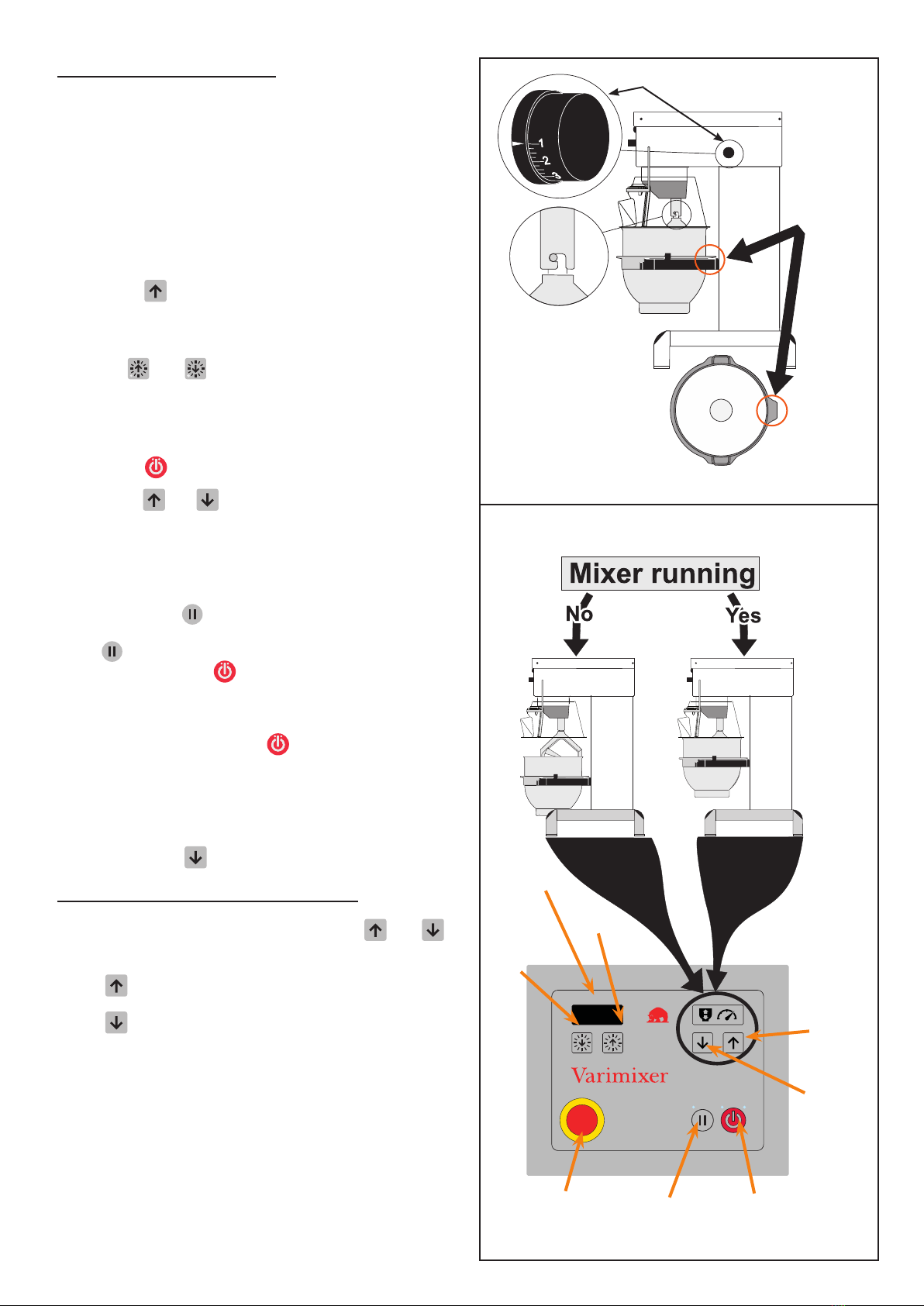
start-up after stop at hIGh speed:
If the emergency stop is activated or the safety guard
has been opened while lifting or lowering the bowl...
• Release the emergency stop (g. 3) by turning it
anticlockwise or close the safety guard.
• Lifting/lowering of the bowl can be reactivated.
If the emergency stop is activated or the safety guard
has been opened while the mixer is running, and you
do not want to start up at the same speed...
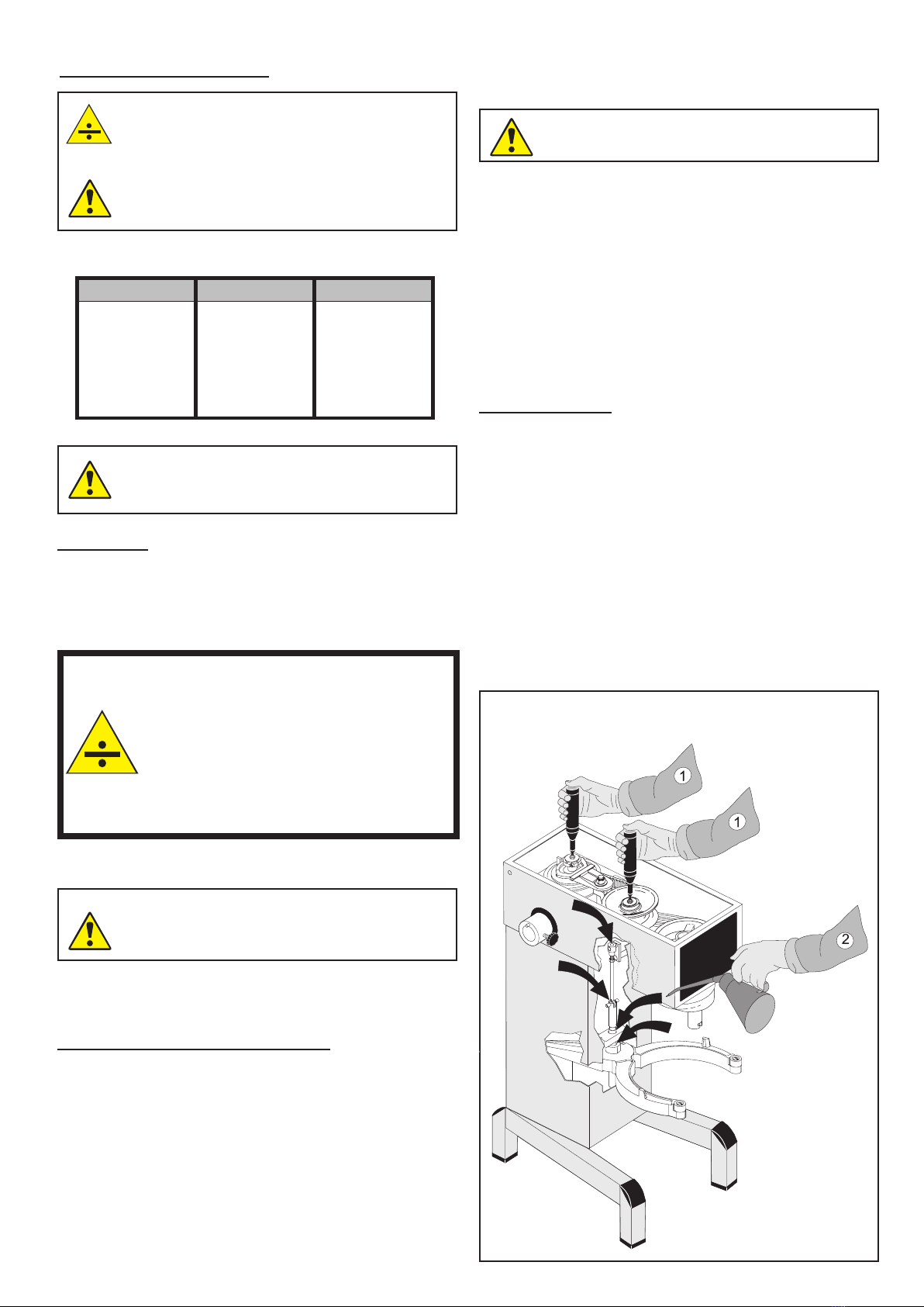
• First lower the bowl: Start with releasing the emer-
gency stop or close the safety guard. Then take the
lid off the mixer and press the small red button on
the top side of the control panel while simultaneously
pressing .
• Take the tool out of the bayonet.
•
Close the safety guard, move the bowl arms up to the
top position (empty or with the bowl), start the mixer
and run again to the lowest speed by pressing .
• Stop the machine and secure the mixer’s lid again.
The mixer can now be operated normally.
If the emergency stop is activated or the safety guard
has been opened while the mixer is running at low
speed, and you want to start up at the same speed...
• Release the emergency stop (g. 3) by turning it
anticlockwise or close the safety guard.
• Press and the machine will start at the speed it
was stopped at. The speed can now be regulated
using and
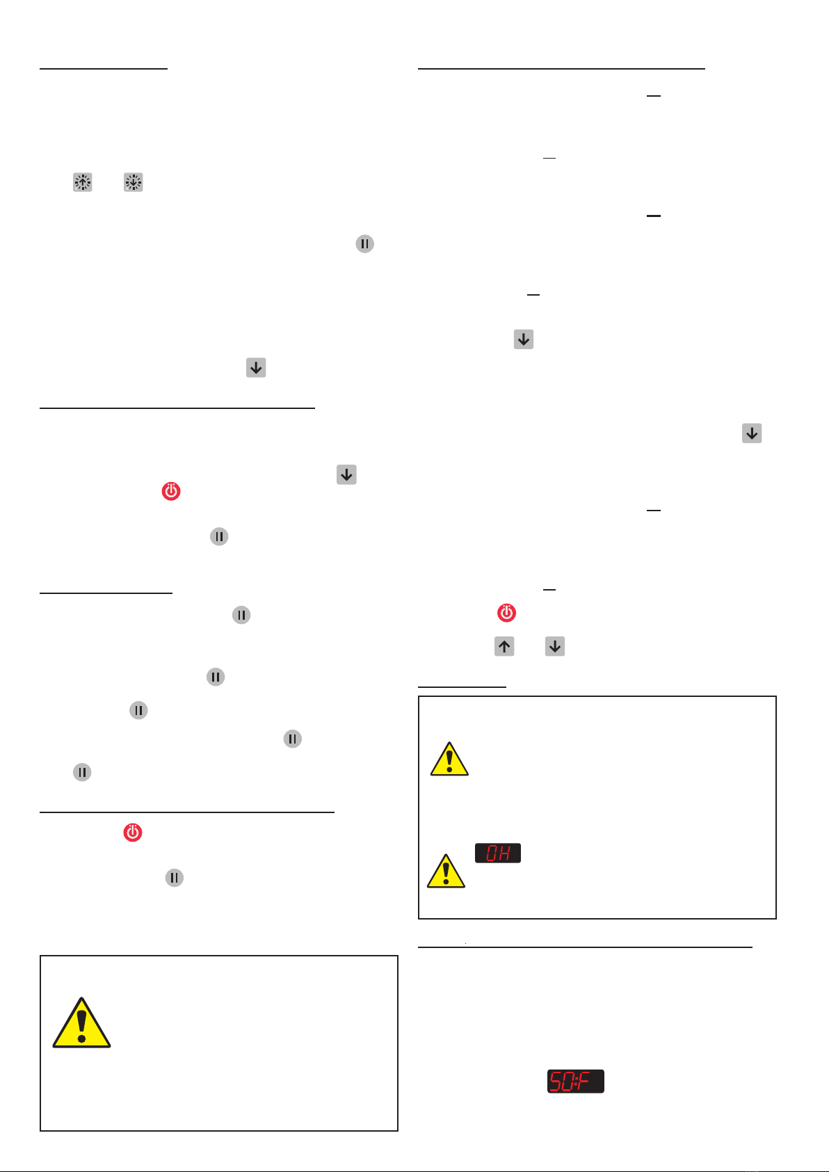
overload:
The mixer must not be overloaded. Sticky and
heavy doughs can overload the mixer.
The overload is further exacerbated if the mixer
tool’s speed is set above the recommended
amount or if the wrong mixer tool is used. Larger
lumps of fat or chilled ingredients must be re-
duced before they are put into the bowl.
Longer time overload will interrupt the mixer.
will be written in the mixer’s display. After
a short while the display will change back to normal
modeandyoucanstartthemixeragain asdescribed
in “Start-up after stop at high speed”.
software versIon of the Control panel:
• When you turn on the mixer (power is connected to
the mixer or the emergency stop is released), the
control panel software version can be read on the
mixer’s display:
• It rst displays how many times power has been con-
nected to the mixer.
• It then displays .
• Then it displays the software version.
tImer funCtIon:
The mixer has an optional timer function. If no time is set
on the timer, the display will instead show the time the
mixer has run for.
• The timer can be set to a maximum of 60 minutes.
• and can be used to set the time before start-
ing the mixer or while the mixer is running. The time
can be changed after it has been set.
• When the timer is in use it is important to use to
stop and start the mixer if you do not want the timer
to be reset.
• When the time runs out the speed will be reduced to
a minimum and the mixer will stop.
• You can select automatic bowl lowering when the
timer is in use. Briey press .
automatIC lowerInG of the Bowl:
• If the timer is in use, the bowl can automatically be low-
ered when the time runs out and the mixer stops.
• While the mixer is running, briey press , The
green LED by will ash until the mixer stops.
• When automatic lowering of the bowl is selected it is
important that you use to stop and start the mixer,
otherwise the selection will be reset.
pause funCtIon:
The mixer has a pause button , which should be used
to stop and start the mixer in a process where the timer
is used.
• Stop the mixer using . The timer will continue to
count downwards when you start the mixer again by
pressing .
• When you stop the mixer pressing you can lower
the bowl and open the safety guard. When you press
again, the timer continues to count downwards.
the mIxer’sstart speed after stop:
Stop using : The mixer’s speed is reduced to lowest
speed and will start at the lowest speed
Stop by pressing : The mixer’s speed is reduced to
lowest speed and will start at the lowest speed.
Stop using timer runout: The mixer’s speed is reduced
to lowest speed and will start at the lowest speed.
Stop using emergency stop: The mixer
will start at the speed it was stopped at.
Emergency stop must only be used in
emergencies.
Stopbyopeningthe safety guard: The mixer
will start at the speed it was stopped at.
The safety guard must not be used to stop
the machine!