Variobot tinobo-Steuereinheit User manual

Analog control unit for mobile robots
Soldering kit for experimentation
For Fischertechnik Mini Bots and
other Robots (till 80 mA, for higher
output-currents please contact us)
Most diverse functions
Requires no programming
Patented sensor technology

Summary
We are pleased that you have decided for this
high-quality soldering kit for mobile robots. It
opens up a new and exciting access to analog
amplifier circuits. You will certainly have fun
and experience various possibilities to experi-
ment and tinker about for a long time.
This control unit gains its “sensory impressions”
with the help of light sensitive sensors. With the
patented combination of sensors, your robot can
navigate precisely and react sensitively to its
environment.
The “brain cells” of the circuit board consist of
four operational amplifiers. They control the
motors and can be wired variably with resistors,
capacitors, or diodes via numerous slots.
The unit is capable of a lot:
Surprising driving maneuvers through
sensitive reaction to light and shadow
Avoiding obstacles and collisions
Following dark or bright lines
Following different objects
Remote controlling via flashlight
Interaction with other robots via infra-
red light
Combination of different functions
The control circuit

Components overview
1 red control board
1 vertical switch (S2)
5 photo transistors (T1, T2, T3, T4, T5)
6 IR-LEDs (IR1R - IR3R, IR1L - IR3L)
4 red LEDs 5 mm (L1R, L2R, L1L, L2L)
2 white LED-holders
1 black electrical tape
1 shrink hose (3.2 mm)
1 assortment box
4 diodes
2 dual operational amplifiers (IC1,IC2)
2 potentiometers 10 MΩ(P1, P2)
10 resistance bridges 0 Ω
1 resistor 4.7 Ω
1 resistor 10 Ω
2 resistors 47 Ω
6 resistors 1 MΩ
6 resistors 2.2 MΩ
6 resistors 4.7 MΩ
6 resistors 10 MΩ
12 sockets 2-pin
2 sockets 3-pin
4 IC-sockets 6-pin
6 IC-sockets 8-pin
4 IC-sockets 14-pin
2 capacitors 10 nF
2 capacitors 22 nF
2 capacitors 47 nF
2 capacitors 100 nF
2 capacitors 220 nF


Note:
IC1 includes the two operational amplifiers OP1R and OP1L (triangular circuit symbols). IC2 includes
OP2R and OP2L. In this application each motor is controlled by two operational amplifiers.
4. Insert two 3-pin and two 2-pin sockets at the
indicated locations on the back of the board
and solder them on the top.
5. The 5 photo transistors (light sensors) have a
transparent housing with a red marker and
legs of different lengths. The curved lenses
must be looking outward. Solder three of
these photo transistors T1, T3, and T5 at the
corresponding markings.
6. Solder the wires for the power supply and the
motors on the back of the board. Pay atten-
tion to correct polarity.
Note:
To move forward, the voltage at MR1 (red plug)
has to be higher than at MR2 (green plug) and
the voltage at ML1 (green) has to be lower
than at ML2 (red).

Preparation and first commissioning
1. Build your Fischertechnik bot e.g. as shown in
the picture or use a different robot platform.
2. Shorten the pins of the remaining two photo
transistors T2 and T4 (red marking) according
to the illustration. Solder a piece of wire to
each of them. Pay attention to correct polari-
ty (C -> red / E -> green). Solder the other
end of the wires to a 2-pin socket.
Adapt your Mini Bot in order to fix the control
unit. Connect the plugs for the motors.
Finally plug these sockets into the 3-pin sockets
of the control board ensuring that the contacts
located towards the center of the board remain
free and that the curved lenses of the sensors
are directed forward. When installing the sen-
sors, the contacts must not touch. Alternatively
you can use the photo transistors from fischer-
technik.

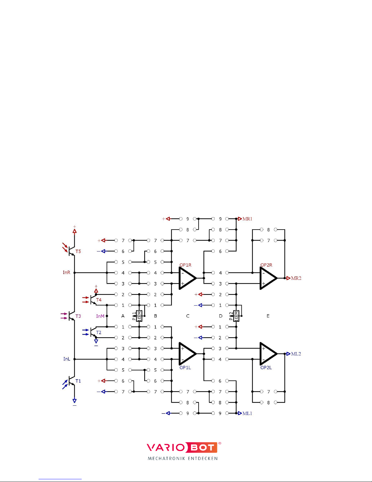
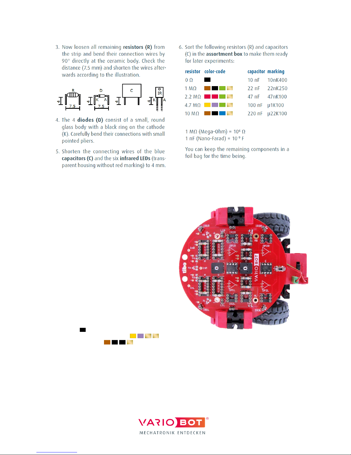
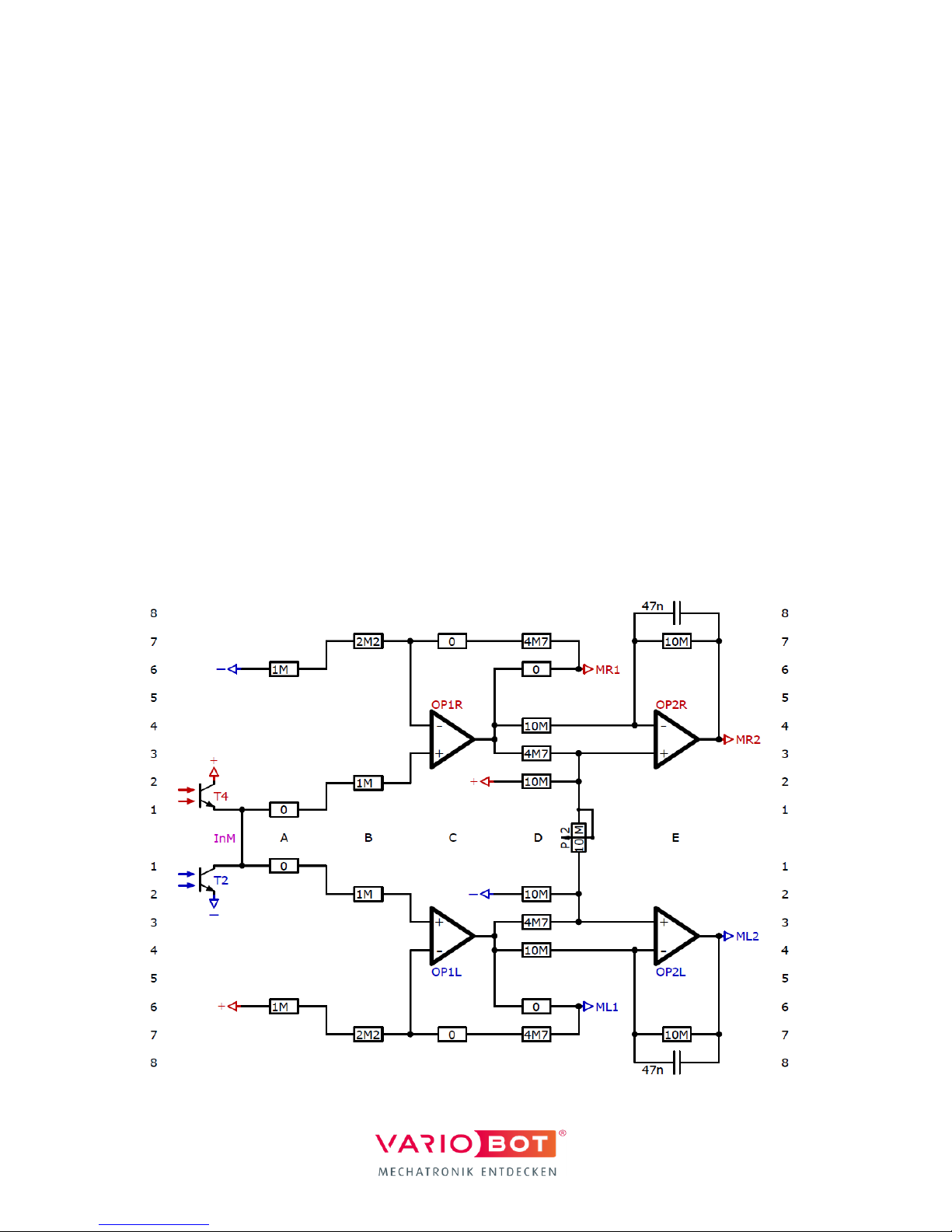
7. The test circuit shown in the illustration al-
lows you to adjust the maximum speed of
the motors via a series resistor if necessary.
For this adjustment, the operational amplifi-
ers OP1R and OP1L are set to maximum gain.
Use the 14-pin sockets to connect the [+] and
[–] inputs of the OPs according to the illustra-
tion, each via a 1 MΩ resistor and a 0 Ω re-
sistance bridge to the supply voltage (square
solder pads with [+] or [–] marking). Then use
the 8-pin sockets to connect the [+] and [–]
inputs of OP2R and OP2L, each via a 10 MΩ
resistor to the supply voltage or the output of
OP1R and OP1L.
8. Initially, connect both motor connections MR1
and ML1 directly via a 0 Ω resistance bridge
with the outputs of OP1R and OP1L according
to the illustration. Now turn on your robot. If
it drives in a slight curve, replace the 0 Ω
bridge before the faster of the two mo-
tors with the 4.7 Ω resistor or
the 10 Ω resistor , ensuring the
robot drives in a line as straight as possible.
The installed resistor then stays in place for
all circuits.
Note:
The right motor rotates forward if the voltage at
the [–] input of OP1R is lower than at the [+]
input. The left motor, however, rotates forward
if the voltage at the [–] input of OP1L is higher
than at the [+] input. OP2R and OP2L invert the
output signals of OP1R and OP1L to let the mo-
tors rotate in both directions with full speed.

Short introduction to the operational amplifier
An operational amplifier (OP) has a [–] input, a
[+] input, an output, as well as two connections
[+/–] for the power supply.
It amplifies the voltage difference between the
[+] input and the [–] input. However, as this
amplification is far too high for most applica-
tions, a resistor R1 is installed before the [–]
input and the output signal Out is returned to
the [–] input via another resistor R2.
Via this feedback, the amplifier controls the
output Out to align the voltage at the [–] input
with the voltage at the [+] input.
The supply voltage in the diagram is U = 9 V.
The signals of the circuit (In+, In–, and Out) are
displayed as voltage arrows relative to 0 V and
are connected via the red bar. For example,
input voltages In–= 6 V and In+ = 5 V result in
output voltage Out = 3 V. The horizontal position
of the arrow In+ is determined by the ratio of
the resistors R2/R1 (2MΩ/1MΩ) and determines
the amplification A, which is the ratio between
the change of Out and the change of In–or In+.
a) If e.g., In–is increased by 1 V (and In+ re-
mains constant), Out decreases by 2 V. In this
case, this results in a negative amplification A =
–R2/R1 = –2. You will use this connection for the
“light follower” in the following.
b) However, if In–remains constant and In+ is
increased by 1 V instead, Out increases by 3 V.
The amplification A = 1+R2/R1 = 3 is now posi-
tive. You will use this connection later for the
“line follower”.
Note:
For more information about the functionality of
the control unit please also read the manual of
the tibo robot kit at:
variobot.com/downloads

How to build a light follower
This circuit enables your robot to navigate au-
tonomously with the help of the three sensors
T1, T3, and T5. The two sensor signals InR and
InL control the motors via OP1R or OP1L. OP2R
and OP2L invert these two signals after a short
delay (depending on the 220 nF capacitors) in
order to change the direction of the motors. As
the group of sensors always responds to relative
lighting conditions, the control unit can navigate
in variable lighting without having to send out
light by itself.
1. Adapt the circuit according to the wiring dia-
gram. (2M2 signifies 2.2 MΩ, 220n signifies
the two 220 nF capacitors). For simple orien-
tation, all slots are marked by letters from A
to E and numbers from 1 to 8. Ensure that the
components are connected by the traces on
the circuit board according to the diagram.
2. Set the potentiometer P1 to center position at
5 MΩ and potentiometer P2 to left position at
0 MΩ with a small screwdriver.
3. Turn on your robot and observe how it be-
haves. Adjust the relative incidence of light
on the sensors with some fischertechnik parts
if necessary.
If the robot e.g., mostly turns to the right (the
right motor rotates backwards), the right sensor
T5 is receiving too much light. Cover T5 a little
bit. If the robot does not move forward at all
even though his path is free, screen both T1 and
T5 from the light a little more. But not too
much! Otherwise, the robot will be blind.
4. Now observe how it reacts to light and obsta-
cles. What roles do the brightness and the
size of the obstacles play? What influence
does the potentiometer P1 have?
If the resistance of P1 is reduced (potentiometer
turned to the left), the robot tends to move
backwards or to change direction. If P1 is in-
creased, it rather moves forwards and maybe is
not able to turn on the spot.
5. Test different amplifications and damping by
varying the resistors R(D7) and the capacitors
C(D8) or C(E7).

How to build a line follower
With this circuit, you can let your robot follow a
dark or bright line. The serially wired sensors T2
and T4 supply the voltage signal InM, which
controls the motors via OP1R and OP1L.
1. Adapt the control circuit according to the
wiring diagram. Set the potentiometer P2 to
left position at 0 MΩ for maximum speed.
2. Use a bright surface with consistent and
sufficiently strong lighting from above. Make
sure that no direct light influences the sen-
sors T2 and T4.
3. Tape a desired lane on the surface with the
black electrical tape.
4. Place the robot on the line and off it goes!
5. If the robot does not drive in the middle of
the lane, you can adjust T2 and T4. If it
drives e.g., too far on the right of the lane or
even strays from it completely, the left sen-
sor T2 is getting too much light. Screen it a
little from the light by shifting the red 5 mm
building block above.
6. Use P2 to adjust the speed of your robot.
7. Test how the robot behaves when confront-
ed with lines of different widths, intersec-
tions, or even branching.
8. Test different amplifications and damping by
varying the resistors R(A6), R(B7), R(D7), or
the capacitors C(E8).
9. The two additional 4.7 MΩresistors R(D3)
effect a speed reduction of both motors,
when the robot has to change its direction.
Test how it works without them or change
its value.
10.Let the robot push small dark objects ahead
of him instead of letting him follow lines.
11.Place the sensors T2 and T4 on the inner
slots of the corresponding 3-pin socket to
make it follow a bright line (e.g., a strip of
paper) on a dark background.

Popular Toy manuals by other brands

Dynacraft
Dynacraft Hello Kitty owner's manual

VTech Baby
VTech Baby Cuddle & Sing Elephant instruction manual

Mega Bloks
Mega Bloks Call of Duty DPW87 instructions

MELINERA
MELINERA 288594 Operation and safety notes

HobbyZone
HobbyZone Firebird DeltaRay instruction manual

Mattel
Mattel Barbie Dreamtopia FTV98 instructions