VARIOVISION WVS-16 User manual

Welding camera system WVS-16
By semiautomatic or automatic welding equipment the service and control of the welding torch
mostly occurs from a control station. To set the position of the welding torch and the
parameters for the welding process optimally, however, a visual inspection from the control
station is required.
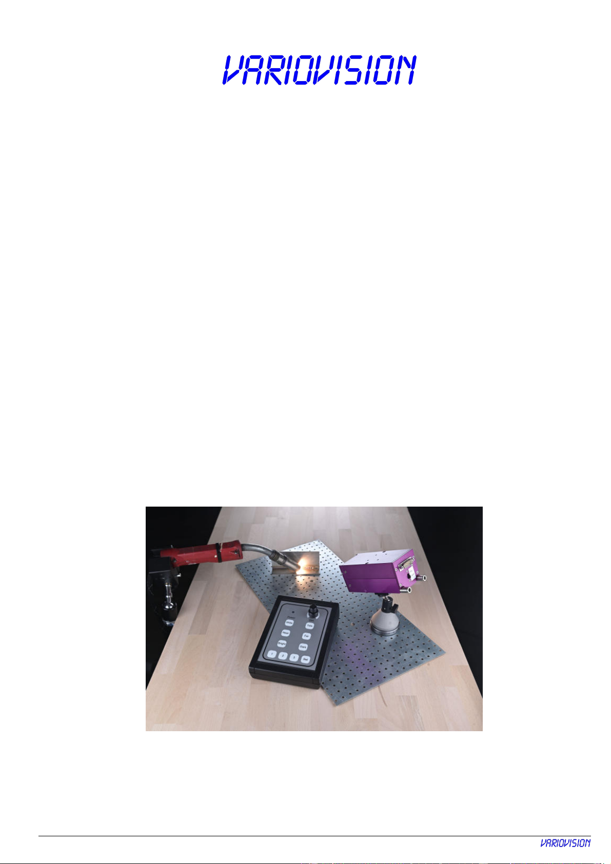
The welding camera WVS-1 provides a sharp colour picture and allows therefore an optimal
observation of welding torch, filler wire and work piece as well as welding arc and melting
area. Zoom, sharpness and brightness can be fast and simply adjusted via a small operating
panel - before, during and after the welding process. This can help you e.g., to shorten the
setup time substantially or faster recogniton of possible welding mistakes.
Two storage buttons can be overwritten with new settings by the user at any time.
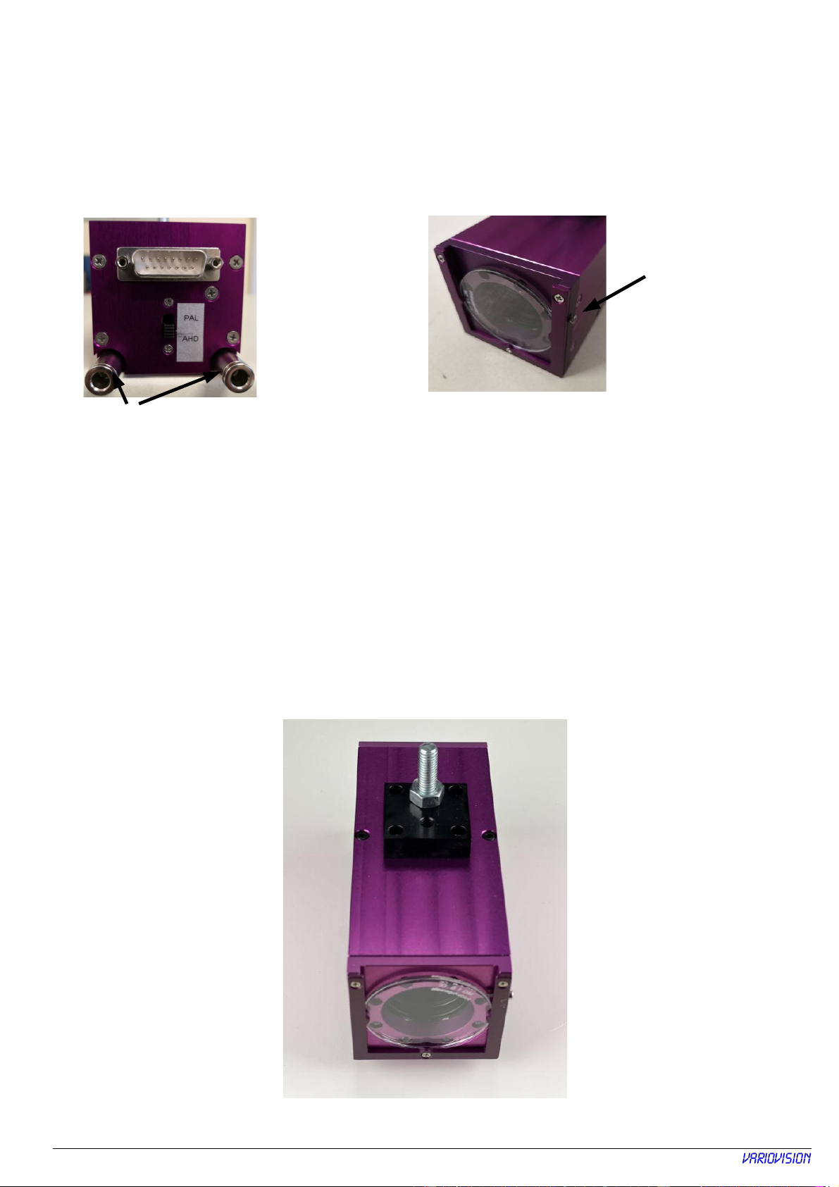
The camera is in a protective case ( 0x 0x130mm) and thereby can be inserted also in
cramped arrangements with heat and dust load. A protective glass on the front side protects
the optics of the camera and can be changed easily.
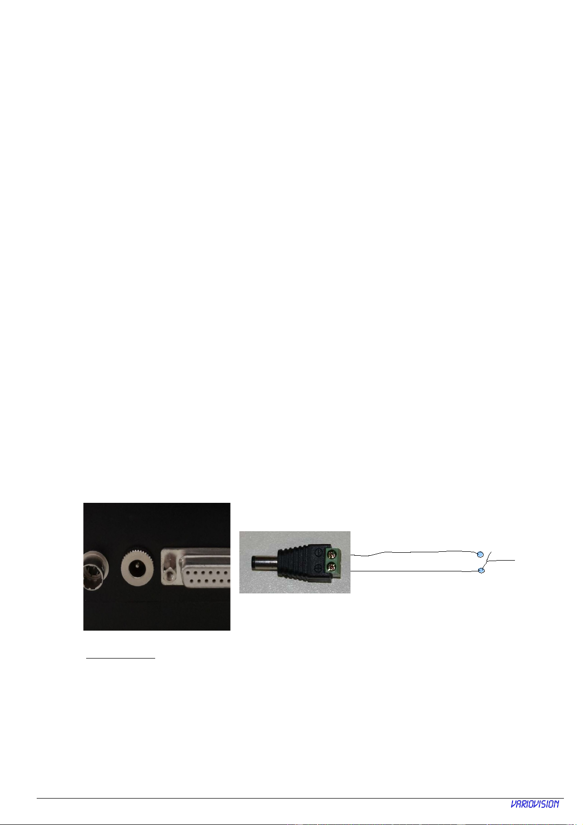
The drag chain suitable camera cable can be ordered up to 50 m length. With it, e.g., the
camera can be controlled by a remote control station or a complex cable transfer in the
machine can be carried out.
WVS-16
Version
4.1.1

Table of content
Safety instructions........................................................................................................................3
The welding vision system consists of:........................................................................................4
Connectors at front- and backside:..............................................................................................5
Operation Panel Connectors:.......................................................................................................
Rear side remote panel – Panel version:
...............................................................................................................................
7
Camera cable:
.....................................................................................
7
Dimension Panel mount version...................................................................................................8
Operation:
...................................................................................................................................
9
How to set camera parameter and brightness:
..........................................................................
9
Automatic Ext. Control:.................................................................................................................
10
Installation:
....................................................................................................................................
12
Changing of close up lenses......................................................................................................13
Specification:..............................................................................................................................14
WVS-16

Safety instructions:
Please read this manual carefully and check for the instruction before operating the WVS-
1 welding vision system.
Keep these instructions at a safe place.
Use the system only in the specified temperature and air humidity area.
Use only original power supplies for operating the system.
Do not open the case of the camera. Parts inside can be damaged or de-adjusted.
Get sure, that the power supply is disconnected, when system will be installed and cables will
be connected.
Connection cables should be moved in such a way that no one can step on it or that they can
be damaged by falling down objects.
Never pour liquids about the camera or the operating device.
Never put objects by openings of the machine. You can touch voltage-carrying shares and
receive an electric blow.
Before cleaning the system has to go is switched off and is separated from the operating
voltage. Use to the cleaning a humid cloth.
Use no sharp cleaning agents or spray cans.
With operational disturbances switch off the system and separate it from the main power. To
leave servicing works or repair work exclusively to the manufacturer.
The installation of the system may be carried out only by certified staff and must correspond to
the local regulations.
WVS-16

The welding vision system consists of:
● CCD-color video camera with zoom lens, special filters and a water-cooled case
● control panel for the camera functions
● camera cable, depending on the order, up to 50 m long
● video cable, depending on the order, up to 50 m long
● power supply
AHD to HDMI
converter
Kat.Nr.:
401 09
from Welding
machine
HDMI
cable
BNC-
cable
BNC-cable, if PAL
is used
WVS-16
When using an AHD monitor, e.g. our No. 401367, the AHD/HDMI converter and
the HDMI cable are not required

Connectors at front- and backside:
At the back of the camera is the 15 pole
Sub-D plug for the camera cable, the
BNC socket for the AHD video cable.
In the front of the camera a protective glass is
inserted which is easy to change after turn of
the small screw.
On the bottom and upper side of the camera are 4 x M3 thread for mounting an adaptor with a
M8
grub screw
and 1/4 " tripod thread. This assembly adaptor can be mounted, when
required, on lower or upper side of the camera.
ATTE TIO :
The used screws must not longer then 2 mm fit into housing.
Screw for fixing protection
glass
connector camera cable
Switch for PAL or
AHD output
Connector for cooling
Tube mm o.d.
WVS-16
When using the AHD-output, either a monitor with an AHD-input or our converter, item no. 401 09
should be used.

Operation Panel Connectors:
At the back of the operating device are the connection of the power supply, the 15 pin Sub D
socket for the connection of the camera cable, a connection for external control of the special
filter and a connector to the Monitor.
A close contact (free of potential in Ext. Control), e.g., from a welding machine, enables
automatic switching from file 1 to file 2 which saves normally camera parameters during
welding, i.e. zoom, sharpness and brightness.
Camera
Cable
Connector
Power Supply
Main Power
Switch
Ext. Control e.g.
(from welding
machine)
to
Monitor
WVS-16
To select saved adjustments of memory 1 or 2 press button to select.
After switch O the camera first uses an internal memory.
To select saved adjustments of memory 1 or 2 press button to select.

After switch O the camera first uses an internal memory.
To select saved adjustments of memory 1 or 2 press button to select.
WVS-16
Camera cable:
Rear side remote panel
–
Panel
version:
On rear side are following connectors:
4-pin connector for power supply
2-
pin connector for external control
15-pin for camera cable
BNC socket for Video (PAL or AHD)
A close contact (free of potential in Ext. Control), e.g., from a welding machine, enables
automatic switching from
memory
1 to
memory
2 which saves normally camera parameters
during welding, i.e. zoom, sharpness and brightness.
Contact is open = Memory 1 → set-up, Potentiometers without functional
Contact is closed = Memory 2 → welding, Potentiometers active
Power
supply
External
control at arc
ON
Camera
cable
Video output PAL or
AHD to Monitor

Dimension
Panel mount version:
WVS-16

Installation:
●Connection all cables before connecting the main power supply
●The assembly adaptor with a M8 grub screw and 1/4 " tripod thread is screwed on
either on upper or bottom side of the camera case. Take care that only delivered screws
are used.
●Due to high tempertures near camera please take care for proper cooling.
If needed please use the optional cooling device.
Tubes with mm of outer diameter can be mounted to the water cooling. For an
effective cooling the water flow should have a min. amount of approx. -8 l/h.
●At the assembly (mounting) of the camera is to be noted that the camera is set in
correct distance according to used close lens. This distance is to be kept - otherwise a
sharp position adjustment of the object is not guaranteed.
with close up lens distance to front of camera
+1 45...75 cm
+2 30...45 cm (Standard)
+3 22...30 cm (= combining +1 and +2)
+4 1 ...22 cm
●The camera cable is drag chain suitable. The length may be to maximum 50 m. The
15pin Sub D socket is camera-sided, while on operating panel side is a 15pin Sub D
plug. The pinning is one to one. The copper-shield is connected with the sockets and
plug case. The system can therefore from the camera up to the operating panel connect
to ground/earthing by the yellow/green earthing connection..
WVS-16
Automatic Ext. Control
Please note:
DIM-Function is only active if the contact on ext. control is closed
From Welding machine

Operation:
The desk-shaped operating device is easy to use by the arrangement of the functional keys
and the dimmer. The dirty-insensible foil keyboard can be easily cleaned with a humid cloth.
Drawing: 2 zone filter
The button SET
activates the camera
memory, by holding of
SET button and a
memory key, e.g., 2 the
instantaneous camera
setting is written in the
memory 2 and is there
as long as retrievable to
this memory 2 is new
headlined.
BRIGHT opens the
aperture and makes a
brighter picture
DARK closes the
aperture and makes
with a darker picture
NEAR shortens the
sharpness level forwards FAR extends the
sharpness level to the
back
TELE causes zoom in,
the object appears
bigger
The buttons 1 and 2 are memory buttons,
2 different camera settings can be stored
and recalled.
LED power indicator
WIDE causes a wide
corner view, i.e. the
object becomes smaller
The potentiometer DIM
has 2 controls to adjust
the 2 grey filters so that
the light amount to the
camera is adjustable any
time. The lower control
steers the light amount
of the whole picture, the
top control steers only
the upper half of the
picture (see drawing 2
zone filter)
WVS-16
Function button 3 see
Table "Function of buttons"
only at WVS-16
with 2 filter system
included

Function of buttons
Wide Increase field of view
Tele Decrease field of view
ear Set focus more near
Far Set focus more far
Bright Open Iris
Dark Close Iris
1Recall parameter (e.g. set-up of welding)
2Recall parameter (e.g. during welding)
3Image left/right reverse
Set + 1 Set current parameter
Set + 2 Set current parameter
Set + 3 turn Image by 180°
Set + Wide Switch to manual White Balance
Set + Tele Switch to automatic White Balance
Set + ear Increase Red part of Image (only at manual Whitebalance)
Set + Far Decrease Red part of Image (only at manual Whitebalance)
Set + Bright Increase Blue part of Image (only at manual Whitebalance)
Set + Dark Decrease Blue part of Image (only at manual Whitebalance)
A is displayed on Monitor when automatic White Balance is active
M is displayed on Monitor when manual White Balance is active
R and B show values for each ( 0….20)
WVS-16

How to set camera parameter and brightness:
Switch the welding vision system on. After the self test a video picture should appear on the
videomonitor.
Set your field of view with TELE and WIDE. Adjust focus with NEAR and FAR. Set brightness
by pressing DARK and BRIGHT
Save this information by pressing SET and 1 simultaneous.
Now press DARK until picture is much darker
Repeat saving by pressing SET and 2.
After starting the welding process, the close contact from the welding machine switches
internal from file 1 to file 2 and parameters from file 2 are used. The fine regulation for the
brightness can now done with the DIM potentiometer.
If picture is still to bright press DARK again until brightness is acceptable.
Repeat saving by pressing SET and 2.
After finishing the welding (i.e. If the contact on ext. Control is open) an automatic change
back to file 1 happens. Potentiometer DIM is now without function.
Please note:
DIM-Function is only active if the contact on ext. control is closed
WVS-16

Changing of close up lenses:
Building up the camera please note, that the camera is mounted in the right distance to the
work peace according various close up lens. The distance has to be kept; otherwise it could be
that the object cannot be focused correctly.
Distance close up lens to front-side of the camera
+145...75 cm
+230...45 cm
+322...30 cm (= +1 and +2 together)
+41 ...22 cm
To change the close up lenses please follow the following instructions
Open the camera, according the following pictures
Remove this screws, also on opposite side
Remove the front plate with the LED ring light
For reassembling please check the polarity of the connector
Now you can adjust the distance by using the various close up lenses.
Please chose the close up lenses according the table above
The reassembly occurs in reverse order.
WVS-16

Specification:
Sensor: 1/3“ CMOS, 2,12 MPixel, 700 TV Lines,
752 x 582 Pixel
Lens : 10-fold optical zoom,
f= 5,1mm, 54°, Wide
f= 52mm, 4,9°, Tele
Shutter: fixed at 1/50 sec.
Aperture: F=1,8 to F=20
Video output: FBAS, 1 V p_p (Sync. Negativ) on remote panel
Automatic white balance ATW
Manuell focus for optimal adjustment
2 memory spaces for user parameter
Camera cable up to 50m
Power: 12 VDC, 250 mA
Operating temperature: 0...50 ° C
Size: Camera 0 x 0 x 140 mm,
Panel 135 x 190 x 55 mm (W x D x H)
Weight: Camera only appr. 50 g
WVS-16
Variovision Thomas Stelzl
Pöttinger Straße 23
DE-82041 Oberhaching
Tel. +49 89 23967195
Fax +49 89 23967196
www.variovision.tv
www.weldingcamera.com
Spare parts
Description: Art.-No.
Protective Glas 402461
Power Supply
402501
100 – 240 VAC to 12VDC
Table of contents