VASTEX DB-30 User manual

DB-30 & DB-II-30
Conveyor Drying System
Assembly & Operating Manual
Introduction / Safety 2
Assembly 3-4
Component Identification 5-6
Operation 7
Maintenance 8
Troubleshooting 9
Dryer & Exhaust Hood Ducting 10
Installation: Conveyor Belt Covers 11
Warranty / Terms & Conditions 12
Serial Number:
(Please log your machine's serial number and date of purchase for future reference.)
Date:____/____/______
Electrical Drawing #: Rev:______
Pg #
Doc # 01-01-013C
VTX
Vastex
International, Inc.
1032 N. Irving St.
Allentown, Pa. 18109 USA
Phone# 610 434-6004 Fax# 610 434-6607
Web Site www.vastex.com
Authorized Representative in Europe:
Certification Experts BV
Nieuwstad 100 1381 CE Weesp,
The Netherlands
Tel : + 31 (0) 294 – 48 33 55
Vastex E-mail assistance
Purchasing & Product Info:
Electrical Support:
stech@vastex.com
Tech Support, Mechanical Setup, and Operation:
techsupport@vastex.com
Screen Printing Issues & Support:
Original Instructions
Year of Manufacture: 20____
DB-30 Shown as table top
model, optional legs availa-
ble.
DB-II-30 is floor model only.

The Instruction Manual and Safety Instructions must be read and understood by anyone
operating the Vastex Conveyor Drying System.
The operator should read and understand the instruction manual before operating this equipment.
Store instruction manual and safety instructions near equipment for easy access to operators.
VASTEX Conveyor Drying System is intended for the curing of non-flammable inks on screen printed
materials. Do not use for any other purpose unless authorized by Vastex International, Inc. Use of this
equipment for any other purpose can be dangerous and may cause damage to this equipment, voiding
the warranty.
It is recommended that the area around this equipment be designated as a work area and only author-
ized employees be allowed in the area.
Children and pets must be kept clear of the work area.
Do not place any objects on top of the drying chamber. Surfaces are hot!
Never leave equipment unattended.
Do not operate conveyor or dryer with any cover or guard removed.
Operator must be familiar with controls of the dryer and conveyor.
Never put excessive load on the conveyor belt.
Before starting production, the operator must check that all covers and guards are in place, no material
has been left on the conveyor, and the work area is clear of obstructions.
Switch on and verify conveyor belt is moving before turning on the heat.
Allow dryer to cool to 300°F (149°C) before switching off conveyor.
Always turn off power at the main disconnect at the end of production.
In case an abnormal symptom occurs, for example excessive vibration, noise, and strong smell or
smoke development, turn off the VASTEX Conveyor Drying System and contact a qualified technician.
Immediately turn off the VASTEX Conveyor Drying System if products become jammed in the drying
chamber or conveyor belt.
Do not remove any cover or guard until power at the main disconnect is switched off and locked out.
No unauthorized persons are to be allowed inside the control boxes.
Turn off and lock out power at the main disconnect before any cleaning or maintenance.
Only qualified technicians should be allowed to make repairs on the VASTEX Conveyor Drying System.
Noise and vibration: This equipment does not produce noise in excess of 70 dB(A) at workstations.
Stability during use, transportation, assembly, dismantling when out of service, testing, and fore-
seeable breakdowns: This equipment is designed and expected to be stable during all foreseeable con-
ditions, so long as the procedures and instructions given in this manual are followed. When dryers are as-
sembled onto legs, it is recommended that two or more people stand the unit upright after bolting legs on.
Safe handling, transport, and storage: Before storing the unit, follow the shutdown procedure on P. 8 to
allow the heater assembly to cool properly. No special handling considerations are necessary, except to
be aware of the weight of the equipment and take standard precautions for moving such weights:
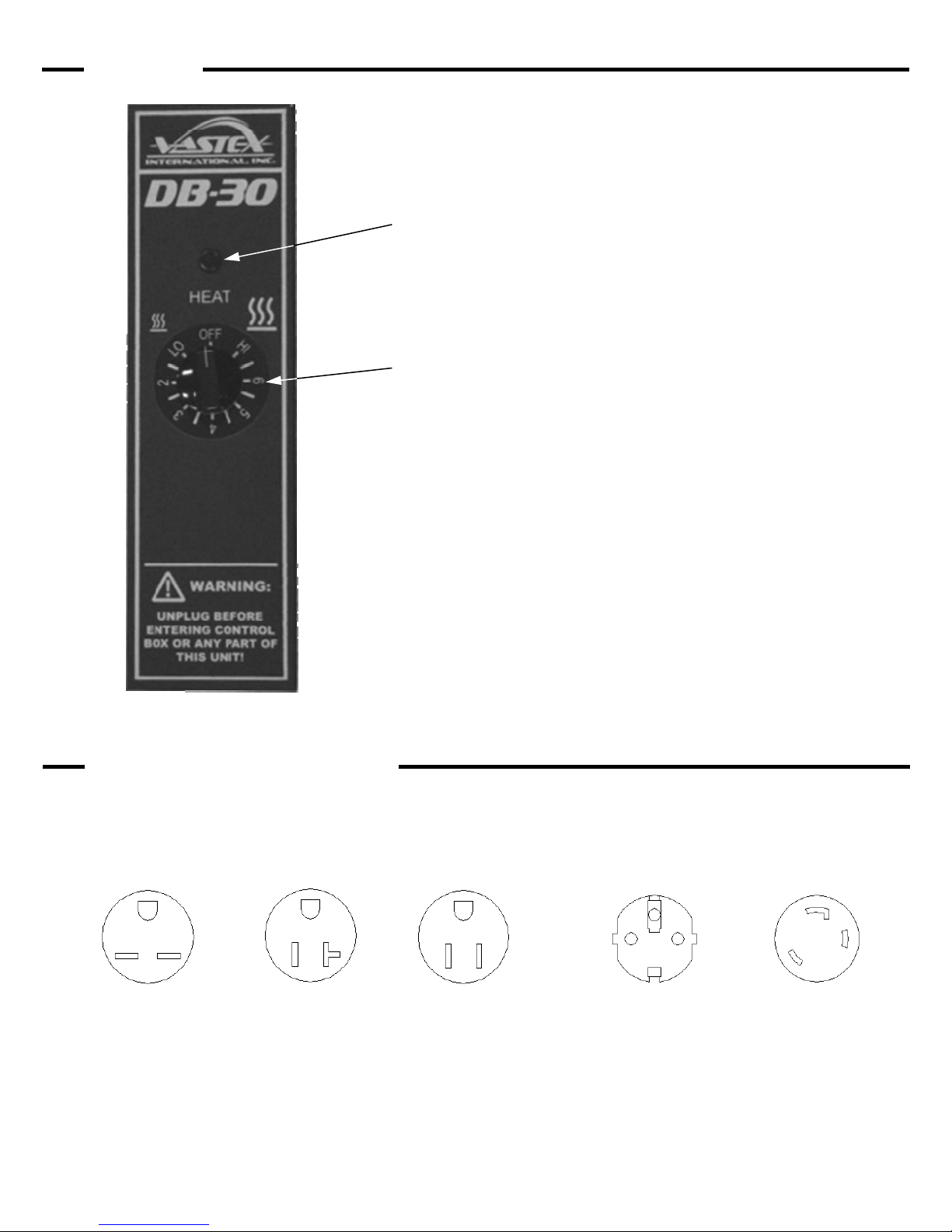
DB-30:
Main Unit: 265 lbs (120.2 kg)
Optional Legs: 30 lbs (13.6 kg)
Optional locking casters are available for all DB-series dryers equipped with legs. When equipment is
to be moved frequently, it is recommended that these be installed.
Introduction
Congratulations, you have chosen a VASTEX conveyor curing system. VASTEX has been designing and
building dryers since 1960 and has the knowledge and expertise to supply a quality dryer and help you keep it running
for years to come. VASTEX has innovated many of the features found in conveyor ovens today from control methods,
modular features, air movements and belt tracking.
Your Vastex Infrared Dryer has been Factory tested and burned in for a period of 2-8 hours. All components
Safety
DB-II-30:
Main Unit: 465 lbs (210.9 kg)
Included Legs: 30 lbs (13.6 kg)
2

Assembly
Front
Section
Drive
Section
4) Turn the conveyor right side up. Install the chain guard with the
(2) black #8 machine screws. See Maintenance section for chain
adjustment
Belt
1) The conveyors are assembled in the same way for all DB-Series dryers. The DB-30 is being used for
the pictures. Remove the conveyor parts from skid and lay out on a large table or the floor as shown.
2) Bolt together all sections of the conveyor. Each section is bolted to the
next using (2) 3/8”x 3/4” bolts, serrated locknuts. Photo on right.
1
3) Install the (Optional) leg assemblies using
(2) 3/8” x 3/4” bolts and serrated locknuts
on each leg assembly.
Leg Assembly
(optional)
2
3
4
Tools Needed: (2) 9/16” open end wrenches, (1) 7/16” open end wrench or socket, (1) 1/4” nut driver OR flat blade screw driver
3/8” x 3/4” bolt
3/8” Serrated Locknut
Chain Guard
Do not operate with Chain Guard
removed. Serious Injury may result!
3/8” x 3/4” bolt
3/8” Serrated Locknut
3

5) The belt needs to be installed as shown in the diagram below. Be sure the belt is routed under the brace found near
the gear motor. To connect your belt, align the Alligator Lace and install the pin. Some belts will have a plastic flap
over the Alligator Lace. Position it as shown in the diagram.
Alligator lace
Aligner Brace
6) The belt needs to be tightened and adjusted. To tighten and
adjust the belt, use the Aligner Bolts. To raise the Aligner, turn
the Aligner Bolt clockwise with a 7/16” wrench. To lower it, turn it
counter clockwise. Raise the Aligner until you have about 2”-2½”
of slack as shown on right.
5
5
6
Aligner Bolt
8) Place the Heat Chamber on the conveyor, centered between the belt’s rollers, with the Control Panel on the right side.
10) Tracking the belt is the final step in setting up your Dryer. The belt speed should be turned up during belt tracking.
The model below shows how to track the belt. Be sure to adjust the Aligner bolts at 1/4 turn at a time. The dryer
should be on a flat surface for proper belt tracking.
Assembly (cont’d)
Belt moving to the right
Belt moving to the left
CW
CW
CCW
CCW
Raise this side
Raise this side Lower this side
Lower this side
01-16-005A Belt Tracking
Belt Travel
9) Electrical Connections
Chamber: Refer to the wiring diagrams included with your dryer. Several combinations available.
Conveyor: Refer to plug diagrams on the Control page. Conveyors are available in either 120V or 240V
120V, 1 Amp, 50/60Hz 240V, .5 Amp, 50/60Hz
Belt
Alligator Lace
Plastic Flap
Aligner Rail
Front Pulley
Rear Pulley
7) Install the three conveyor belt covers. See supplied document
01-01-014 for installation.
4

Conveyor Components
IR Heater
Gear Motor
Belt
Aligner
Front Pulley
Belt The conveyor belt is made of Teflon coated fiberglass. It is joined together with an alligator lace using a
steel pin to connect each side. The belt will not burn under normal conditions but the dryer should always
have the belt moving while the heaters are above 300 degrees (149 deg. C). The belt should remain
tracked in the center of each pulley. (See “Belt Installation and Tracking” for adjustment instructions.)
Aligner The aligner is a device for tracking the belt and keeping it on the pulley. As the belt moves from side to
side the aligner is used for adjustments to keep it centered. The belt does not have to be perfectly cen-
tered on the pulley but should not be hanging over either edge.
Pulley The pulleys at either end of the conveyor are made by VASTEX of 4 ½ inch tubing with ¾ inch center
shaft. They are mounted on self aligning flange bearing blocks for precision rolling.
Gear Motor A 90 Volt DC gear motor is located to the rear of the conveyor. It drives the rear pulley and belt with a
roller and a #25 chain.
IR Heater The infrared heaters in VASTEX dryers emit medium wave infrared heat, perfect for curing plastisol inks.
The heater connections are located in the trough on the right side of the heater, connected with high tem-
perature terminals and stainless steel socket head cap screws.
Control Box The Control Box houses the Variable Heat Control and a Heat Light.
Exhaust Stack 4” unpowered exhaust stack. (Optional) Exhaust booster can be added here to pull fumes out of the
chamber and exhaust outside.
Chamber Components
Component Identification
Control Box
Exhaust Stack
Rear Pulley
(DB-30 Shown)
5

Controls
240 Volt 15 Amps
Nema 6-15R
DB-240, DB-30, DB-18-240
240 Volt “X”Series Conv.
120 Volt 20 Amps
Nema 5-20R
DB-120, DB-18 &
DB-30-120
120 Volt 15 Amps
Nema 5-15R
120 Volt “X”Series Conv.
120 Volt Exhaust options
120 Volt Scrub Air
240 Volt 2.5 to 15 Amps
CEE 7/7
All Continental Europe
Machines under 16 amps
240 Volt 22 Amps
L6-30R
DB-II-18 & DB-II-30
Receptacle Configuration
The Diagrams below show the possible Receptacles needed for the conveyor and chamber of your DB-Series
Dryer.
Heat on Light
This RED light is wired to the controller. It will
illuminate when the control is turned on, even
if the controller has failed.
Variable Heat Control
The control has positions LO-2-3-4-5-6 and HI. The controller
turns the power to the heater on and off to vary the tempera-
ture. The higher the number on the controller the longer the on
cycle and shorter the off cycle is. The HI position keeps the
power on constantly.
6

Dryer Operation
Set the Belt Speed: Rotate the Belt Speed Control Knob clockwise to increase speed and counter-clockwise to
decrease it. For Plastisol inks, a good starting point is 20-25 seconds in the chamber. The
dial numbers are for reference only. They do not represent seconds in the chamber.
Set the Heat: With the dryer plugged in, rotate the Variable Control Timer to the desired setting. Often times, it is
best to run the dryer on HI and adjust your belt speed and heater height to achieve a proper cure.
Curing Plastisol with infrared:
Plastisol ink can fully cure in approximately 20-30* seconds. The ink must achieve 310°-320° F (154°-160°C) to cure and fuse to
the garment.
Discharge or water based: (A powered exhaust is recommended)
Water based products require more time than plastisol to cure due to the fact that the water/moisture must be evaporated before
the ink can cure. We have seen cure times from 50 to 90* seconds to achieve a full cure or discharge and not damage the gar-
ment. Please note as the time is increased the temperature must be decreased to protect the garment from scorching.
*Actual cure times can vary depending on conditions such as garment moisture and color, ink color, ink thickness, and
environmental conditions. All three variables should be used to maximize production while insuring a proper cure.
Turn on the Heat: Turn the Variable Heat Control dial on HI for 10-15 minutes to allow the dryer to warm up.
Set the Heater Height: Set the desired heater height for your job. On each side of the heating chamber, there is a knob to
raise and lower the heater. On DB-II models, there are (2) knobs on each side. It is recommended
to run the heater height at about 2” - 3” above the garment. The heater can be run at an angle for
curing non-flat substrates such as hats.
Turn on Conveyor: Set belt speed with the Belt Speed Control on the conveyor, near the motor.
Check belt path: Remove any objects from the conveyor and belt.
Turn on Power Be sure your breaker is in the off position and the dryer’s dial controls are off. Plug the
Conveyor and Chamber into their properly rated outlets and turn the breaker on.
Startup Procedure
Operation Tips
While machine is in operation, it is necessary to have the belt moving while the heater is above 300°F (149°C).
Allow approximately 15 minutes for dryer to reach Full temperature.
If no garments are being run through the dryer for more than 10 minutes, it is recommended to lower the dryer to
“4” or lower. It will take approximately 10 minutes to return to operating temperature.
Periodically check ink temperature at the exit of the dryer. It is recommended that you check the temperature of
the ink towards the outside of the printed image.
When checking temperature with a laser gun, shoot the ink while it is still under the heating elements.
Turn off Breaker: Turn off the breakers controlling your DB-series dryers at the end of each shift and unplug
them from their outlets.
Turn off Conveyor: Once the dryer cools down to 300°F (149°C) or lower, turn the Belt Speed down to the off
position. Skip this step if leaving the conveyor belt speed set for the following shift.
Turn off Heat: Turn the Variable Control Timer off. Allow the heaters to cool for 10-15 minutes before shut-
ting the conveyor off. Belt damage may result from stopping the conveyor with hot elements.
Shut Down Procedure
7

Motor sprocket
Belt speed control knob
Fuse holder Power cord
Belt speed control
Gear Motor
X-Series conveyor control assembly.
Model# XCB-DB-XXX
(XXX = 120 or 240 volt)
Caution:
With the control assembly removed there are
open wires and electrical connections.
Severe shock can occur if caution is not taken.
Chain Guard
To remove the chain guard:
Unfasten the two black sheet metal
screws at the top. Be sure to replace
the guard after adjustment is made.
In order to adjust the chain tension or remove the control assembly, the chain guard must first be removed.
Control assembly
mounting screws.
Control assembly
mounting screw
Drive Chain Adjustment
To adjust the drive chain, loosen the (3) control assembly mounting screws. Adjust any slack out of
conveyor chain and retighten screws.
Caution! Do not over tighten chain, damage to bearings may occur.
Maintenance
Electrical Electrical connections will loosen in time from heating and cooling. Every three (3) months the power should be turned
off at the external disconnect, or unplugged, and all the points of connection should be inspected and tightened.
Lint Buildup As with your clothes dryer at home lint will build up where ever air is flowing over garments.
Every six months
-The top cover should be removed to clean around the heater and any other visible debris buildup.
Every 2-3 months
-The optional exhaust blower, located on the rear of the machine, should be cleaned. To open the back panel
of the exhaust blower, remove the (14) black #8 machine screws for access to the blower.
Motor Chain Chains can loosen in time and should be inspected, adjusted, and lubricated when necessary. The motor chain is locat-
ed in the rear of the conveyor behind the Chain Guard.
Connections
Caution! Power must be turned off at the external disconnect, or the machine unplugged,
before entering any part of this machine. A qualified electrician should perform any internal
testing requiring power on!
DO NOT RUN YOUR CONVEYOR
WITHOUT THE CHAIN GUARD IN
PLACE.
8

Red Pilot Light out
Loose connections
Customer power failed or outlet failed
Controller bad
Check connections
Check power at main disconnect
Replacement controller
Red Light on
Loose connections
Bad controller
Bad Heater
Check connections
Replace controller
Replace Heater
Heat not cycling on
and off Bad controller Replace controller
Possible Cause
Solution
IMPORTANT Turn off and lock out power at the main disconnect before entering
any part this equipment . Do Not operate with any covers or guards removed.
Troubleshooting
Please set controller to at least “5” for diagnostics.
This view of the control
assembly “upside down” is
to show you the speed pot
adjustments on the bottom
side of the controller.
Pot near the white wires LOW SPEED. Pot near the blue wires HIGH SPEED.
Setting the low speed pot adjustment: (small screw driver with plastic handle is needed)
Turn the speed pots clockwise to increase the speed and counterclockwise to decrease. The low speed pot should be set so
the belt (or sprocket) moves very slow at the lowest setting on the controller, just before the controller is clicked in the off
position. The high setting is set so 90 VDC is the maximum voltage to the motor, a volt meter is needed for the high speed
adjustment. The control assembly should be placed on a bench so the speed pots are up and accessible.
Caution: Do not to touch the open wires around the controller and the fuse holder.
Belt Speed Controller adjustment
Motor still turning Broken chain drive
Loose sprocket set screws
Replace chain & worn sprockets
Tighten sprocket set screws
Motor & drive pulley are turning Obstruction in belt path
Belt loose
Clear jam
Tighten belt
Possible Cause
Solution
Belt Stopped
No Heat
9

10

Vastex International, Inc.
1032 N. Irving St.
Allentown, Pa. 18109 USA
Phone# 610 434-6004
Fax# 610 434-6607
Web Site www.vastex.com
E-Mail info@vastex.com
Installation: Conveyor Belt Covers
DB Series and EC-I Series Dryers
Doc. # 01-01-014
Tools Required: 1/4” Nut Driver, or 1/4” socket and ratchet
Package Contents:
(3) Belt Covers (actual covers may differ from pictures)
(1) Chain Guard
(8) Sheet Metal Screws
Conveyor Front
Belt Cover
(2) Screws
Belt Cover
Conveyor Rear
(2) Screws
Chain Guard
11

Vastex Warranty
Doc#01-00-005B Revised 04/10/12
(1.) Vastex, hereinafter referred to as “seller” warrants only to its original “purchaser”, who holds a copy of the original invoice and is the original end user of the equipment in question,
its new equipment against defects in materials or workmanship on a pro-rated basis. Warranty period begins from date of shipment to the buyer and will only apply to customers paid in
full. Warranty periods are as follows: one (1) year for E-1000, three (3) years for all other complete machines (including F-Flash), fifteen (15) years for infrared heaters (excluding F-
Flash) installed by Vastex in a new dryer, three (3) years for replacement infrared heaters, and one (1) year for replacement parts. Rubber blankets, light bulbs and glass on exposure units
are particularly subject to wear while in use. Wear is not covered by this warranty but as stated above only manufacturers defects are covered. All sales made through Vastex dealers must
be certified by that dealer before a warranty replacement is issued.
(2.) This warranty is expressly contingent upon the buyer delivering to seller, at the address below, with all transportation charges prepaid, the part or parts claimed to be
defective within the above mentioned warranty periods stated in paragraph one. The defective part or parts will be repaired or replaced at the discretion of Vastex Internation-
al, Inc. If the equipment in question is less than one (1) year old, it will be shipped to the customer at no charge, with an RGA issued by Vastex for the defective part. The defec-
tive part must be shipped back to Vastex freight prepaid within 30 days or the account will be billed. If the equipment is more than a year old, the part will be shipped after we
receive the defective part. If it’s necessary to expedite the movement of parts and to minimize down time to the buyer, the replacement part shall be supplied on a C.O.D. basis.
If testing and analysis of said part by the seller or its supplier discloses that said part is defective, the cost of said part will be refunded to the buyer on a prorated basis.
(3.) Except as otherwise provided herein, the equipment is being sold “as-is”. Final determination of the suitability of the equipment for the use contemplated by the buyer, is the sole
responsibility of buyer, and seller shall have no responsibility in connection with the suitability.
(4.) All warranties implied by law, including the implied warranties of merchantability and fitness are hereby limited to workmanship and defective parts to a warranty period stated in
paragraph one. The express warranty and remedies contained herein and such implied limited warranties are made solely to the sole warranties and remedies and are in lieu of all other
warranties, guarantees, agreements, and other liabilities, whether express or implied, and all other remedies for breach of warranty or any other liability of seller, in no event shall seller be
liable for consequential damages.
No person, agent, distributor, or service representative is authorized to change, modify or extend the terms hereof in any manner whatsoever.
These terms and conditions are an essential part of the transaction between the parties and constitute the entire agreement between them with respect to the same.
Some states do not allow limitation on how long an implied warranty lasts of the exclusion or limitation of incidental, or consequential damages, so the above limitation may
not apply to you.
This warranty gives you specific legal rights, and you may also have other rights which vary from state to state.
Infrared heaters are the only replacement parts covered for a period of (3) years from date of shipment and contingent to receipt of payment in full.
Electrical components cannot be returned once installed unless proven defective.
Please refer to doc. 01-00-015 for specific terms and conditions of sale and the limited warranty.
Please refer to doc. 01-00-017 for V-2000HD printer warranty.
Updates: V1000 to 3 year warranty 01/09/12, Heater warranty to 15 years 01/02/2012.
---------------------------------------------------------------------------------------------------------------------------------------------------------------------------------------------------------------------
TERMS AND CONDITIONS OF SALE AND LIMITED WARRANTY Doc.#01-00-015
1. Buyer’s order will constitute an offer in accordance with the terms hereof and such offer, upon acknowledgment of Seller, will constitute the agreement between Buyer and Seller.
Buyer’s order after such acknowledgment by Seller will not be subject to cancellation, change or reduction in amount, or suspension by Buyer of deliveries, unless prior to such
action Buyer has obtained Seller’s written consent. Notwithstanding anything to the contrary in Buyer’s Purchase Order or other communications, the parties agree to be bound by
these Terms and Conditions. Acceptance of the product by the Buyer shall be deemed to constitute unconditional acceptance of these Terms and Conditions.
2. Any of these terms, conditions and provisions of Buyer’s order which are inconsistent with Seller’s acknowledgment and these Terms and Conditions of Sale shall not be binding
on the Seller and shall be considered not applicable to any sale so made. No waiver, alteration or modification of any of the provisions on either side of the document shall be
binding upon Seller unless agreed to in writing by Seller.
3. (a) All prices are F.O.B. Seller’s Plant and method of delivery and routing shall be at Seller’s discretion, unless specifically otherwise stated herein. Notwithstanding any agreement
to pay freight, delivery of products purchased hereunder to a common carrier or licensed trucker shall constitute delivery to Buyer and be determinative of the date and time of
shipment and all risk of loss or damage in transit shall be borne by Buyer. If the Buyer fails to accept the goods from the common carrier or licensed trucker, the Seller shall be
entitled to claim payment from the Buyer. Seller shall arrange for storage, the risk and the cost, including insurance costs, to be borne by the Buyer (and Buyer agrees to pay
such amounts upon demand) except if the failure to accept delivery is due to any of the exceptions noted in Paragraph 4.
(b) Terms of payment shall be as stated on invoice.
4. It is understood that deliveries will be made in accordance with Seller’s regular production schedule. Every reasonable effort will be made to meet the Buyer’s required delivery
dates but Seller will not be liable for damages or be deemed to be in default by reason of any failure to deliver or delay in delivery due to any preference, priority, allocation or
allotment order issued by the Government, whether Federal, State or local, or causes beyond its control including but not limited to, Acts of God or a public enemy, acts of Govern-
ment, fires, floods, epidemics, quarantine restrictions, strikes, lockouts, freight embargoes, severe weather, unavailability of materials or shipping space, delays of carriers or sup-
pliers or delays of any subcontractors. Should delay in delivery be caused by any of the circumstances mentioned in this paragraph, such extension of the delivery period shall be
granted as is reasonable under the circumstanced of the case. Should delay be caused by an event not specifically mentioned in this paragraph, damages will be limited to cancella-
tion of the purchase order without penalty, and refund of any monies deposited or prepaid on the purchase order with no liability for any consequential or incidental damages.
5. Seller reserves the right to increase the prices prior to Seller’s acceptance of order and/or after expiration of any price quoted by Seller.
6. Unless otherwise stated in writing, Seller’s prices do not include sales, excise, value-added or other taxes. Consequently, in addition to the price specified herein, the amount of any
present or future sales, use, excise, value-added or other tax applicable to the manufacture, sale, purchase or use of the products hereunder shall be paid by Buyer, or in lieu thereof,
Buyer shall provide Seller with a valid tax exemption certificate acceptable to the taxing authorities.
7. Seller reserves the right, at any time, to revoke any credit extended to Buyer because of Buyer’s failure to pay for any products when due or for any other reason deemed good and
sufficient by Seller and in such event, all subsequent shipments shall be paid for prior to at delivery at Seller’s option.
8. (a) SELLER’S LIABILITY SHALL BE LIMITED TO SELLER’S STATED SELLING PRICE PER UNIT OF ANY DEFECTIVE GOODS AND SHALL IN NO EVENT IN-
CLUDE BUYER’S MANUFACTURING COSTS, LOST PROFITS, GOODWILL, OR ANY OTHER SPECIAL, INDIRECT, INCIDENTAL OR CONSEQUENTIAL
DAMAGES, ARISING OUT OF THE AGREEMENT, THIS CONTRACT, THE SALE OF THE PRODUCTS TO THE BUYER OR THE USE OR THE PERFORMANCE
OF THE PRODUCTS. Seller may at its discretion repair, replace or give the Buyer credit (pro-rated) for such defective products.
(b) Notwithstanding anything herein to the contrary, Seller shall have no liability for alleged defects with the products which are not specified in written notice from the Buyer to
the Seller within thirty-six (36) months from the date of shipment of machines. Seller shall pass to Buyer any warranty received by Seller from the manufacturer of Limited
Life Components, which in most cases is 12 to 18 months.
(c) Seller shall have no liability under this Limited Warranty unless Buyer has paid in full for the products. Further, this Limited Warranty is expressly contingent on Buyer’s deliv-
ery to Seller, all costs prepaid, the defective part(s) within thirty-six (36) months of shipment to Buyer, together with a written statement specifying the alleged defect(s). Any
replacement part(s) shall be shipped to Buyer on a C.O.D. basis.
(d) SELLER SPECIFICALLY EXCLUDES ALL WARRANTIES, EXPRESSED, IMPLIED OR OTHERWISE, EXCEPT AS STATED EXPLICITLY IN THESE TERMS AND
CONDITIONS OF SALE. SELLER DISCLAIMS THE WARRANTY OF MERCHANTABILITY AND FITNESS FOR A PARTICULAR PURPOSE.
9. The remedies herein reserved by Seller shall be cumulative and in addition to any other legal remedies. No waiver of a breach of any portion of this contract shall constitute a
waiver of continuing or future breach of such provision or of any other provisions hereof.
10. These Terms and Conditions constitute the entire agreement of the parties. No amendments, changes, revisions or discharges hereof in whole or in part shall have any force or
effect unless set forth in writing and signed by the parties hereto. This contract shall not be assignable by Buyer voluntarily by operation of law or otherwise without Seller’s writ-
ten consent.
11. This contract shall be governed and shall be construed according to the domestic laws of the Commonwealth of Pennsylvania.
12. Anything herein to the contrary notwithstanding, any action for alleged breach by Seller of the contract between the parties, including but not limited to any action for breach of the
warranties herein set forth, shall be barred unless commenced by Buyer within one (1) year from the date such cause of action accrued.
13. This agreement shall inure to the benefit of and be binding upon the parties hereto, their respective successors and permitted assigns.
14. All notices required by this contract to be given by either party shall be sent in writing or by facsimile and shall be addressed to the last known address of such other
party. Notices shall be deemed to have been received on the fifth business day following deposit in the mail.
12
This manual suits for next models
1
Table of contents