Vayyar V60G-HOME-I User manual

V60G-HOME-I Module
User Manual
Revision 1.0.5

V60G-HOME-I User Guide
Vayyar Confidential
Page 2 of 19
Vayyar Imaging Ltd.
Web: https://vayyar.com
Notice
Copyright 2020 Vayyar Imaging Ltd. All rights reserved.
This document is the property of Vayyar and all materials and information contained herein are the confidential and proprietary
information of Vayyar and are protected by international copyright laws. The copyrights are owned by Vayyar or the original creator of the
material. The materials and information contained herein are provided to you for internal information purposes only, and no portion of
the materials and information herein may be copied, reproduced, distributed, transmitted, displayed, published, broadcasted or used in
any way whatsoever directly or indirectly without the prior written consent of Vayyar or in any case of third party materials, without that
third party's consent. This document shall be returned to Vayyar promptly upon request.
The materials and information contained herein are provided "AS IS" and Vayyar does not provide any warranties of any kind, whether
express or implied, including but not limited to implied warranties of merchantability, fitness for a particular purpose, and non-
infringement
Revision History
Revision
Date
Author
Description
1.0.1
February 2020
1.0.2
March 2020
1.0.3
August 2020
Canada
1.0.4
September 2020
Canada
1.0.5
October 2020

V60G-HOME-I User Guide
Vayyar Confidential
Page 3 of 19
Table of Contents
CHAPTER 1 INTRODUCTION .....................................................................................................6
1.1 Release Information Note.......................................................................................................6
1.2 Glossary...................................................................................................................................7
CHAPTER 2 SYSTEM OVERVIEW................................................................................................8
2.1 System Architecture................................................................................................................8
2.2 Hardware ..............................................................................................................................10
2.2.1 Sensor Unit Specification ..............................................................................................11
2.2.2 Digital Interface.............................................................................................................12
2.2.3 RF Interface - Antennas.................................................................................................13
2.2.4 Electrical Specifications.................................................................................................13
2.2.5 Antenna and RF Characteristics....................................................................................14
2.3 Software................................................................................................................................15
CHAPTER 3 REGULATORY SECTION......................................................................................... 16
3.1 Compliance ...........................................................................................................................16
3.1.1 FCC ................................................................................................................................16
3.1.2 IC ...................................................................................................................................17
3.2 Instructions for the Integrator..............................................................................................18
3.2.1 OEM Integrators Notices...............................................................................................18
3.2.2 End Product Labeling ....................................................................................................18
3.2.3 OEM Manual Information that Must be Included ........................................................18
3.2.4 RF Exposure Guidance...................................................................................................19

V60G-HOME-I User Guide
Vayyar Confidential
Page 4 of 19
List of Figures
Figure 1: V60G-HOME-I “EVK” System Architecture...............................................................................8
Figure 2: V60G-HOME-I “Embedded” System Architecture ...................................................................9
Figure 3: High-Level Block Diagram –USB-based system.....................................................................10
Figure 4: vStraw_CTPB4 Connectivity...................................................................................................12
Figure 5: vBLU_OK _CTPB4 connector..................................................................................................13
Figure 6: Antenna Positions and Numbering........................................................................................13
Figure 7: V60G-HOME-I Antenna Pattern.............................................................................................14
Figure 8: Processing Flow......................................................................................................................15

V60G-HOME-I User Guide
Vayyar Confidential
Page 5 of 19
List of Tables
Table 1: Glossary.....................................................................................................................................7
Table 2: Sensor Unit Specification ........................................................................................................11
Table 3: Sensor Unit Electrical Specification.........................................................................................14
Table 4: Antenna and RF Characteristics ..............................................................................................14

V60G-HOME-I User Guide
Vayyar Confidential
Page 6 of 19
Chapter 1
Introduction
This guide provides information on the installation and operation of the Vayyar V60G-HOME-I
modules.
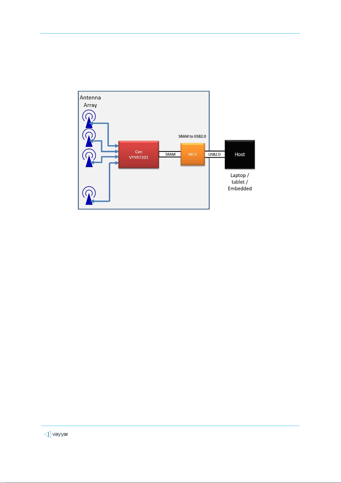
V60G-HOME-I is a family of multi-antenna millimeter-wave modules operating at 60GHz bands, based
on the company’s VYYR7201 RF SoC, generating a 3D image of the sensor’s vicinity by transmitting and
receiving mm-wave signals from multiple antennas (MIMO), used as a fixed field disturbance sensor or
a short-range device for interactive motion sensing.
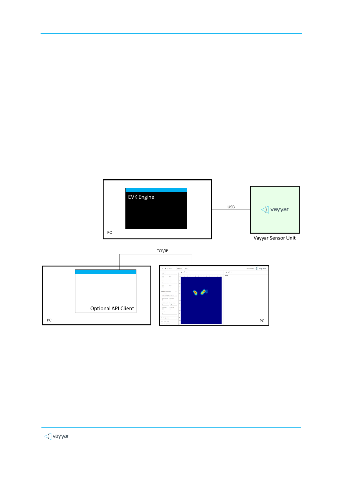
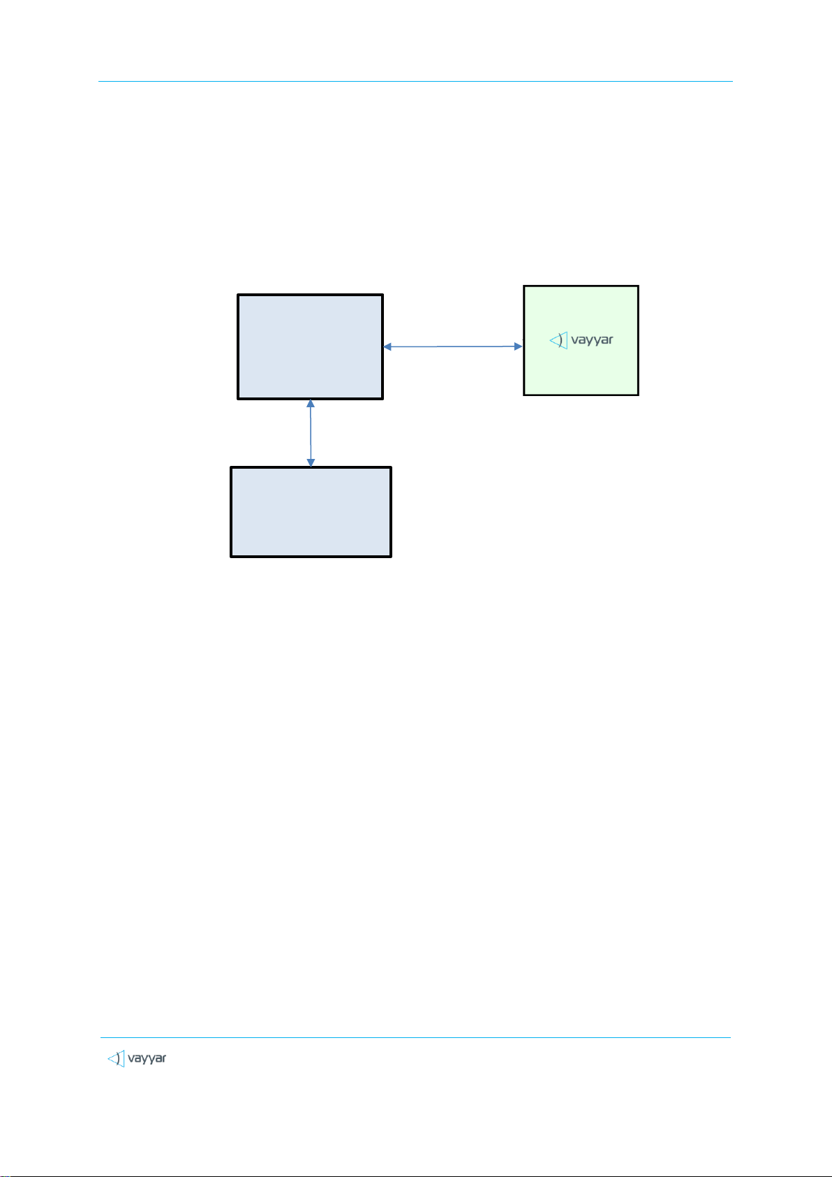
Models pertaining to the V60G-HOME-I family are intended to be integrated with an additional host,
either a PC-host operating the device through a USB interface, or a microcontroller-unit (MCU) for
integrated and embedded products.
The sensor detects objects in a defined arena and provides 3D-data of the targets to the host, such as:
position within the arena, class or posture; a raw 3D image (point-cloud for example).
Typical applications for the device can be touchless input device (e.g. gesture-recognition interface),
in-room people detection and monitoring for improving comfort and energy-utilization optimization
(e.g. HVAC operation and airflow optimization), detection of abnormal conditions such as fall of elderly
people and apnea in adults and babies, and in-cabin monitoring for detection of infants left in car.
The models participating in the V60G-HOME-I family (and certified under modular-approval) include,
but not limited to: vStraw_CTPB4_I, vBLU_OK_CTPB4, vBLU_MW_CTPB4.
1.1 Release Information Note
Software capabilities, algorithmic capabilities and different features are under continuous
development and improvement.
This document provides basic description of the system and it is operated. For more details –contact
Vayyar LTD through –www.vayyar.com.

V60G-HOME-I User Guide
Vayyar Confidential
Page 7 of 19
1.2 Glossary
Table 1: Glossary
Term
Definition
AC
Alternating Current
API
Application Programming Interface
DC
Direct Current
DLL
Dynamic Link Library
EVK
Evaluation Kit
GUI
Graphical User Interface
IP
Internet Protocol. An IP address is a numerical identifier assigned to a computing device or
node in a TCP/IP network. The address is used to locate and identify the node in
communications with other nodes on the network.
MCU
Micro-Controller Unit
PCB
Printed Circuit Board
RF
Radio Frequency
SoC
System-on-chip

V60G-HOME-I User Guide
Vayyar Confidential
Page 8 of 19
Chapter 2
System Overview
2.1 System Architecture
The V60G-HOME-I system may be operating with a host-PC and dedicated control and imaging SW
and GUI (for example an “EVK” architecture), or by running an imaging engine on a dedicated DSP
embedded into the proprietary VYYR7201_CTPB4 chips and using a dedicated API to extract the
processing outputs (“embedded architecture”), or any combination of the two.
An “EVK” architecture and connectivity scheme is illustrated in the figure below.
Figure 1: V60G-HOME-I “EVK” System Architecture
The “EVK” V60G-HOME-I system is comprised of the following components:
The V60G-HOME-I RF Sensor module.
The EVK Engine. Host software that performs signal processing functions. The software
runs in a command window in a PC, which is connected to the V60G-HOME-I Sensor via a
USB cable.

V60G-HOME-I User Guide
Vayyar Confidential
Page 9 of 19
Web GUI. User-interface client software that communicates with the EVK Engine via a
TCP/IP connection.
API Client. Optional, customer-developed software that communicates with the EVK
Engine via a TCP/IP connection.
A typical “Embedded” architecture is depicted in the following figure:
Figure 2: V60G-HOME-I “Embedded” System Architecture
Examples of used controllers may include EPS32, Raspberry-Pi CPU, etc.
Vayyar sensor module
Host Controller /
CPU
[Application]
SPI , USB
Central processing
unit \ server \ cloud
LAN \ WLAN \ Cellular

V60G-HOME-I User Guide
Vayyar Confidential
Page 10 of 19
2.2 Hardware
The figure below presents a high-level block diagram of the PCB that houses the USB-based sensor
unit:
Figure 3: High-Level Block Diagram –USB-based system
An SPI-based module is similar, excluding the USB-related components. The following components
are embedded in the sensor unit PCB:
Vayyar VYYR7201-B4 system-on-chip (SoC).
46 embedded Tx/Rx linear polarized PCB embedded, wide-band antennas.
A Crystal used as a clocking source for the Cypress MCU.
A TCXO (Temperature Compensated Crystal Oscillator) used as a clocking source for the
VYYR7201-B4 SoC.
Power supply system supporting 3.3V, 2.5V, 1.27V and 1.2V DC/DC converters.
For USB-based models - a digital interface that communicates with a host PC via a USB-2.0
connection. The interface is implemented using on-board Cypress micro-controller unit
(MCU).
For SPI-based models –the interface is communicating directly with VYYR7201- B4 SoC.

V60G-HOME-I User Guide
Vayyar Confidential
Page 11 of 19
2.2.1 Sensor Unit Specification
Table 2: Sensor Unit Specification
Parameter
Specification
Notes
Transceivers
24 Tx, 22 Rx
Frequency Band
Within 59 - 64 GHz
Or
61-61.5GHz
Configured by software.
Field of View (FoV)
Refer to section 2.2.5 Antenna and RF
Characteristics
Range Resolution
For example, for BW of 2GHz the
range-resolution is
Depends on the configured BW
Range Accuracy
< < Range Resolution
Depends on the target RCS
Angular Resolution
For example, for f= 64 GHz:
λ–Wavelength [@64GHz]
D –Length of the effective array [0.046m]
Angular Accuracy
<< Angular Resolution
Depends on the target strength and shape

V60G-HOME-I User Guide
Vayyar Confidential
Page 12 of 19
2.2.2 Digital Interface
The V60G-HOME-I models use either USB 2.0 or SPI as digital-interface, connecting the host module
to the sensor module.
The USB interface is implemented on the module using an MCU and a micro-USB connector. The SPI
interface is connected directly to the VYYR-7201-B4 chip, through a board-mounted multi-pin
connector.
Micro-Controller Unit (MCU)
Cypress’s EZ-USB FX3™ MCU integrates the USB 2.0 physical layers (PHYs), and contains a 32-bit
ARM926EJ-S microprocessor for building custom USB SuperSpeed applications. The integrated
processor contains a unit called General Programmable Interface (GPIF), which provides easy
connectivity to popular interfaces.
USB Connector
The onboard micro-USB-B 2.0 connector is used for power supply and for data transfer between the
sensor unit and the host PC. The connector supports the USB 2.0 protocol in High-Speed Mode (480
Mbps).
Figure 4: vStraw_CTPB4_I Connectivity
SPI Interface
Modules which are using SPI interface, the digital-interfaces and power supply are fed through a
dedicated connector. The exact connector used changes per specific model, for example
VBLUOK_CTPB4 uses OK-06F030-04.

V60G-HOME-I User Guide
Vayyar Confidential
Page 13 of 19
Figure 5: vBLU_OK _CTPB4 connector
The exact pinout is provided with the module itself and a reference design.
2.2.3 RF Interface - Antennas
The array of 46 antennas serves to connect the sensor unit with the environment. The antennas are
embedded in the PCB, as depicted in the figure below.
Figure 6: Antenna Positions and Numbering
For each transmitting (TX) antenna, there are multiple receiving (RX) antennas for collecting and
recording the received RF signals. Each RX antenna and its associated TX antenna serve as an
antenna pair.
All 46 antennas are from the same antenna type, which is linear polarized PCB embedded, wide-
band antennas.
2.2.4 Electrical Specifications
The following electrical specifications are for the sensor unit. The current consumption specifications
are based on lab measurements performed by Vayyar.

V60G-HOME-I User Guide
Vayyar Confidential
Page 14 of 19
Table 3: Sensor Unit Electrical Specification
Parameter
Value
Vcc supply voltage
5 VDC
Max current consumption
~1.6 A
Average current consumption
~0.75 A
2.2.5 Antenna and RF Characteristics
The following are antenna and RF characteristics, based on the simulation of a single antenna over
an infinite ground plane:
Table 4: Antenna and RF Characteristics
Parameter
Value
Comment
Gain
~ 5 dBi @62 GHz
At 0˚ Elevation, 0˚ Azimuth
Antenna -5dB beamwidth
160 deg. @64 GHz (E-plane)
80 deg. @64 GHz (H-plane)
Polarization
Linear
Max Tx Power
8 dBm
On chip output.
Configurable (typically lower to meet
FCC requirements)
The figure below depicts an antenna and its E and H planes:
E-plane –plane XZ (green)
H-plane –plane YZ (red)
Figure 7: V60G-HOME-I Antenna Pattern

V60G-HOME-I User Guide
Vayyar Confidential
Page 15 of 19
2.3 Software
The V60G-HOME-I system software performs signal processing and generation of the arena image,
either on a host-device, or on an embedded DSP processor.
The software generates a 3D image and a point-cloud corresponding to the detected objects in the
arena, and may extract further details through more advanced algorithms (for example –fall-
detection, breathing waveform monitoring etc). The data can be obtained either using a dedicated
API (see detailed module SW manual), or a Graphical User Interface (GUI).
The following diagram describes a typical processing flow of the software.
Figure 8: Processing Flow
Signal
transmission
Signal received
and recorded
Image
reconstruction
Post-
processing
Data
presentation /
extraction
Data save to
files (optional)

V60G-HOME-I User Guide
Vayyar Confidential
Page 16 of 19
Chapter 3
Regulatory section
3.1 Compliance
3.1.1 FCC
The device is certified under FCC part 15 section 15.255, as - FCC-ID : 2AHIS-V60G-HOME-I.
This V60G-HOME-I device has been tested and found to comply with the limits for a Class B digital
device, pursuant to Part 15 of the FCC Rules. These limits are designed to provide reasonable
protection against harmful interference in a residential installation. This equipment generates uses
and can radiate radio frequency energy and, if not installed and used in accordance with the
instructions, may cause harmful interference to radio communications. However, there is no
guarantee that interference will not occur in a particular installation. If this equipment does cause
harmful interference to radio or television reception, which can be determined by turning the
equipment off and on, the user is encouraged to try to correct the interference by one of the
following measures:
Reorient or relocate the receiving antenna.
Increase the separation between the equipment and receiver.
Connect the equipment into an outlet on a circuit different from that to which the receiver is
connected. Consult the dealer or an experienced radio/TV technician for help.
Changes or modifications not expressly approved by the party responsible for compliance could void
the user's authority to operate the equipment.
The device shall not be used on an airplane while airborne.
This device complies with Part 15 of the FCC Rules.
Operation is subject to the following two conditions:
(1) This device may not cause harmful interference, and
(2) This device must accept any interference received, including interference that may cause
undesired operation.

V60G-HOME-I User Guide
Vayyar Confidential
Page 17 of 19
3.1.2 IC
Industry Canada ICES-003 Compliance: CAN ICES-3 (B)/NMB-3(B)
IC Caution: RSS-Gen Issue 4 December 2014”&”CNR-Gen 4e Décembre 2014:
- English:
This device complies with Industry Canada licence-exempt RSS standard(s).
Operation is subject to the following two conditions: (1) This device may not cause
interference, and (2) This device must accept any interference, including interference
that may cause undesired operation of the device.
- French:
Le présent appareil est conforme aux CNR d’Industrie Canada applicables aux
appareils radio exempts de licence. L’exploitation est autorisée aux deux conditions
suivantes:
(1) l’appareil ne doit pas produire de brouillage, et;
(2) l’utilisateur de l’appareil doit accepter tout brouillage radioélectrique subi, même
si le brouillage est susceptible d’encompromettre le fonctionnement.
IC: 21498-V60GHOMEI.

V60G-HOME-I User Guide
Vayyar Confidential
Page 18 of 19
3.2 Instructions for the Integrator
The OEM integrator is responsible for ensuring that the end-user has no manual instructions to
remove or install module.
3.2.1 OEM Integrators Notices
This device is intended only for OEM integrators under the following conditions:
The transmitter module may not be co-located with any other transmitter or antenna. As long as this
condition above is met, further transmitter testing will not be required. However, the OEM
integrator is still responsible for testing their end-product for any additional compliance
requirements required with this module installed.
IMPORTANT NOTE: In the event that this condition cannot be met (for example certain laptop
configurations or co-location with another transmitter), then the FCC/ISED authorization is no longer
considered valid and the FCC ID/IC number cannot be used on the final product. In these
circumstances, the OEM integrator will be responsible for re-evaluating the end product (including
the transmitter) and obtaining a separate FCC/ISED authorization.
3.2.2 End Product Labeling
Visible area with the following: “Contains FCC ID: 2AHIS-V60G-HOME-I” and “Contains IC ID: 21498-
V60GHOMEI”(either in user-manual, on the package or the product case).
When the hosting device uses an electric-display in a product, it should be possible to display
electronically the FCC-ID.
3.2.3 OEM Manual Information that Must be Included
The OEM integrator has to be aware not to provide information to the end user regarding how to
install or remove this RF module in the user manual of the end product which integrates this
module.
The user manual for OEM integrators must include the following information in a prominent
location:
IMPORTANT NOTE: To comply with FCC/ISED RF exposure requirements, this device and its antennas
must not be co-located or used in conjunction with any other antenna or transmitter except under
the conditions shown in the FCC/ISED filing and/or in accordance with FCC/ISED multi-transmitter
product guidelines.

V60G-HOME-I User Guide
Vayyar Confidential
Page 19 of 19
3.2.4 RF Exposure Guidance
In order to comply with FCC / ISED RF Exposure requirements, this device must be installed to
provide at least 20 cm separation from the human body at all times.
“Afin de se conformer aux exigences d'exposition RF FCC / ISED, cet appareil doit être installé pour
fournir au moins 20 cm de séparation du corps humain en tout temps.“
END OF DOCUMENT
This manual suits for next models
1
Table of contents
Popular Control Unit manuals by other brands

Festo
Festo EHMD-40-RE Series Instructions for use

FAAC
FAAC MASTER-T manual

IBP
IBP HDC75 Quick start guide and safety instructions

Hydra-Stop
Hydra-Stop Insta-Valve 250 Patriot installation instructions

DEKA Controls
DEKA Controls SureStart HSS-32A1 Operating instruction

M-system
M-system R7M-EC8A/UL instruction manual