Vdwall A65 User manual

SHENZHEN VDWALL CO., LTD www.videowall.cn
ADD: Room 1001,10th Floor, Tower 4, Fangda-City, Longzhu 4th Road,
Nanshan District, Shenzhen, China TEL: 0755-26750210
_________________________________________________________________________________A65 User Quick Setup Guide
1
A65 User Quick Setup Guide
SHENZHEN VDWALL CO., LTD
2020.04

SHENZHEN VDWALL CO., LTD www.videowall.cn
ADD: Room 1001,10th Floor, Tower 4, Fangda-City, Longzhu 4th Road,
Nanshan District, Shenzhen, China TEL: 0755-26750210
_________________________________________________________________________________A65 User Quick Setup Guide
2
1. Front Panel Button
Input Signal Selection
Menu Setup
Source Card Selection
DVI Output Selection
Display Mode Button

SHENZHEN VDWALL CO., LTD www.videowall.cn
ADD: Room 1001,10th Floor, Tower 4, Fangda-City, Longzhu 4th Road,
Nanshan District, Shenzhen, China TEL: 0755-26750210
_________________________________________________________________________________A65 User Quick Setup Guide
3
Category
Button
Description
Input Signal
Selection Button
HDMI1、HDMI2、DP-1、
DP-2、HDMI-3、SDI、
HDMI-7、CVBS
A65 built in 3 input cards,identified as:In-A、In-B、In-C. In-A can access in 4K or 2K
signal,In-B only support 4K2K signal,In-C support 2K signal. Press signal button directly
to select signal channel for each input card, if selected signal is valid, button indicator will
light up, or else flicker. Press VGA button of In-C to automatically calibrate VGA signal.
In-C/PIP
In-C provides PIP/POP dual image display. Press this button, button indicator light up,
PIP/POP function will be activated,henceforth select sub-Image source
Source Card
Selection Button
In-A、In-B、In-C
Source card selection button. Press this button to switch A65 signal source card,
corresponding button indicator will light up.
DVI Output Port
Switch Button
DVI-Out
In menu setup, press this button to switch DVI output port. When A65 in Cascading mode,
If slave A65 Genlock signal locked, button indicator light up, or else flicker.
Lock
Info Button
Lock
Button lock. Press this button directly, button indicator will light up, all button on front panel
will be invalid, except Lock button itself, so as to avert misoperation. Press this button 3
times continually to exit button lock mode, button indicator will light off.
Info
Information button,press this button to check A65 setup information and firmware version,
press continually to turn page

SHENZHEN VDWALL CO., LTD www.videowall.cn
ADD: Room 1001,10th Floor, Tower 4, Fangda-City, Longzhu 4th Road,
Nanshan District, Shenzhen, China TEL: 0755-26750210
_________________________________________________________________________________A65 User Quick Setup Guide
4
Category
Button
Description
Menu Setup
Button
Setup
Menu setup button. A65 in operation mode, press this button to enter menu setup
Ok
Knob or OK button, rotate this button to adjust setup value, press this button to save or
apply configuration
Up and Down selection button. A65 in configuration mode, press this button to select
menu item. In operation mode, press this button directly to adjust output image brightness
Return or Exit button. Press this button to exit present setup and return to previous setup
menu, until A65 enter operation mode
Display Mode
Selection Button
DM-1、DM-2、DM-3
Display mode selection button. Display mode can preset size&position of input and output
signal. Press DM-1、DM-2、DM-3 directly to recall different display mode; in menu setup,
press DM-1、DM-2、DM-3 to select target display mode for parameter saving
DM+
More display mode selection button. A65 provides 16 preset display mode,identified as:
DM1、DM2、DM3、DM4、DM5、DM6、DM7、DM8、DM9、DM10、DM11、DM12、
DM13、DM14、DM15、DM16. the last 3 display mode for backup usage, can’t be modified
or recalled directly. Press ↑、↓button to select different display mode,press OK button to
confirm and apply

SHENZHEN VDWALL CO., LTD www.videowall.cn
ADD: Room 1001,10th Floor, Tower 4, Fangda-City, Longzhu 4th Road,
Nanshan District, Shenzhen, China TEL: 0755-26750210
_________________________________________________________________________________A65 User Quick Setup Guide
5
2. Rear Panel Port Description
1)Input Signal Port
A65 provides 3 input card:
In-A is 4K input card,provides HDMI2.0×2 and DP1.2×1,can access in 4K2K_60Hz UHD signal or 2K HD signal
In-B is also 4K input card,offers HDMI2.0×1 and DP1.2×1,only support 3840*2160_60/50/30/25/24 Hz UHD signal
In-C is 2K input card,including CVBS×1、3G-SDI×1、HDMI(DVI / VGA)×1 ,HDMI version is HDMI1.3. HDMI port compatible with
DVI and VGA signal,when plug in VGA signal,set the DIP switcher to VGA side
GenLock Port
Control Port
DVI Output Port
Input Port

SHENZHEN VDWALL CO., LTD www.videowall.cn
ADD: Room 1001,10th Floor, Tower 4, Fangda-City, Longzhu 4th Road,
Nanshan District, Shenzhen, China TEL: 0755-26750210
_________________________________________________________________________________A65 User Quick Setup Guide
6
2)DVI Output Port
A65 built in 1 output card,allow 4 DVI splicing. Default output resolution is 1920*1080_60Hz,user defined output resolution available
3)Communication Control Port
LAN:TCP / IP network control
USB and RS232 control
4)GenLock Cascading Port
A65 provides multiple device cascading,so as to extend input and output resolution
When A65 operating as slave processor, GenLock In port receive command signal from master A65 GenLock Out port,
so forth realize completely synchronized splicing
Single A65 offers Out-1、Out-2、Out-3、Out-4 total 4 GenLock output port,support 5 A65 cascading

SHENZHEN VDWALL CO., LTD www.videowall.cn
ADD: Room 1001,10th Floor, Tower 4, Fangda-City, Longzhu 4th Road,
Nanshan District, Shenzhen, China TEL: 0755-26750210
_________________________________________________________________________________A65 User Quick Setup Guide
7
3. A65 Image Processing Procedure
S1: Input signal selection
1 from 3
1 from 2
4K input
In-A
HDMI-1
HDMI-2
DP-1
4K input
In-B
HDMI-3
DP-2
DP-Loop
2K input
In-C
HDMI-1
CVBS-1
SDI-1
1 from 3
2 from 3
Via PIP
S2: Source selection
3:1
1 from 3
S4: Output image setup
DVI-1
DVI-4
Output processing:Genuine 4k2K_60Hz
S3: Image cropping of input signal
3840
2160

SHENZHEN VDWALL CO., LTD www.videowall.cn
ADD: Room 1001,10th Floor, Tower 4, Fangda-City, Longzhu 4th Road,
Nanshan District, Shenzhen, China TEL: 0755-26750210
_________________________________________________________________________________A65 User Quick Setup Guide
8
Description:
1)A63 image processing procedure is divided into 4 main steps:
S1:Input signal selection
S2:Source card selection
S3:Image cropping of input signal
S4:Output image size&position setup
2)Input signal selection(S1)
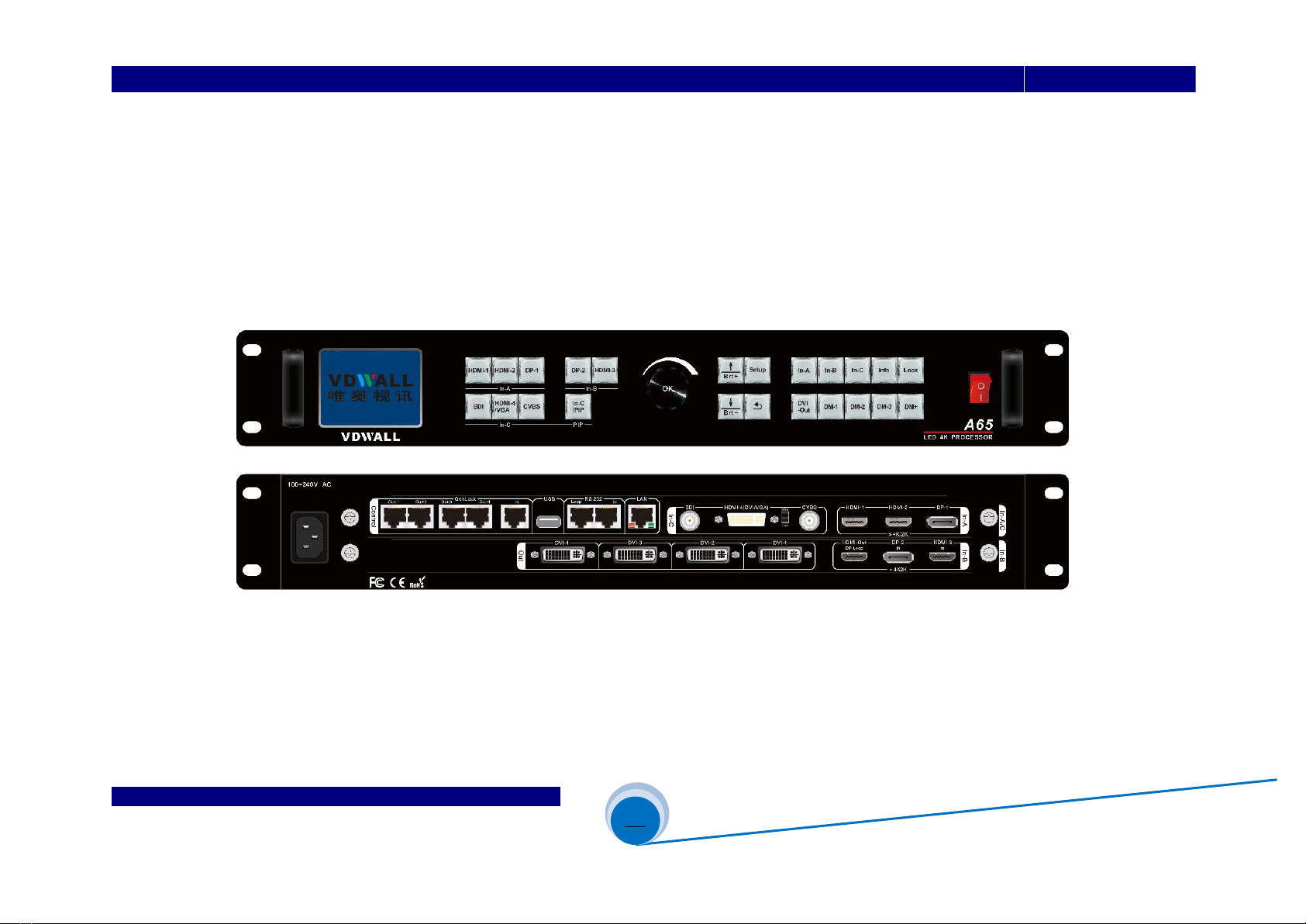
2.1)A65 built in 3 input cards,including:
4K input card:In-A
4K direct input card:In-B
2K input card:In-C
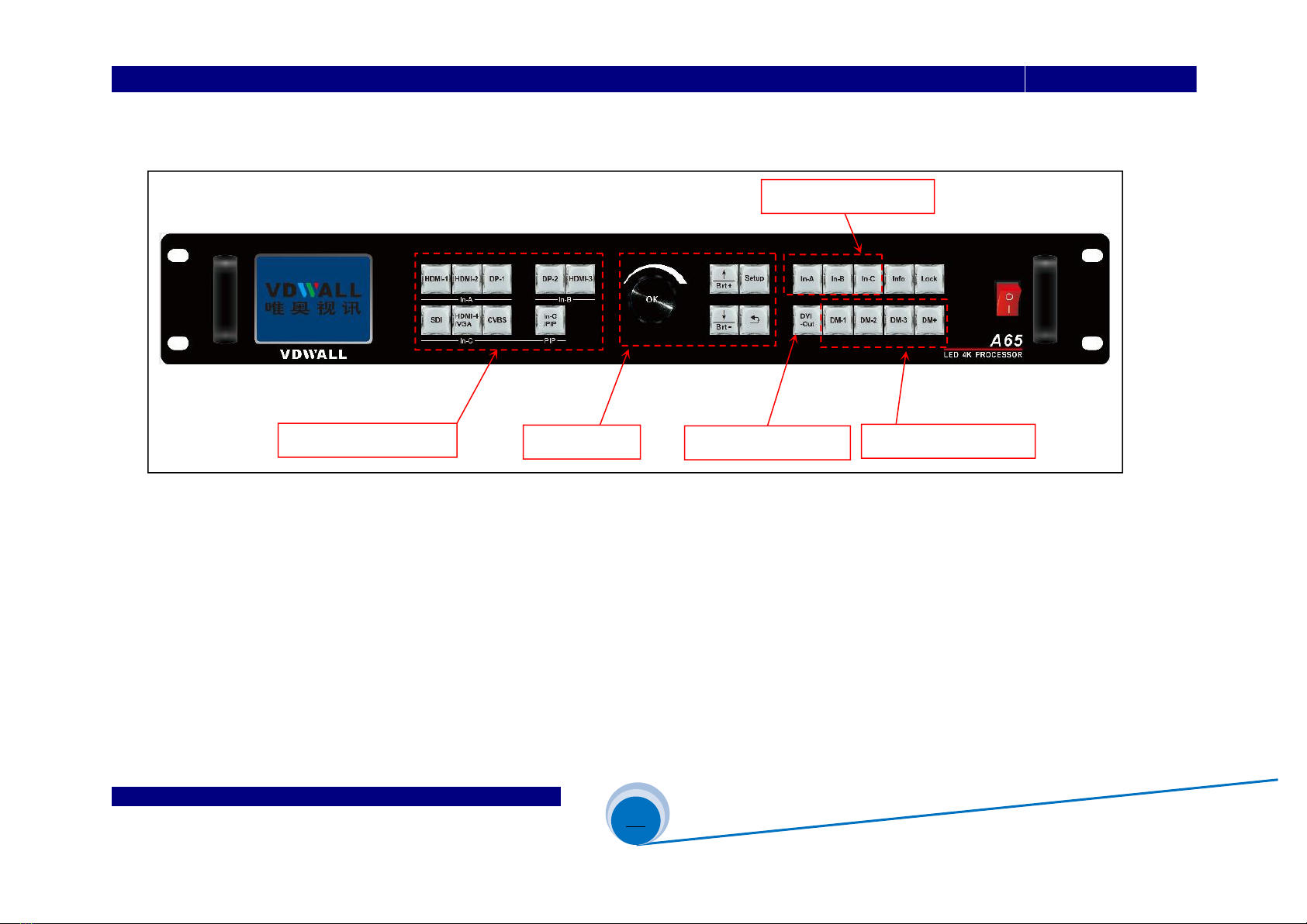
2.2)In-A support 4K or 2K signal,select signal channel from HDMI-1、HDMI-2 or DP-1
2.3)In-B is 4K direct input card,can only access in 3840×2160_60Hz/50 Hz/30 Hz/25Hz/24Hz/23Hz standard 4K signal.
Select signal channel from HDMI-3 or DP-2
2.4)In-C is 2K input card,select signal from SDI-1、HDMI-6 or CVBS-1. On condition PIP-C function activated,
user can select the other sub image source
2.5)Press front panel button directly to select signal channel for each input card

SHENZHEN VDWALL CO., LTD www.videowall.cn
ADD: Room 1001,10th Floor, Tower 4, Fangda-City, Longzhu 4th Road,
Nanshan District, Shenzhen, China TEL: 0755-26750210
_________________________________________________________________________________A65 User Quick Setup Guide
9
3)Source card selection(S2)
3.1)A65 select signal source from In-A、In-B or In-C card
3.2)Press In-A、In-B or In-C button to select source card,button indicator will light up
4)Image cropping of input signal (S3)
4.1)A65 offers 4 DVI output
4.2)Each DVI can display whole or partial 3840×2160 image,as S3 show,the image in dotted frame
5)Output image size&position setup(S4)
5.1)Each DVI can display cropped content (Finished in step 4.2) in any size and position

SHENZHEN VDWALL CO., LTD www.videowall.cn
ADD: Room 1001,10th Floor, Tower 4, Fangda-City, Longzhu 4th Road,
Nanshan District, Shenzhen, China TEL: 0755-26750210
_________________________________________________________________________________A65 User Quick Setup Guide
10
4. Adjustment And Setup
Step1:Input And Output Connection
1.1)Plug input signal cable to A65
1.2)Connect DVI output to sending card or LCD
1.3)Usually,solution diagram as Figure 4-1:
Figure 4-1

SHENZHEN VDWALL CO., LTD www.videowall.cn
ADD: Room 1001,10th Floor, Tower 4, Fangda-City, Longzhu 4th Road,
Nanshan District, Shenzhen, China TEL: 0755-26750210
_________________________________________________________________________________A65 User Quick Setup Guide
11
Step2 :Power On、Set Output Resolution
2.1)A65 power on,wait for boot up
2.2)As Figure4-3,LCD boot up interface
2.3)In-A select HDMI1 input
In-B select HDMI3 input
In-C PIP activated, main image source HDMI4,sub-image SDI
If selected signal valid, button indicator on, or else flicker
2.4)Source card is In-C
2.5)Current display mode DM1
2.6)In operation mode,press Setup enter A65 menu setup,
Press ↑、↓and OK button,enter menu“ 5.1 Out Res.”,
rotate Knob to select target output resolution. Press ↓
button,select“5.2 Init Data”,press OK to confirm and apply,
A65 will automatically reboot and apply the new output resolution
Figure 4-2
Figure 4-3
In-A:HDMI1
In-B:HDMI3
In-C:HDMI4 PIP:SDI
--------------------------------------
Output Mode: DM1
Input Source: In-C
Out Port: DVI4
In Pos.&Size: (0,3840,0,2160)
Out Pos.&Size: (0,1920,0,1080)
5. System
-------------------------------------
5.1 Output Res. 1920×1080_60 Hz
5.2 Init Data Press <OK> to apply
-------------------------------------

SHENZHEN VDWALL CO., LTD www.videowall.cn
ADD: Room 1001,10th Floor, Tower 4, Fangda-City, Longzhu 4th Road,
Nanshan District, Shenzhen, China TEL: 0755-26750210
_________________________________________________________________________________A65 User Quick Setup Guide
12
Step3 :Select Signal Channel For Each Input Card
3.1)Press front panel button to select input signal
3.2)If selected signal is valid, button indicator light up, or else flicker
3.3)As Figure4-4,A65 LCD shows source card In-C
3.4)Press In-C/PIP button to activate In-C PIP/POP function,hence select the other sub-image source
Step4:Select Source Card
4.1)In operation mode,press In-A、In-B or In-C to select source card,
button indicator will light up
4.2)A65 only display one source card image at one time,
LCD interface as Figure4-4
Figure 4-4
In-A:HDMI1
In-B:HDMI3
In-C:HDMI4
--------------------------------------
输出卡模式: DM1
输入信号源: In-C
输出口: DVI4
输入位置大小: (0,3840,0,2160)
输出位置大小: (0,1920,0,1080)
In-A:HDMI1
In-B:HDMI3
In-C:HDMI4 PIP:SDI
--------------------------------------
Output Mode: DM1
Input Source: In-C
Out Port: DVI4
In Pos.&Size: (0,3840,0,2160)
Out Pos.&Size: (0,1920,0,1080)
Source Card

SHENZHEN VDWALL CO., LTD www.videowall.cn
ADD: Room 1001,10th Floor, Tower 4, Fangda-City, Longzhu 4th Road,
Nanshan District, Shenzhen, China TEL: 0755-26750210
_________________________________________________________________________________A65 User Quick Setup Guide
13
Step5:Input Source Image Cropping
5.1)A65 provides 4 DVI splicing,each DVI support random
size&position cropping of input 3840*2160 image.
As Figure 4-5, DVI-1 display cropped image in red
dotted frame, DVI 4 display cropped image in blue
dotted frame
5.2)The size&position of cropped image is defined by the
following 4 parameters
Input width (In_Width)
Input horizontal start (In_H_Start)
Input height (In_Height)
Input vertical start (In_V_Start)
5.3)Enter menu “3.2 Manual Mosaic”:
5.3.1)Select display mode for parameter saving,
press DM1、DM2、DM3 or DM+ to select target
display mode
5.3.2)Select DVI output port that need configure,
press DVI-Out button to shift DVI output
(0, 0)
Win-1
3840
2160
DVI-1
DVI-4
In_H_Star
In_H_Star
In_Width
In_Height
图4-5
Figure 4-5

SHENZHEN VDWALL CO., LTD www.videowall.cn
ADD: Room 1001,10th Floor, Tower 4, Fangda-City, Longzhu 4th Road,
Nanshan District, Shenzhen, China TEL: 0755-26750210
_________________________________________________________________________________A65 User Quick Setup Guide
14
As Figure 4-6:In DM1, DVI1 Manual Mosaic parameters
5.3.3)The cropped image displayed by DVI 1 is defined by the following
parameters:
“ 3.2.1 In Width ”
“ 3.2.2 In H_Start ”
“ 3.2.3 In Height ”
“ 3.2.4 In V_Start ”
Press ↑、↓button select item,rotate Knob to adjust value,
press OK button to save and apply
5.4)Please refer to《Appendix 1》for detailed description of manual mosaic
Figure 4-6
3.2 Manual Mosaic DM1/DVI1
--------------------------------------
3.2.1 In Width 3840 3840
3.2.2 In H_Start 0 0
3.2.3 In Height 2160 2160
3.2.4 In V_Start 0 0
3.2.5 Out Width 1920 1920
3.2.6 Out H_Start 0 0
3.2.7 Out Height 1080 1080
3.2.8 Out V_Start 0 0
--------------------------------------

SHENZHEN VDWALL CO., LTD www.videowall.cn
ADD: Room 1001,10th Floor, Tower 4, Fangda-City, Longzhu 4th Road,
Nanshan District, Shenzhen, China TEL: 0755-26750210
_________________________________________________________________________________A65 User Quick Setup Guide
15
Step6:Set Size&Position Of Output Image
6.1)A65 4 DVI output ports can randomly size
and position image within output resolution.
For instance, output resolution is 1920×1080@60Hz,
user can assign output image at any size&position in
range of 1920×1080
6.2)Refer to Figure 4-7, the picture in red dotted frame
is DVI-1 output image,defined by the following
4 parameters:
Output width (Out_Width)
Output horizontal start(Out_H_Start)
Output height (Out_Height)
Output vertical start (Out_V_Start)
6.3)Enter menu “3.2 Manual Mosaic”:
6.3.1)Select display mode for parameter saving
Press DM1、DM2、DM3 or DM+ to select target
display mode
6.3.2)Press DVI-Out button to select target DVI output port
(0,
OUT-B / DVI-4
Win-1
3840
2160
(0,
DVI-1
1920
1080
Out_H_Sta
Out_V_Star
Out_Height
Out_Width
图4-7
Figure 4-7

SHENZHEN VDWALL CO., LTD www.videowall.cn
ADD: Room 1001,10th Floor, Tower 4, Fangda-City, Longzhu 4th Road,
Nanshan District, Shenzhen, China TEL: 0755-26750210
_________________________________________________________________________________A65 User Quick Setup Guide
16
As Figure 4-8:Set DVI-1 output image size&position in DM1
6.3.3)Selected DVI output image size&position is defined by the
following 4 parameters:
“ 3.2.5 Out Width ”
“ 3.2.6 Out H_Start ”
“ 3.2.7 Out Height ”
“ 3.2.8 Out V_Start ”
Press ↑、↓select menu item,rotate Knob to adjust value,
press OK to save and apply parameters
6.4)Usually the sending card default start point(x,y) is (0,0)
So processor default output start point:
Out H_Start = 0
Output V_Start = 0
Output Width = LED actual pixels in horizontal
Output Height = LED actual pixels in vertical
Figure 4-8
3.2 Manual Mosaic DM1/DVI1
--------------------------------------
3.2.1 In Width 3840 3840
3.2.2 In H_Start 0 0
3.2.3 In Height 2160 2160
3.2.4 In V_Start 0 0
3.2.5 Out Width 1920 1920
3.2.6 Out H_Start 0 0
3.2.7 Out Height 1080 1080
3.2.8 Out V_Start 0 0
--------------------------------------

SHENZHEN VDWALL CO., LTD www.videowall.cn
ADD: Room 1001,10th Floor, Tower 4, Fangda-City, Longzhu 4th Road,
Nanshan District, Shenzhen, China TEL: 0755-26750210
_________________________________________________________________________________A65 User Quick Setup Guide
17
Fast Mosaic
1)Fast Mosaic is calculation added splicing method. Compare to Manual Mosaic
Fast Mosaic more intuitive and convenient
2)As figure 4-9,the LED is composed of 4 unit screen,each unit screen
resolution as following table
LED1
1728×1056
LED2
1824×1056
LED3
1728×960
LED4
1824×960
LED total resolution:3552×2016
3)Use A65 4 DVI output to drive 4 unit screen, connection as following table:
DVI-1
LED1
DVI-2
LED2
DVI-3
LED3
DVI-4
LED4
4)Enter menu“ 3.1 Fast Mosaic”,configure each DVI accordingly,as Figure 4-10 、Figure 4-11 、Figure 4-12 、4-13
5)In Fast Mosaic setup,the top left coordinate is(0,0), calculate each unit screen coordinate accordingly
6)After configure menu item 3.1.1---3.1.7,press ↓button to “3.18 Auto Calculation” , press OK to apply,then
press DVI-Out button to shift DVI output port
7)After fast mosaic, if need fine tuning of mosaic parameters, enter menu “3.2 Manual Mosaic”
LED1= 1824×1056
LED2 = 1728×1056
LED3 = 1824×960
LED4 = 1728×960
1728
1824
3552
1056
960
2016
(0,0)
(1728,0)
(0,960)
(1728,960)
Figure4
Figure 4-9

SHENZHEN VDWALL CO., LTD www.videowall.cn
ADD: Room 1001,10th Floor, Tower 4, Fangda-City, Longzhu 4th Road,
Nanshan District, Shenzhen, China TEL: 0755-26750210
_________________________________________________________________________________A65 User Quick Setup Guide
18
Figure 4-11
3.1 Fast Mosaic DM1/DVI2
-------------------------------------------
3.1.1 LED Panel Panel
3.1.2 LED Total Width 3552
3.1.3 LED Total Height 2016
3.1.4 Unit Width 1824
3.1.5 Unit Height 1056
3.1.6 Unit H_Start 1728
3.1.7 Unit V_Start 0
3.1.8 Auto Calculation OK To Apply
--------------------------------------
Figure 4-10
3.1 Fast Mosaic DM1/DVI1
-------------------------------------------
3.1.1 LED Panel Panel
3.1.2 LED Total Width 3552
3.1.3 LED Total Height 2016
3.1.4 Unit Width 1728
3.1.5 Unit Height 1056
3.1.6 Unit H_Start 0
3.1.7 Unit V_Start 0
3.1.8 Auto Calculation OK To Apply
--------------------------------------
Figure 4-12
3.1 Fast Mosaic DM1/DVI3
-------------------------------------------
3.1.1 LED Panel Panel
3.1.2 LED Total Width 3552
3.1.3 LED Total Height 2016
3.1.4 Unit Width 1728
3.1.5 Unit Height 960
3.1.6 Unit H_Start 0
3.1.7 Unit V_Start 1056
3.1.8 Auto Calculation OK To Apply
--------------------------------------
Figure 4-13
3.1 Fast Mosaic DM1/DVI4
-------------------------------------------
3.1.1 LED Panel Panel
3.1.2 LED Total Width 3552
3.1.3 LED Total Height 2016
3.1.4 Unit Width 1824
3.1.5 Unit Height 960
3.1.6 Unit H_Start 1728
3.1.7 Unit V_Start 1056
3.1.8 Auto Calculation OK To Apply
--------------------------------------

SHENZHEN VDWALL CO., LTD www.videowall.cn
ADD: Room 1001,10th Floor, Tower 4, Fangda-City, Longzhu 4th Road,
Nanshan District, Shenzhen, China TEL: 0755-26750210
_________________________________________________________________________________A65 User Quick Setup Guide
19
Appendix 1:How To Manually Calculate Mosaic Parameters
Ap1.1)As Figure Ap1-1, need A65 display AP1-1 image on AP1-2 LED,
A65 4 DVI output jointly drive the screen
Ap1.2)Calculate each DVI input and output parameters correctly,
so as to guarantee display effect
Ap1.3)A65 “3.1 Fast Mosaic” can conveniently
calculate input and output parameters
Ap1.4)On some special occasions, we may use “ 3.2 Manual Mosaic ”
to calculate mosaic parameters.
As the below formula
so:Y1=(2160×1056)÷2016=1131
similarly:
then:X1=(3840×1728)÷3552=1868
Finally we secure the parameters as below:
Y1=1131 Y2=2019
X1=1868 X2=1972
Figure
LED1 = 1728×1056
LED2 = 1824×1056
LED3 = 1728×960
LED4 = 1824×960
1056
960
2016
(0,0)
(3648,0)
(0,960)
(3648,960)
1728
1824
3552
Figure
Win-1
3840
2160
(0,
Y1=1131
Y2=1029
X2=1972
X1=1868
Figure AP1-2
X1
=
1728
3840
3552
Y1
=
1056
2160
2016
Figure AP1-1

SHENZHEN VDWALL CO., LTD www.videowall.cn
ADD: Room 1001,10th Floor, Tower 4, Fangda-City, Longzhu 4th Road,
Nanshan District, Shenzhen, China TEL: 0755-26750210
_________________________________________________________________________________A65 User Quick Setup Guide
20
Ap1.5)Finally,we obtain the manual mosaic parameters as following table:
DVI-1
DVI-2
DVI-3
DVI-4
LED1
LED2
LED3
LED4
3.2.1 In Width
1868
1972
1868
1972
3.2.2 In H_Start
0
1868
0
1868
3.2.3 In Height
1131
1131
1029
1029
3.2.4 In V_Start
0
0
1131
1131
3.2.5 Out Width
1728
1728
1824
1824
3.2.6 Out H_Start
0
0
0
0
3.2.7 Out Height
1056
1056
960
960
3.2.8 Out V_Start
0
0
0
0
Other manuals for A65
1
Table of contents
Other Vdwall Media Converter manuals

Vdwall
Vdwall LVP609 Series Instruction manual

Vdwall
Vdwall LVP909 Series User manual

Vdwall
Vdwall SC-12 User manual

Vdwall
Vdwall LVP615 series Instruction manual

Vdwall
Vdwall LVP609 Series User manual

Vdwall
Vdwall LVP615 series User guide

Vdwall
Vdwall LedSync820C User manual

Vdwall
Vdwall DS2-4 Operational manual

Vdwall
Vdwall LVP615S User manual

Vdwall
Vdwall LVP615S User manual