Vecow MTC-2021 User manual

USER
Manual
USER
Manual
1.0.0 Edition 20150324
MTC-2021
21.5” Fanless Multi-Touch Computer

ii
Version Date Page Description Remark
0.9 03/06/2015 All Preliminary Release
1.0 03/24/2015 All Ofcal Release
Record of Revision

iii
This manual is released by Vecow Co., Ltd. for reference purpose only. All
product offerings and specications are subject to change without prior notice. It
does not represent commitment of Vecow Co., Ltd. Vecow shall not be liable for
direct, indirect, special, incidental, or consequential damages arising out of the
use of the product or documentation, nor for any infringements upon the rights
of third parties, which may result from such use.
This equipment has been tested and found to comply with the limits for a Class
A digital device, pursuant to part 15 of the FCC Rules. These limits are designed
to provide reasonable protection against harmful interference when the
equipment is operated in a commercial environment. This equipment generates,
uses, and can radiate radio frequency energy and, if not installed and used in
accordance with the instruction manual, may cause harmful interference to radio
communications. Operation of this equipment in a residential area is likely to
cause harmful interference in which case the user will be required to correct the
interference at his own expense.
FCC
The product (s) described in this manual complies with all applicable European
Union (CE) directives if it has a CE marking. For computer systems to
remain CE compliant, only CE-compliant parts may be used. Maintaining CE
compliance also requires proper cable and cabling techniques.
CE
This document contains proprietary information protected by copyright. No part
of this publication may be reproduced in any form or by any means, electric,
photocopying, recording or otherwise, without prior written authorization
by Vecow Co., Ltd. The rights of all the brand names, product names and
trademarks belong to their respective owners.
Declaimer
Declaration of Conformity
Copyright and Trademarks

iv
Part Number Description
MTC-2021 21.5” Fanless Multi-Touch Computer with Intel®Bay Trail
Quad-Core E3845 Processor
Order Information
Part Number Description
DDR3L8G Certied DDR3L 8G RAM
DDR3L4G Certied DDR3L 4G RAM
PWA-60WP3B 60W, 24V/2.5A 100V AC to 240V AC Power Adapter for 3 Pin 5.0mm
Terminal Block
Panel-Mount Panel mount Kit
VESA-Mount VESA Table Stand
WiFi Module Mini PCIe WiFi Module with Antenna
3G Module Mini PCIe 3G/GPS Module with Antenna
4G Module Mini PCIe 4G/GPS Module with Antenna
Order Accessories

v
Table of Contents
CHAPTER 1 GENERAL INTRODUCTION 1
1.1 Overview 1
1.2 Features 1
1.3 Product Specication 2
1.4 Mechanical Dimension 4
CHAPTER 2 GETTING TO KNOW YOUR MTC-2021 5
2.1 Packing List 5
2.2 I/O Functions 6
2.2.1 External I/O Connectors 6
2.2.2 Reset Tact Switch 6
2.2.3 Power Button 7
2.2.4 PWR & HDD LED Indicators 7
2.2.5 VGA Connector 8
2.2.6 HDMI Connector 9
2.2.7 Dual USB 2.0 9
2.2.8 10/100/1000 Mbps LAN Port 10
2.2.9 Audio Connector 11
2.2.10 8-bit GPIO 11
2.2.11 Serial Port COM 1/ COM 2 12
2.2.12 Serial Port COM 3/ COM 4 13
2.2.13 Isolated Serial Port COM 5/ COM 6 14
2.2.14 DC-in 9V to 28V Terminal Block 15
2.2.15 USB 3.0 Ports 15
2.3 Mainboard Expansion Connector 16
2.3.1 Panel Miscellaneous Pin Header 17
2.3.2 CN24, CN25, J2 LVDS 18
2.3.3 CN21 SATA II Connector, J1 SATA Power Connector 20
2.3.4 CN23 mSATA Connector 22
2.3.5 CN20, CN22 Mini PCIe Connector 24
2.3.6 Battery 26
2.4 Jumper Setting 27
2.4.1 JP1(A) CMOS Clear Jumper Setting 28
2.4.2 JP1(B) ME Clear Jumper Setting 28
2.4.3 JP2 LVDS Panel Power Selection 29

vi
CHAPTER 3 HARDWARE INSTALLATION 30
3.1 How to Open Your MTC-2021 Chassis 30
3.2 Install DDR3L SO-DIMM Modules 32
3.3 Install SSD/ HDD 33
3.4 Install Mini PCIe Module 35
3.5 Install WiFi Module and Antenna 36
3.6 Mount Your MTC-2021 40
CHAPTER 4 BIOS AND DRIVER SETTING 42
4.1 BIOS Settings 42
4.2 Main Menu 43
4.3 Advanced Function 44
4.3.1 ACPI Setting 44
4.3.2 Serial Port 1 Conguration 45
4.3.3 Serial Port 2 Conguration 46
4.3.4 Serial Port 3 Conguration 47
4.3.5 Serial Port 4 Conguration 48
4.3.6 Serial Port 5 Conguration 49
4.3.7 Serial Port 6 Conguration 50
4.3.8 PPM Conguration 51
4.3.9 CPU Conguration 52
4.3.10 IDE Conguration 53
4.4 Chipset Function 54
4.4.1 Display Conguration 54
4.4.2 Power Loss Conguration 54
4.5 Boot Function 55
4.6 Save & Exit 55
APPENDIX A GPIO AND WDT 56
A.1 Super I/O Denition 56
A.2 GPIO and WDT Setup 57

1
GENERAL INTRODUCTION
1
GENERAL INTRODUCTION
MTC-2021 is an ultra-compact 21.5” 1920x1080 Full HD fanless 10-Point Multi-
Touch Panel Computer for industrial grade applications. With ultra-low power
consumption quad core Intel® Atom™ E3845 CPU engine, single DDR3L SO-
DIMM supports up to 8GB memory, VGA/ HDMI display output, built-in dual
GbE LAN, 1 USB 3.0, 2 USB 2.0, 6 COM, 8 GPIO, 9V to 28V DC-in, MTC-2021
ts in slim mechanical design, just so thin in 4.3 cm only.
Advanced glove-working 10-Point Projected Capacitive Touch Technology,
7H Hardness LCD Panel, 21.5” 16:9 1920x1080 Full HD LCD Panel with LED
Backlight management, optional supports IP65 Front Panel Protection, MTC-
2021 integrates advanced multi-touch features, excellent graphics performance
and outstanding reliability.
With excellent performance, ultra-slim size and trusted reliability, MTC-2021
is your great choice for Intelligent Manufacturing System, Environmental
Monitoring, Point-of-Information, Point-of-Sales, Self-service Kiosk,
Transportation, Internet of Things (IoT) or any HMI applications.
1.1 Overview
1.2 Features
• Intel® Atom™ Quad Core E3845 1.91GHz Processor
• Fanless, Ultra-compact, 4.3 cm Slim Design
• 7H Hardness Anti-scratch Surface
• Touch Screen Works with Gloves
• 10-point Touch Screen (Projected Capacitive)
• 21.5” 16:9 Full HD (1920x1080) LCD Panel with LED Backlight
• 9V to 28V DC Power Input
• 2 GbE LAN, 1 USB 3.0, 2 USB 2.0, 8 GPIO
• 6 COM Ports Including 2 Isolated RS-232/ 422/ 485
• Mounting Methods: Panel/ VESA
• IP65 Front Panel Protection (Optional)
• Supports 3G/ 4G/ GPS/ GPRS/ WiFi/ Bluetooth (Optional)
• Sunlight Readability Requirements (Optional)

2
GENERAL INTRODUCTION
©Vecow MTC-2021 User Manual
1.3 Product Specication
1.3.1 Specications of Vecow MTC-2021
Display Panel
Type a-Si TFT-LCD
Size 21.5" (16:9)
Resolution 1920 x 1080 (Full HD)
Display Color 16.7 M (RGB 8 bits)
Backlight LED
Brightness (cd/m2) 250 (Optional up to 1200)
Viewing Angles 89/ 89/ 89/ 89 (L/ R/ U/ D)
Contrast Ratio 3000:1
Touch Screen
Type 10-point Projected Capacitive
Transparency ≥ 85%
Surface Hardness 7H
Control Interface USB
System
Processor Intel® Atom™ Quad Core E3845 1.91GHz Processor
Chipset Intel® SoC
Memory 1 DDR3L 1333 SO-DIMM, up to 8GB
Video VGA/ HDMI Output
Audio 1 Mic-in, 1 Line-out
Software Support Windows 8, Windows 7, WES7, Linux
Storage
SATA 1 SATA II (3Gbps)
mSATA 1 mSATA (Mini PCIe Type)
I/O Ports
Serial 6 COM (2 RS-232, 4 RS-232/ 422/ 485)
2 Isolated RS-232/ 422/ 485 with 5kV DC
Ethernet 2 Gigabit LAN by Intel® WG82574L
USB 1 USB 3.0, 2 USB 2.0
GPIO 8 GPIO
Mini PCIe 1 Mini PCIe Socket (PCIe + USB + SIM Card Socket)
1 Mini PCIe Socket (PCIe + USB)
1 mSATA Socket

3
GENERAL INTRODUCTION
Others
Watchdog Timer Reset : 1 to 255 sec./min. per step
GPS Onboard GPS Module (Optional)
Power
Power Input 3-pin Terminal Block; DC-in 9V to 28V
Adapter AC to DC, 60W (Optional)
Mechanical
Dimensions (WxHxD) 537.6mm x 329.06mm x 42.6mm (21.2" x 13" x 1.7")
Weight 5.8 kg (12.8 lb)
Mounting VESA Mount (75mm x 75mm, 100mm x 100mm)
Panel Mount
Environment
Operating Temperature 0°C to 50°C (32°F to 122°F)
Storage Temperature -20°C to 60°C (-4°F to 140°F)
Humidity 5% to 90%, non-condensing
Vibration IEC 60068-2-64
Non-operation : 1.5 Grms , 10Hz to 200Hz, 30 mins 3 Axis
Shock IEC 60068-2-27
20G, Half-sine, 11ms
Ingress Protection Front IP65 Water and Dust Proof (Optional)
EMC CE, FCC
4
GENERAL INTRODUCTION
©Vecow MTC-2021 User Manual
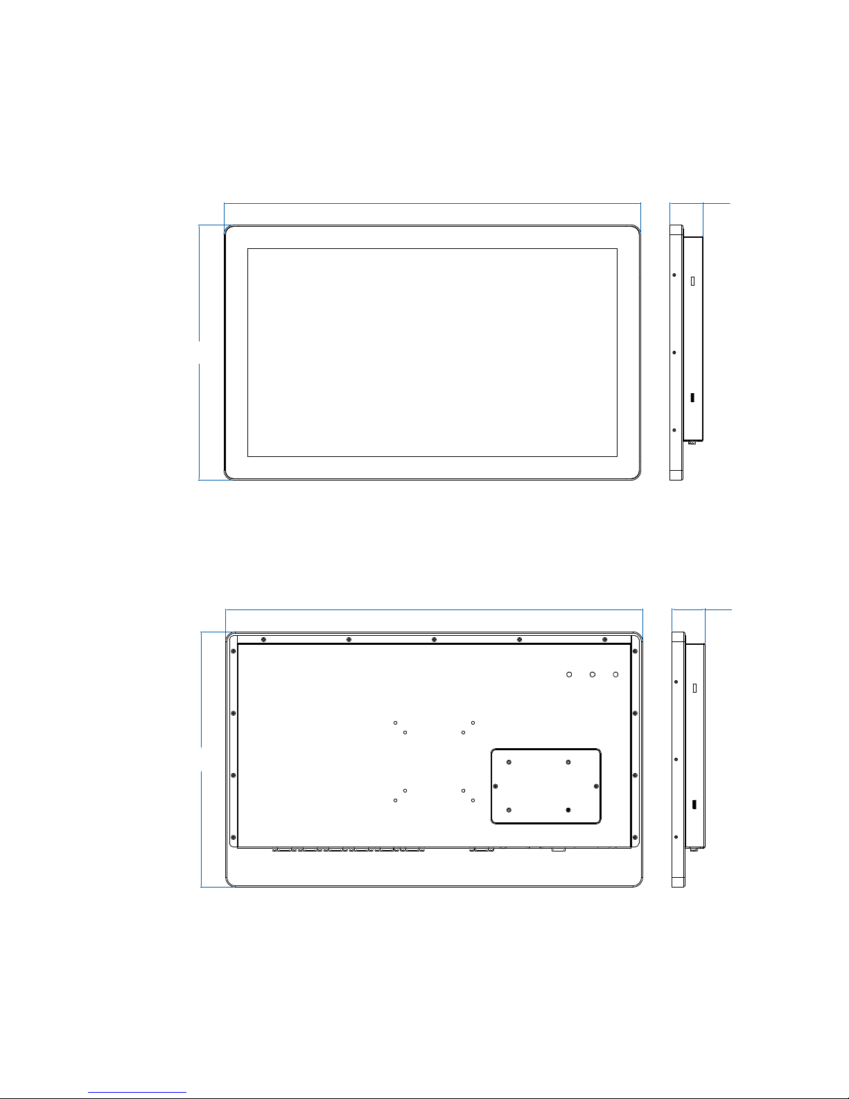
1.4 Mechanical Dimension
1.4.1 MCT-2021 Front View
537,60
(21,2)
42,60
(1,7)
329,0
(13.0)
Unit: mm (inch)
1.4.2 MTC-2021 Rear View
537,60
(21,2)
42,60
(1,7)
329,0
(13,0)
Unit: mm (inch)
Table of contents
Other Vecow Touch Panel manuals

Popular Touch Panel manuals by other brands


IBASE Technology
IBASE Technology ASTUT-152-RE1S user manual

YASKAWA
YASKAWA TP 610C manual

B&R
B&R Power Panel C Series user manual

Beijer Electronics
Beijer Electronics X2 control Hardware and installation manual

AXIOMTEK
AXIOMTEK GOT321W-521 user manual

TRIDONIC.ATCO
TRIDONIC.ATCO x-touchBOX Operation manual


