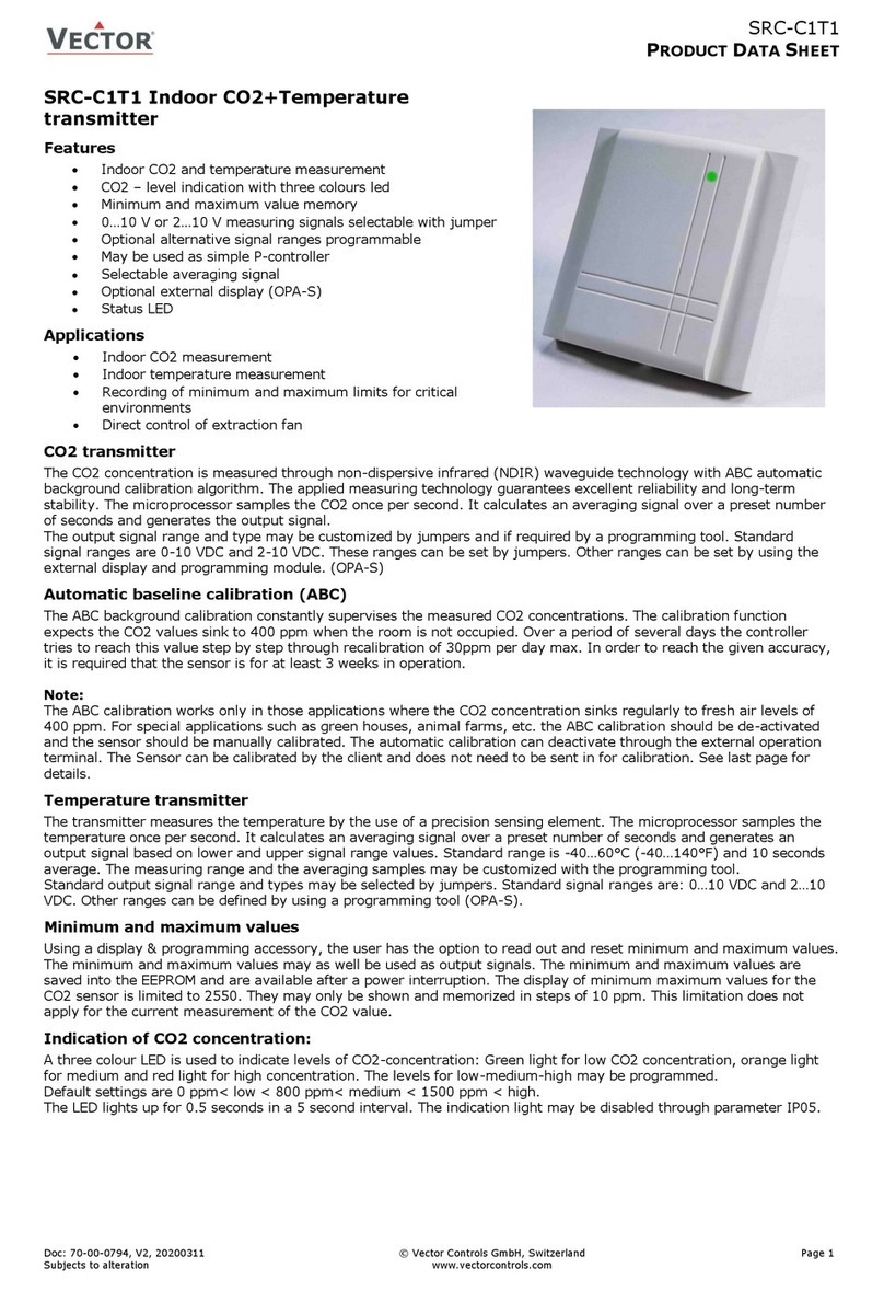
Vector SDC-C1 User manual

SDC-C1
DUCT CO2 TRANSMITTER
Doc: 70-00-0399A, V2.9, 20220405 © Vector Controls GmbH, Switzerland Page 1-8
Subject to change without notice www.vectorcontrols.com
SDC-C1 Duct CO2-transmitter
Features
•CO2 measurement for air ducts
•Minimum and maximum value memory
•0…10V, 0…20mA or 2…10V, 4…20mA measuring signals
selectable with jumpers
•Optional alternative signal ranges programmable
•May be used as simple P-controller
•Selectable averaging signal
•Optional internal or external display (OPC-S or OPA-S)
•Status LED
Applications
•Demand based ventilation for homes and offices based on
measurement of the CO2 concentration
•Preset standard measuring range 0...2000 ppm, max
possible range 0...5000 ppm
•Recording of minimum and maximum limits for critical environments
•Direct control of extraction fan
CO2 transmitter
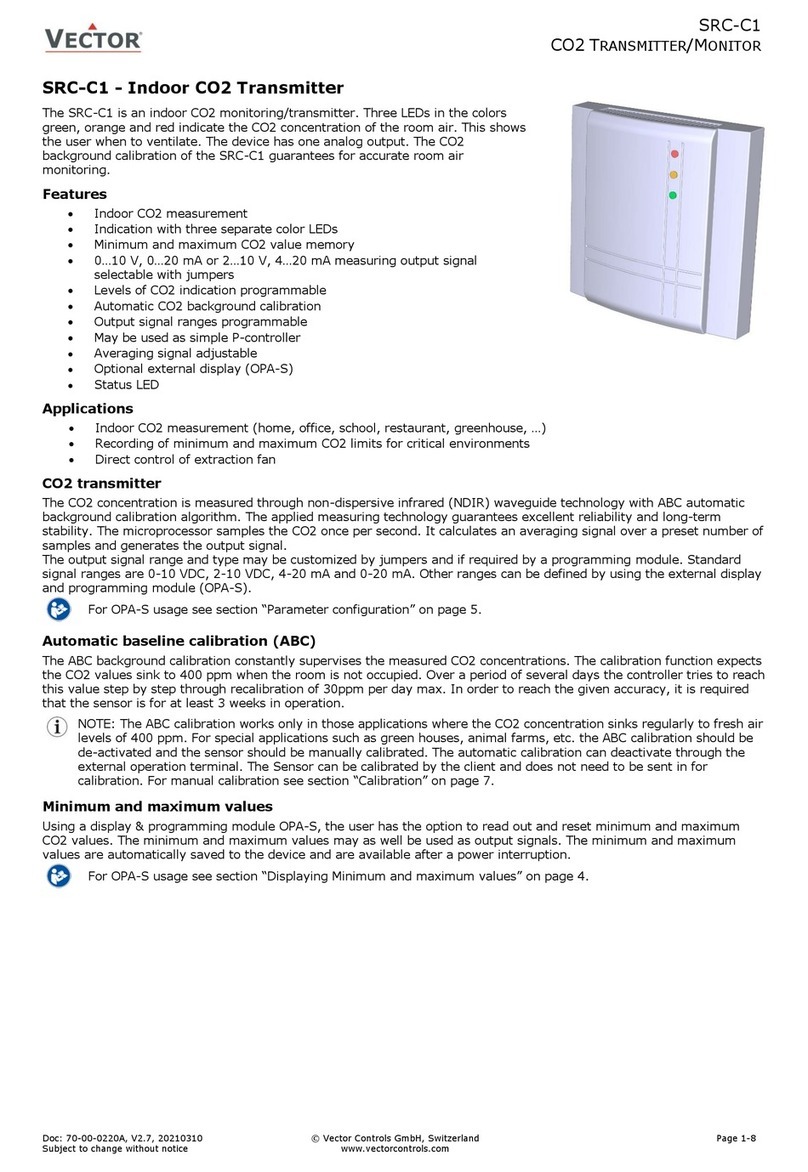
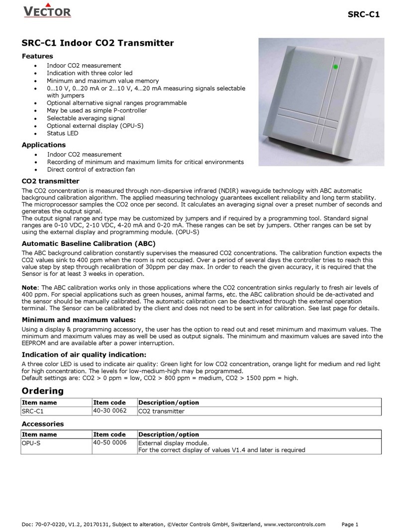
The CO2 concentration is measured through non-dispersive infrared (NDIR) waveguide technology with ABC automatic
background calibration algorithm. The applied measuring technology guarantees excellent reliability and long-term
stability. The microprocessor samples the CO2 once per second. It calculates an averaging signal over a preset number of
samples and generates the output signal.
The output signal range and type may be customized by jumpers and if required by a programming module. Standard
signal ranges are 0-10 VDC, 2-10 VDC, 4-20 mA and 0-20 mA. Other ranges can be defined by using the external display
and programming module (OPA-S).
For OPA-S, OPC-S usage see section “Parameter configuration” on page 5.
Automatic baseline calibration (ABC)
The ABC background calibration constantly supervises the measured CO2 concentrations. The calibration function expects
the CO2 values sink to 400 ppm when the room is not occupied. Over a period of several days the controller tries to reach
this value step by step through recalibration of 30ppm per day max. In order to reach the given accuracy, it is required
that the sensor is for at least 3 weeks in operation.
NOTE: The ABC calibration works only in those applications where the CO2 concentration sinks regularly to fresh air
levels of 400 ppm. For special applications such as green houses, animal farms, etc. the ABC calibration should be
de-activated and the sensor should be manually calibrated. The automatic calibration can deactivate through the
external operation terminal. See chapter parameter configuration for details. The Sensor can be calibrated by the
client and does not need to be sent in for calibration. For manual calibration see section “Calibration”on page 7.
Minimum and maximum values
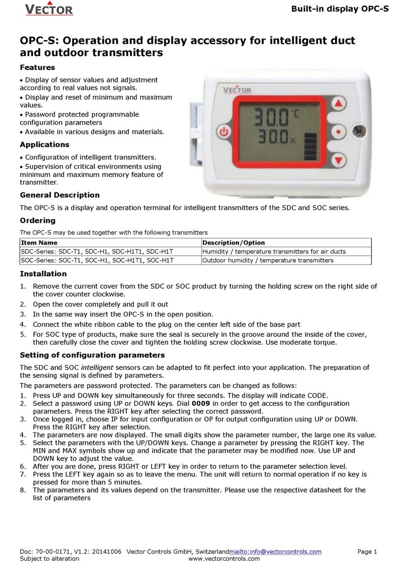
Using a display & programming module OPA-S or the optional built-in display and operation terminal OPC-S, the user has
the option to read out and reset minimum and maximum CO2 values. The minimum and maximum values may as well be
used as output signals. The minimum and maximum values are automatically saved to the device and are available after a
power interruption.
For OPA-S, OPC-S usage see section “Displaying minimum and maximum values” on page 4.
Safety
DANGER! Safety advice
This device is for use as a CO2 concentration indicator and CO2 transmitter for comfort applications. It is not a
safety device. Where a device failure could endanger human life and property, it is the responsibility of the client,
installer and system designer to add additional safety devices to prevent such a device failure. Ignoring
specifications and local regulations may cause equipment damage and endangers life and property. Tampering
with the device and misapplication will void warranty.
Types and Ordering
Product Name
Product Nr.
Description/Option
CO2 Sensor
SDC-C1-16-1
40-300152
CO2 transmitter for air ducts, 160 mm probe, incl. cable gland AMC-1
Accessories
OPC-S
40-500029
Built-in display and operation terminal.
OPA-S
40-500006
External display and operation terminal.
Note: For the correct display of values, V1.7 and later is required.
AMC-2
40-500074
Conduit connector: NPT thread

SDC-C1
DUCT CO2 TRANSMITTER
Doc: 70-00-0399A, V2.9, 20220405 © Vector Controls GmbH, Switzerland Page 2-8
Subject to change without notice www.vectorcontrols.com
Technical Specifications
Power supply
Operating voltage
24 VAC 50/60 Hz ± 10%, 24 VDC ± 10%
Power consumption
Max. 2 VA
Safety extra-low voltage (SELV)
HD 384, class II
Connection
Terminal connectors
For wire 0.34…2.5 mm2(AWG 24…12)
CO2 measurement
Sensing method
Non-dispersive infrared (NDIR) waveguide technology
with ABC automatic background calibration algorithm
Sampling method
Diffusion
Response time (90%)
2 Minutes
Measurement range
0 - 5000 ppm vol.
Repeatability
± 20 ppm ± 1 % of measured value
Accuracy
± 40 ppm ± 3 % of measured value
Pressure dependence
+ 1.6 % reading per kPa deviation from normal
pressure, 100 kPa
Signal outputs
Analog outputs
Output signal
Resolution
Maximum load
0…10 VDC, 0…20 mA or 2…10 VDC, 4…20 mA
10 bit, 9.7 mV, 0.019.5 mA
Voltage signal: ≥1kΩ, current signal: ≤250Ω
Environment
Operation
Climatic conditions
Temperature
Humidity
To IEC 721-3-3
class 3 K5
0…50 °C (32…122 °F)
<85% RH non-condensing
Transport & storage
Climatic conditions
Temperature
Humidity
Mechanical conditions
To IEC 721-3-2 and IEC 721-3-1
class 3 K3 and class 1 K3
-30…70 °C (-22…158 °F)
<95% RH non-condensing
class 2M2
Standards
Degree of protection
IP30 to EN 60 529
Safety class
III (IEC 60536)
Housing materials
Cover, back part
PC+ABS (UL94 class V-0)
General
Dimensions (H x W x D)
Transmitter case
Probe
68 x 91 x 47 mm (2.7 x 3.7 x 1.9 in)
Ø 14 x 160 mm, (Ø 0.55 x 6.2 in)
Weight (including package)
290 g (10.2 oz.)
Product testing and certification
Declaration of
Conformity
Information on the conformity of our products can be found on our website
www.vectorcontrols.com on the corresponding product page under "Downloads".

SDC-C1
DUCT CO2 TRANSMITTER
Doc: 70-00-0399A, V2.9, 20220405 © Vector Controls GmbH, Switzerland Page 3-8
Subject to change without notice www.vectorcontrols.com
Wiring and Connection
For jumper settings see section “Output signal configuration” on page 5.
Mounting instruction
See SDC-C1 installation sheet no. 70-000573 (www.vectorcontrols.com).
Dimension mm (inch)
2-10V/4-20mA
0-10V/0-20mA
Range
STATUS
LED
OPA-S
VDC
mA
AO1
JP4
JP1
OPC-S
Sensor
1 32
V+
GND
AO1
24V
CO2
0V
JP4 Signal range
VDC: 0…10V
mA: 0…20mA
VDC: 2…10V
mA: 4…20mA
JP1 Signal type
VDC
mA
1
V+
AC 24 V 50-60 Hz, DC +24 V ± 10%
2
GND
AC 0 V, DC 0 V
3
AO1
CO2, DC 0(2)...10 V, DC 0(4)...20 mA
91 (3.6)
68 (2.7)
14 x 157
47 (1.9)
(0.55 x 6.2)

SDC-C1
DUCT CO2 TRANSMITTER
Doc: 70-00-0399A, V2.9, 20220405 © Vector Controls GmbH, Switzerland Page 4-8
Subject to change without notice www.vectorcontrols.com
Operation
Displaying minimum and maximum values
To read out or reset the stored CO2 minimum and maximum values use the optional display & programming module
OPA-S or the built-in display & operation terminal OPC-S.
Use of OPA-S:
1. Open the SDC housing (see SDC-C1 installation sheet 70-000573 www.vectorcontrols.com).
2. Connect the OPA-S operating device to the OPA-S connector on the SDC (see section “Wiring and Connection” on
page 3). The measured CO2 value is displayed.
3. Press the “UP” key to see the maximum values or the “DOWN” key to see the minimum values.
4. To reset the minimum value, press the “DOWN” key for at least 5 seconds and wait until the value changes.
5. To reset the maximum value, press the “UP” key for at least 5 seconds and wait until the value changes.
Use of OPC-S:
1. Press the “UP” key to see the maximum values or the “DOWN” key to see the minimum values.
2. To reset the minimum value, press the “DOWN” key for at least 5 seconds and wait until the value changes.
3. To reset the maximum value, press the “UP” key for at least 5 seconds and wait until the value changes.
Status-LED
Error messages shown on OPA-S or OPC-S
Error
Description
Err 1:
Communication error: Verify cable connections, cable type and maximum distance.
Err 2:
CO2 sensor error: Make sure the sensor is not miss-calibrated. If possible, execute 400 ppm calibration. (see
section “Calibration” on page 7).
If error cannot be removed by calibrating the sensor, replace product.
2-10V/4-20mA
0-10V/0-20mA
Range
STATUS
LED
OPA-S
VDC
mA
AO1
JP4
JP1
OPC-S
Sensor
1 32
V+
GND
AO1
24V
CO2
0V
Status LED
- No light
: No power or unit damaged
- 5 sec flashing
: Normal
- 2 second blinking
: Calibration
- 10 second pulse
: Calibration successful
- Constant red > 10 sec
: Calibration or sensor error
Red Status-LED

SDC-C1
DUCT CO2 TRANSMITTER
Doc: 70-00-0399A, V2.9, 20220405 © Vector Controls GmbH, Switzerland Page 5-8
Subject to change without notice www.vectorcontrols.com
Configuration
Output signal configuration, Jumper settings
The analog output signal type for the AO1 output may be configured with jumper
JP1 for Voltage or Current control signals. The factory setting is Voltage.
For Jumper location see section “Wiring and Connection” on page 3.
The signal range may be set with jumper JP4for the analog signal output AO1.
JP4will only operate if the output range specified with output parameter OP 01
and OP 02 is left at the default value of 0…100%. With any other setting the
position of JP4has no influence and the signal range defined with the output
parameters OP 01 and OP 02 applies.
For Jumper location see section “Wiring and Connection” on page 3.
Parameter configuration
The transmitter can be adapted to fit perfectly into any application by adjusting the software parameters. The parameters
are set with the operation terminals OPA-S or the optional bult-in OPC-S. The OPA-S may also be used as remote
indicator.
NOTE: For the correct display of data, version 1.7 or grater of OPA-S is required.
OPA-S operation
1. Open SDC housing (see SDC-C1 installation sheet no. 70-00-0573 http://www.vectorcontrols.com/).
2. Connect the OPA-S operating device to the OPA-S connector on the SDC (see section “Wiring and Connection” on
page 3). The measured CO2 value is displayed.
3. Press the "Up" and "Down" keys simultaneously for more than 3 seconds. "Code 0000" is displayed.
4. Use the "UP" and "DOWN" keys to set the password "0009" and confirm with the "RIGHT" key.
5. Select "IP SEL (Input Parameter) or “OP SEL” (Output Parameter) with "UP" and "DOWN" and confirm with the
"RIGHT" key. The first parameter is displayed.
6. Use the "UP" and "DOWN" key to switch to the desired parameter. After pressing the "RIGHT" key adjust the
parameter value with the "UP" and "DOWN" keys. Confirm the setting with the "RIGHT" key.
7. Complete parameter setting by pressing the left "ON/OFF" key twice. The measured CO2 value is displayed.
Important
In order for the SDC-C1 to apply the new settings correctly, the parameter setting must be completed with the
left "ON/OFF" key!
Detailed information on the OPA-S can be found on the website www.vectorcontrols.com on the corresponding
product page under "Downloads".
OPC-S operation
1. Press the "Up" and "Down" keys simultaneously for more than 3 seconds. "Code 0000" is displayed.
2. Use the "UP" and "DOWN" keys to set the password "0009" and confirm with the "RIGHT" key.
3. Select "IP SEL (Input Parameter) or “OP SEL” (Output Parameter) with "UP" and "DOWN" and confirm with the
"RIGHT" key. The first parameter is displayed.
4. Use the "UP" and "DOWN" key to switch to the desired parameter. After pressing the "RIGHT" key adjust the
parameter value with the "UP" and "DOWN" keys. Confirm the setting with the "RIGHT" key.
5. Complete parameter setting by pressing the left "ON/OFF" key twice. The measured CO2 value is displayed.
Important
In order for the SDC-C1 to apply the new settings correctly, the parameter setting must be completed with the
left "ON/OFF" key!
Detailed information on the OPC-S can be found on the website www.vectorcontrols.com on the corresponding
product page under "Downloads".
Signal type
JP1
Voltage (VDC)
Current (mA)
Signal range
JP4
0…10 V, 0…20 mA
2…10 V, 4…20 mA

SDC-C1
DUCT CO2 TRANSMITTER
Doc: 70-00-0399A, V2.9, 20220405 © Vector Controls GmbH, Switzerland Page 6-8
Subject to change without notice www.vectorcontrols.com
Input configuration
Parameter
Description
Range
Default
IP 00
Not used
-
-
IP 01
CI1: Samples taken for averaging control signal 1)
1…255
10
IP 02
CI1: Calibration
-10…10%
0
IP 03
CI1: Minimum CO2 range ppm
(CO2 level when output is at its minimum)
0…5000 ppm
0 ppm
IP 04
CI1: Maximum CO2 range ppm
(CO2 level when output is at its maximum)
0…5000 ppm
2000 ppm
IP 05
CI1: Enable ABC automatic CO2 background calibration
ON, OFF
ON
IP 06
CI1: Calibrate CO2 sensor
Note: For normal operation, calibration is not required. Only experts
should calibrate the sensor.
0 = No calibration (default)
1 = Calibrate to gas (0 ppm)
2 = Calibrate to fresh air (400 ppm)
4 = Calibration error (status)
0…4
0
1) Sample interval: 1 sec.
Output configuration
Parameter
Description
Range
Default
OP 00
AO1 (CO2): Configuration of output signal:
0 = CO2 value
1 = Recorded minimum CO2 value
2 = Recorded maximum CO2 value
0…2
0
OP 01
AO1 (CO2): Minimum limitation of CO2 output signal 2) 3)
0…100 %
0 %
OP 02
AO1 (CO2): Maximum limitation of CO2 output signal 2) 3)
0…100 %
100 %
2) The Output signal will be scaled according to selected input range, selected limitation of output signal and the output
signal range selected by the jumper.
3) If the default values are changed, the position of JP2 has no influence and the output signal range defined with the
parameters applies.
IP
=
Input Parameter
OP
=
Output Parameter
CI
=
CO2 Input
AO
=
Analog Output
Examples of CO2 output signal on AO1:
Output signal type = Voltage (JP1 jumper setting)
Output signal range = 0…10 VDC (JP4 jumper setting)
Default setting
Custom setting
IP 03 = 0 ppm, IP 04 = 2000 ppm (range)
OP 00 = 0 (CO2 value)
OP 01 = 0 % (limitation)
OP 02 = 100 % (limitation)
OP 00 = 0 (CO2 value)
OP 01 = 20 % (limitation)
OP 02 = 80 % (limitation)
100%
10 V
0%
0 V 0 2000
ppm
Output
0 2000
ppm
Output
20%
2 V
80%
8 V

SDC-C1
DUCT CO2 TRANSMITTER
Doc: 70-00-0399A, V2.9, 20220405 © Vector Controls GmbH, Switzerland Page 7-8
Subject to change without notice www.vectorcontrols.com
Use the CO2-Transmitter as P-Controller
The CO2-transmitter may be converted into a proportional fresh air controller through a simple change of two parameter
settings:
1. Set a minimum CO2 concentration when the fresh air fan should start to run at its minimum speed for example
500 ppm. Set this as the minimum value in IP 03 parameter.
2. Then define the CO2 value when the fan should run at full speed, for example 1000 ppm and set this value in
IP 04.
Your transmitter has now been converted into an air quality P-Controller!
By using the analog output, the fan will start to run if the CO2 concentration is higher than 500 ppm. It increases to its
maximum when CO2 concentration reaches 1000 ppm.
Calibration
The CO2 sensor unit is maintenance free in normal environments thanks to the built-in self-correcting ABC algorithm
(Automatic Baseline Correction). This algorithm constantly keeps track of the sensor’s lowest reading over a 7 days
interval and slowly corrects for any long-term drift detected as compared to the expected fresh air value of 400 ppm CO2.
Rough handling and transportation might, however, result in a reduction of sensor reading accuracy. With time, the ABC
function will tune the readings back to the correct numbers. The default “tuning speed” is however limited to about 30
ppm/week. For post calibration convenience, in the event that one cannot wait for the ABC algorithm to cure any
calibration offset, manual calibration may be activated using following procedure. There are two calibration possibilities: 0
ppm and 400 ppm. Only one of the two manual calibration needs to be performed.
Calibration to 400 ppm (Fresh air)
1. Connect OPA-S or use the optional built-in OPC-S and expose the active sensor for at least 5 minutes to fresh
outside air. It is important to expose the sensor to only fresh air. An open window close to the sensor with a
higher level of CO2 could prevent a stable signal. Observe the CO2 value on the OPA-S.
2. Once the CO2 value has stabilized, login with the OPA-S and set IP 06 = 2, then exit configuration mode. The air
quality led will blink green color 2 times alternating with the status led in 2 second intervals.
3. The sensor will now wait for a stable concentration. Once the calibration has been executed, the status LED will
show constant RED and the green air quality led will blink for 10s if successful. If calibration is not successful (no
stability of concentration for 5 min, no communication with sensor) the red air quality led will blink instead and
the status LED will stay constantly on red in error mode. Recalibrate or restart device to stop error mode.
4. You may additionally verify the calibration using the OPA-S. If successful IP 06 will change to 0. If unsuccessful
the value of IP 06 changes to 4.
5. If unsuccessful, wait at least 1 minute before repeating the procedure again. Make sure that the sensor
environment is steady and calm!
Calibration to 0 ppm with CO2 free gas
1. Connect OPA-S or use the optional built-in OPC-S and place the sensor in a container filled with a gas mixture
which is free from CO2 (i.e., Nitrogen or Soda Lime CO2 scrubbed air). Observe the CO2 value on the OPA-S.
2. Once the CO2 value has stabilized, login with the OPA-S and set IP 06 = 1, then exit configuration mode. The air
quality LED will blink in red color 2 times alternating with the status led in 2 second intervals.
3. The sensor will now wait for a stable concentration. Once the calibration has been executed, the status LED will
show constant RED and the green air quality led will blink for 10s if successful. If calibration is not successful (no
stability of concentration for 5 min, no communication with sensor) the red air quality led will blink instead and
the status LED will stay constantly on red in error mode. Recalibrate or restart device to stop error mode.
4. You may additionally verify the calibration using the OPA-S. If successful IP 06 will change to 0. If unsuccessful
the value of IP 06 changes to 4.
5. If unsuccessful, wait at least 1 minute before repeating the procedure again. Make sure that the sensor
environment is steady and calm!
This manual suits for next models
2
Table of contents
Other Vector Transmitter manuals
Popular Transmitter manuals by other brands

NIVELCO
NIVELCO EasyTREK SCD-300 Series Installation and programming manual

Comtek
Comtek M-216 Operator's manual

IMI SENSORS
IMI SENSORS HT640B01 Installation and operating manual

E+E Elektronik
E+E Elektronik EE22 Series manual

Honeywell
Honeywell XNX Technical manual

ALFAtron
ALFAtron tpuhd-70-rs user manual