4
VEEDER-ROOT
82345
P
OP1
OP2
PGM RST
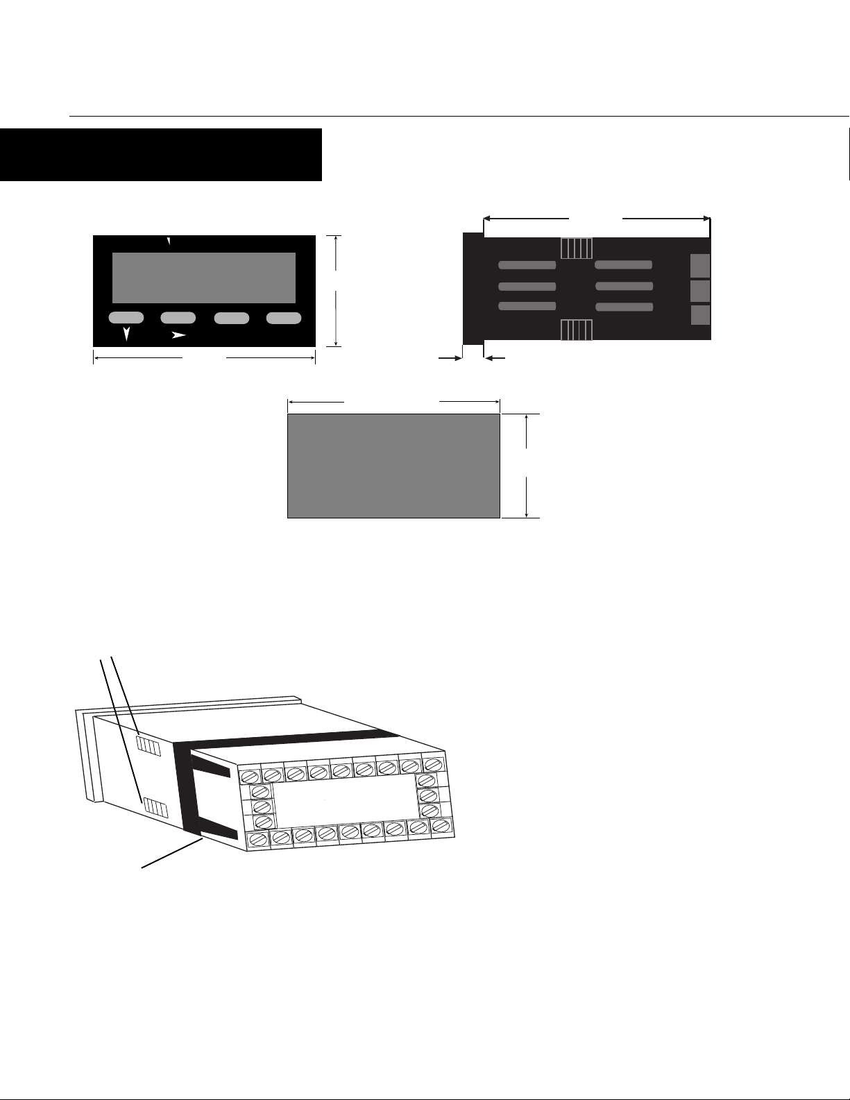
OPERATION
FRONT PANEL
Down Key Scroll Key Program Key Reset Key
Secondary Display
Scroll
Down InOperationMode: Usedineditoperationto decrement
thedigithighlightedbytheScrollkey.
InProgramMode: UsedinEditOperation to decrement
the digit highlightedby the Scrollkey, if thesettingis
anumerical value, or present the next in the series of
choicesforthatparameter.
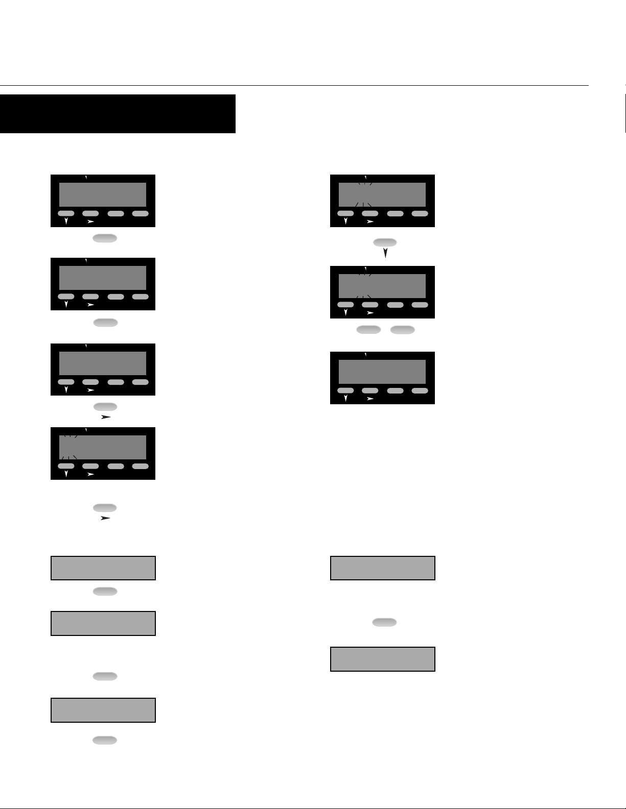
Program InOperationMode: Used tomove between the
parametersandtoenteraneditedpresetvalue.
Holding the key down for 3 seconds will cause the
unittoenterProgramMode.
InProgram Mode: Used to move from one parameter to
thenextandentertheeditedparametervalues.
Holding the key down for 3 seconds will cause the
unittoreturntoOperationMode.
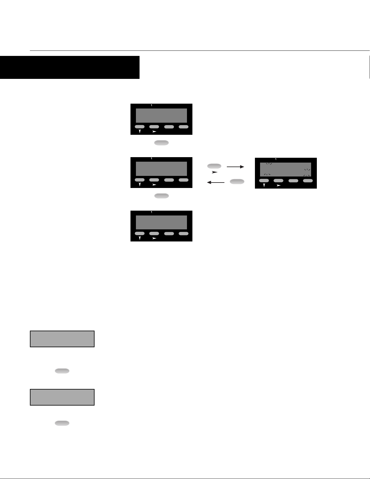
InAllmodes: Movesthe unitinto Edit Operation,
whichisindicatedbytheleftmostdigitflashing.
Successive presses of the key are used to move to the
digit to be edited. Wrap around will occur from least
significantdigittomostsignificantdigit.
Reset InOperationMode: Resetsthecountvalue,batch
value,or background totalto zero (or to the preset in
countdownoperation). Parametermustbedisplayed
to be reset. This button can be disabled via the "Front
PanelResetEnable"parameterinProgramMode.
InProgramMode: Nofunction.
InAllmodes: Willabortan Edit Operation and return
thepreset/parametertoitspreviousvalue.
Down &
Scroll
together
Key Primary InOperationMode: Defaultdisplayisthecountvalue.
Canbescrolledusing the programkey to displaythe
otherparameters. Ifthe"Help"functionisenabled,
thisdisplaywillfirstshowtheparameterdescription
for3 seconds(see page5 for example).
InProgramMode: Displaysthevalueorselectionfor
thecurrent parameter. If the "Help" function is
enabled,thisdisplaywillfirstshowtheparameter
descriptionfor3seconds(seepage6forexample).
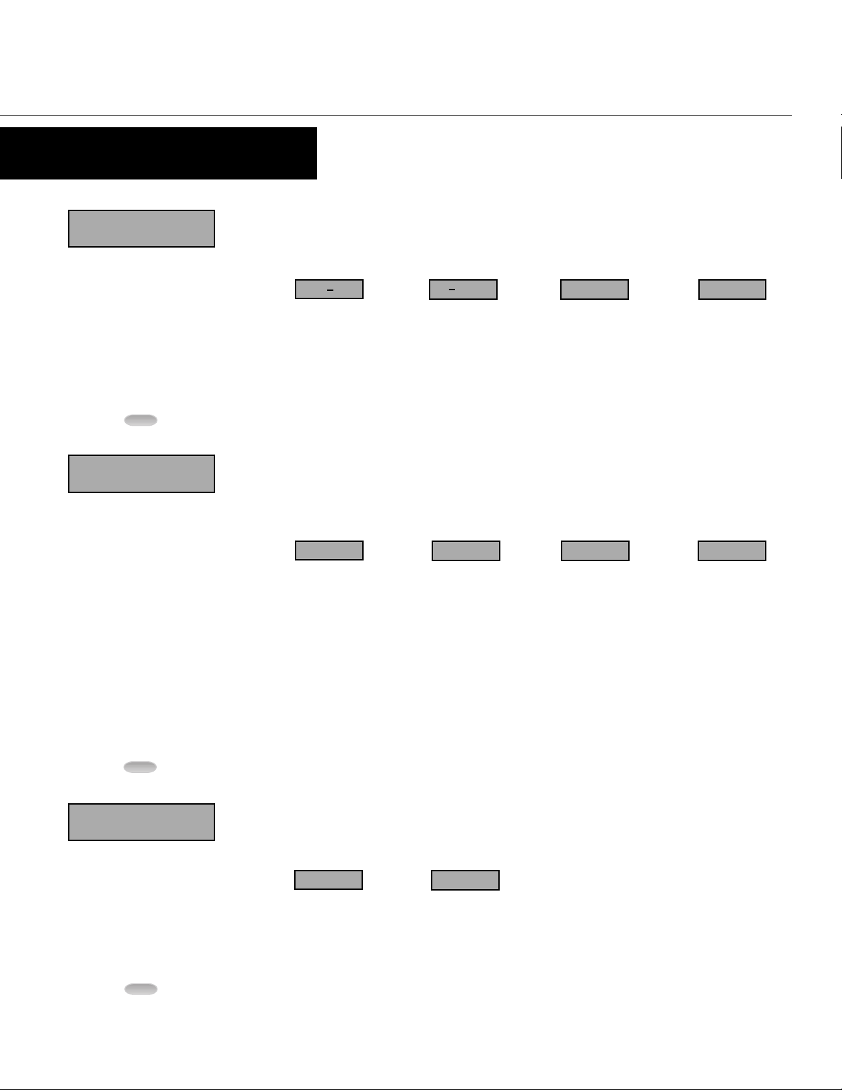
Secondary InOperationMode: Indicatesalphabeticallywhether
Preset,BatchValue,BatchPreset,orBackgroundTotal
isbeing viewed on the primary display. This displayis
blankwhen CountValueisbeingshown.
InProgramMode: Providesa 1 digit alpha ornumeric
charactertoindicatewhichparametervalueisbeing
shownontheprimarydisplay.
Output
Indicators InOperationMode: OP1illuminateswhenOutput1 is
active. OP2illuminateswhenOutput2is active.
InProgramMode: Nofunction.
Display Functions
Key Functions
Function Display Function
Output Indicators
Primary Display