Kobold DF ZL Series User manual

Operating Instructions
for
Counter Electronic
Model: ZED-Z
or DF-…ZLxxx
or Model-…ExxR

ZED-Z
page 2 ZED-Z K11/0522
1. Contents
1. Contents........................................................................................................2
2. Note ..............................................................................................................3
3. Instrument Inspection....................................................................................3
4. Regulation Use .............................................................................................3
5. Operating Principle........................................................................................4
6. Electrical Connection ....................................................................................5
6.1 ZED-Z, DRB-…ExxR, DPE-…ExxR field housing and control panel
installation............................................................................................5
6.2 DF-…ZLxxx, Model-…ExxR cable connection.................................5
6.3 Model-…ExxR cable connection + plug connection.........................6
6.4 Connection example............................................................................6
7. Operation / Configuration / Adjustments .......................................................7
7.1 General................................................................................................7
7.2 Function of the control keys.................................................................8
7.3 Character explanation for main menu..................................................9
7.4 General Settings................................................................................10
7.5 Flow, analogue output and relay 1.....................................................12
7.6 Relay 2 and volume counter..............................................................15
7.7 User alignment and Service-Settings.................................................17
7.8 Error report ........................................................................................20
8. Relay Functions ..........................................................................................21
8.1 Switching characteristic limit value ....................................................21
8.2 Switching characteristic window ........................................................21
9. Technical Information..................................................................................22
10. Order Codes ...............................................................................................23
11. Dimensions .................................................................................................23
12. EU Declaration of Conformance .................................................................24
Manufactured and sold by:
Kobold Messring GmbH
Nordring 22-24
D-65719 Hofheim
Tel.: +49(0)6192-2990
Fax: +49(0)6192-23398
E-Mail: [email protected]
Internet: www.kobold.com

ZED-Z
ZED-Z K11/0522 page 3
2. Note
Please read these operating instructions before unpacking and putting the unit
into operation. Follow the instructions precisely as described herein.
The instruction manuals on our website www.kobold.com are always for
currently manufactured version of our products. Due to technical changes, the
instruction manuals available online may not always correspond to the product
version you have purchased. If you need an instruction manual that corresponds
to the purchased product version, you can request it from us free of charge by
email (info.de@kobold.com) in PDF format, specifying the relevant invoice
number and serial number. If you wish, the operating instructions can also be
sent to you by post in paper form against an applicable postage fee.
The devices are only to be used, maintained and serviced by persons familiar
with these operating instructions and in accordance with local regulations
applying to Health & Safety and prevention of accidents.
When used in machines, the measuring unit should be used only when the
machines fulfil the EC-machine guidelines.
3. Instrument Inspection
Instruments are inspected before shipping and sent out in perfect condition.
Should damage to a device be visible, we recommend a thorough inspection of
the delivery packaging. In case of damage, please inform your parcel service /
forwarding agent immediately, since they are responsible for damages during
transit.
Scope of delivery:
The standard delivery includes:
•Counter Electronic model: ZED-Z or flowmeter incl. Counter Electronic
4. Regulation Use
Any use of the Counter Electronic, model: ZED-Z, which exceeds the
manufacturer’s specification, may invalidate its warranty. Therefore, any
resulting damage is not the responsibility of the manufacturer. The user
assumes all risk for such usage.

ZED-Z
page 4 ZED-Z K11/0522
5. Operating Principle
The evaluation unit changes the frequency signal of the pickup into a 3(4)-digit
flow reading with selectable measurement unit (top display line), and into a
scalable analogue signal. The flow quantity is added up in a part quantity meter
and a total quantity meter and then displayed in the bottom line of the screen.
The quantity meter’s units of measurement are selectable.
The two relays with floating output changeover contacts continuously monitor if
the freely adjustable limits are exceeded or fallen short of. Here, it is possible to
choose between threshold value and window monitoring.
Switching point, hysteresis, a window point, and switch on or off delay can be
set separately for each relay. The switching points can also be set directly by
using the control keys without having to change over into the menu.
Alternatively, it is also possible to monitor the quantity meter to see if it is
exceeded. A red LED indicates with the switching status.
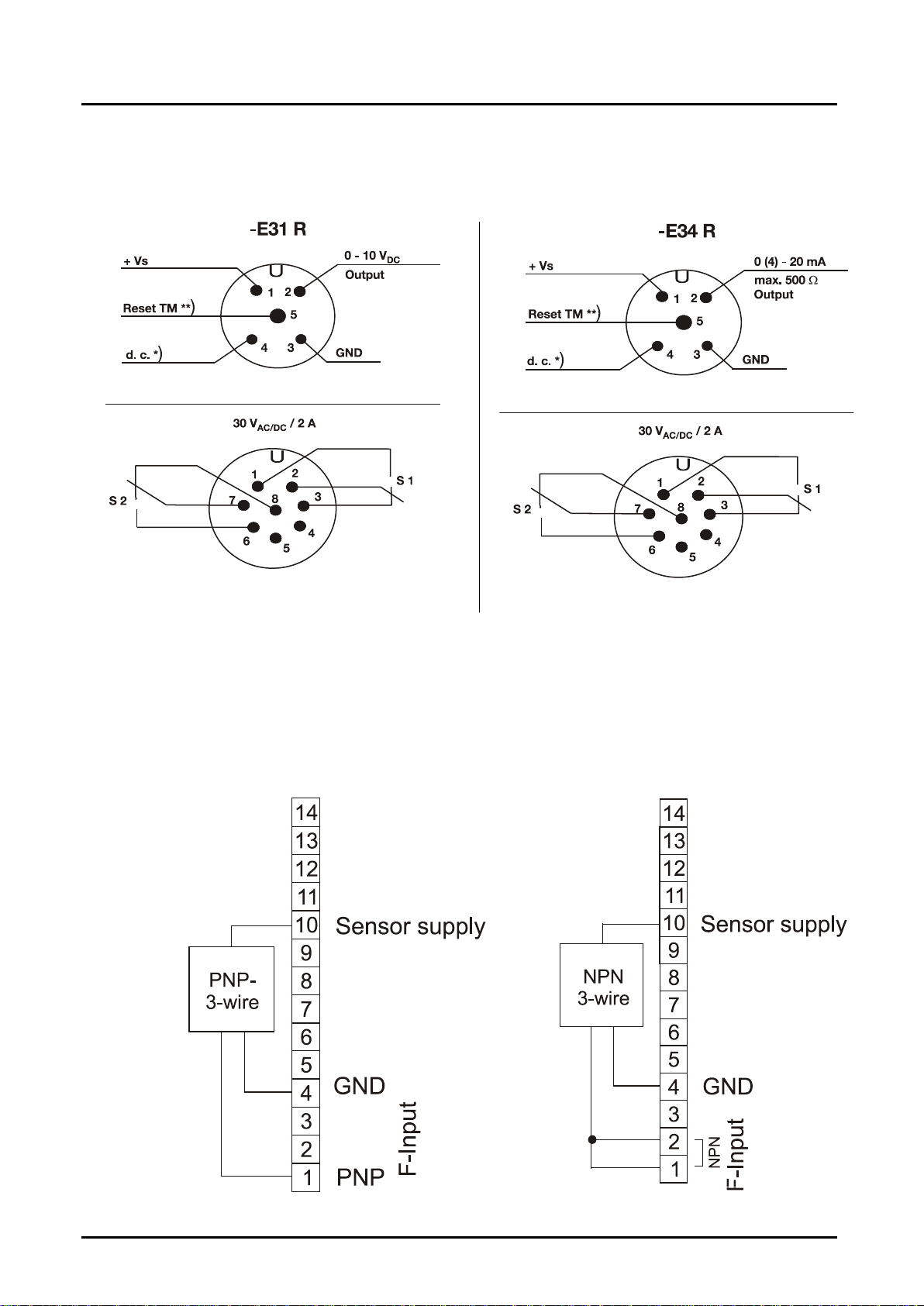
The analogue output is optionally available as current output with 0(4)...20 mA
or as voltage output with 0...10 V. The Parameter names can be shown in the
menu in German or English. If used where the flow readings change rapidly, the
display can be pacified and the analogue reading averaged by switching on
some software. When using analogue output 0 – 10 V the customer must put a
jumper between the terminals 7 and 8.
A MIN/MAX reading memory determines the extreme readings of the flow. The
display of the readings and the resetting are achieved by using the keys without
having to change into the menu. Resetting by using the keys can also be
blocked. If the maximum set flow (exceeded range) is exceeded, it will be shown
on the display.
The set parameters can be protected against unauthorized alteration by using a
password function.
Range of functions
Quantity meter and flow meter with digital display, switch and analogue output:
•Measurement and display total, part and flow quantities
•Free scaling using input of frequency and measured value
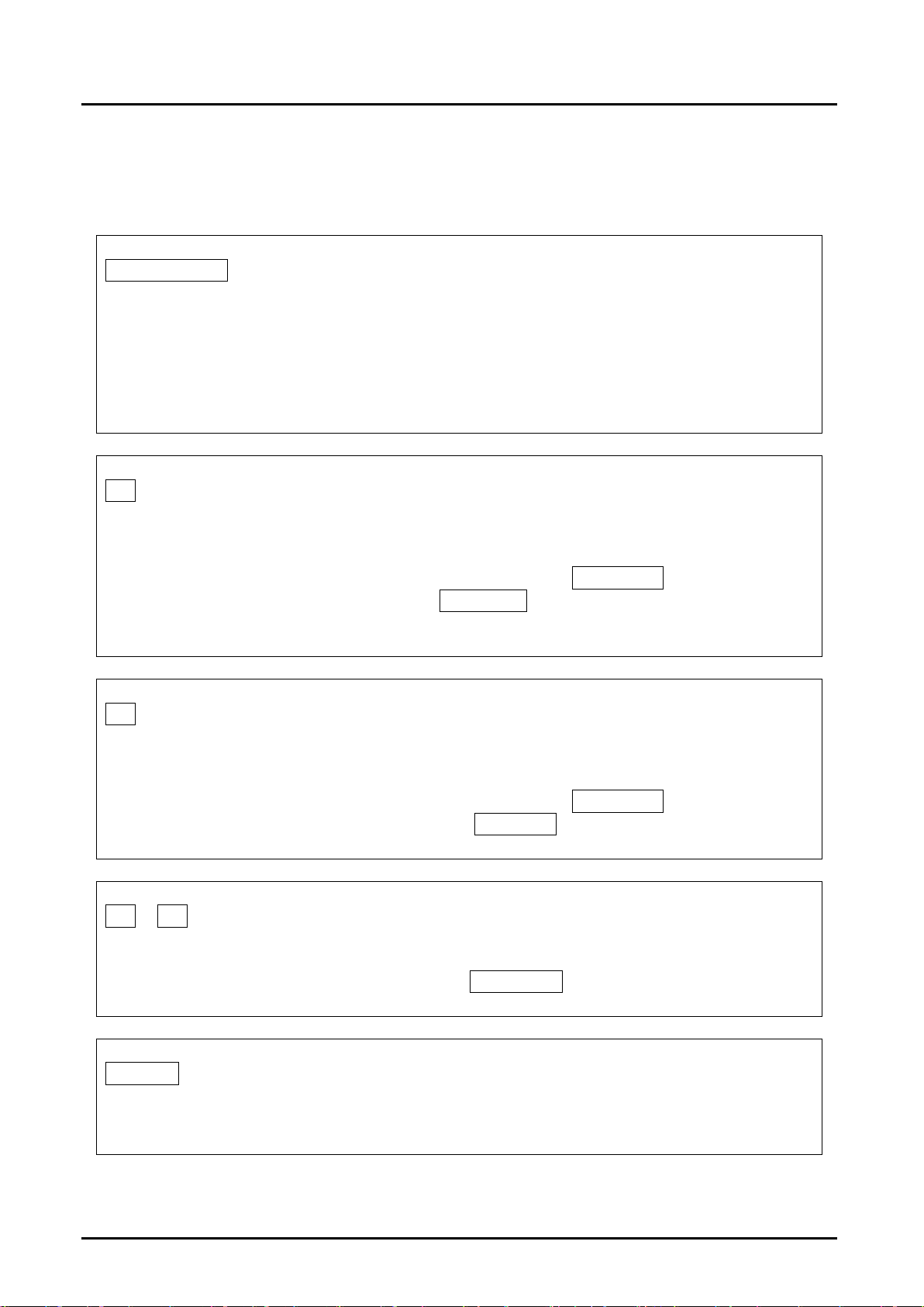
•Control input for part quantity reset
•2 switching outputs, freely programmable as flow monitor or for monitoring
the part and total quantity
•Analogue output 0(4)-20 mA oder 0-10 V
•MIN/MAX memory

ZED-Z
ZED-Z K11/0522 page 5
6. Electrical Connection
6.1 ZED-Z, DRB-…ExxR, DPE-…ExxR
field housing and control panel installation
*) Don’t connect terminal!
**) Reset TM – GND => reset part quantity counter
6.2 DF-…ZLxxx, Model-…ExxR
cable connection
Wire number ZED-Counter electronics
1
+24 V
DC
2
GND
3
4-20 mA / 0-10 V
4
GND
5
d.c. *)
6
Reset TM
7
Relay S1 N/O
8
Relay S1 COM
9
Relay S2 N/O
10
Relay S2 COM
*) Don’t connect terminal!
**) Reset TM – GND => reset part quantity counter
**)

ZED-Z
page 6 ZED-Z K11/0522
6.3 Model-…ExxR
cable connection + plug connection
*) Don’t connect contact !
**) Reset TM – GND => reset part quantity counter
6.4 Connection example
PNP-Sensor NPN-Sensor

ZED-Z
ZED-Z K11/0522 page 7
7
8
9
GND
0-10 V V
Analogausgang 0-10 V
7
8
9
10
GND
0-20 mA
Analogausgang 0-20 mA
NAMUR-Sensor
7. Operation / Configuration /
Adjustments
7.1 General
Only the menu items which lines are marked in the selection matrix in grey
colour, are available in the respective instrument version.
Italic written values are blinking in the display, if they have been chosen
for any input.
The parameter can only be changed, if the security code has been
entered correctly! The message „locked“ will appear if the input has
not been activated.
analogue output 0-10 V
analogue output 0-20 mA

ZED-Z
page 8 ZED-Z K11/0522
7.2 Function of the control keys
Operating mode >Measure< :
PGM/ENTER
- Press briefly: a) Display total quantity, then
Display corresponding scale unit or
b) Reset status reports.
- Press for 3 sec: Switch to operating mode >Parameterize<.
▼
- - Press briefly: Display min. flow value.
- Press for 3 sec: Enter switching point for Relay S1 s1SPoint
(only if parameter SPdirect is set to “yes”).
.
▲
- - Press briefly: Display max. flow value.
- Press for 3 sec: Enter switching point for Relay S2 s2SPoint
(only when parameter SPdirect is switched to “yes”).
▼+ ▲
Press for 3 sec: Sets min. and max. value memory to flow value
(only when parameter fMMReDir is switched to “yes”).
RESET
- Press for 3 sec: Sets the part quantity counter to 0.

ZED-Z
ZED-Z K11/0522 page 9
Operating mode >Parameterize<:
PGM/ENTER
- Press briefly: a) Open parameter group or
b) Change parameter (go lower in menu level) or
c) Adopt value input.
- Press for 3 sec: Abort input (ESC) and go back one
menu level.
▼
- Press briefly: a) Select parameter group or parameter or
b) Reduce selected number by 1 or
c) Select list value (e.g.... L/m, L/h, m3/m, ...).
▲
- Press briefly: a) Select parameter group or parameter or
b) Increase selected number by 1 or
c) Select list value (e.g.... m3/m, L/h, L/m, ...).
RESET
- No function in this mode.
Note: If no button is pressed for 20 seconds during parameterising, the
instrument automatically switches back into >measuring< mode.
7.3 Character explanation for main menu
( e) -Button PGM/ENTER press shortly.
( E) -Button PGM/ENTER press and hold for approx. 3 seconds.
(▼) -Button ▼press shortly.
(▲) -Button ▲press shortly.

ZED-Z
page 10 ZED-Z K11/0522
7.4 General Settings

ZED-Z
ZED-Z K11/0522 page 11
GENERAL SETTINGS
Menu Item Parameter / Function Explanation / Values / Other
Language Select menu language
German or English
fUnitFS * Measuring unit for flow
measurement
mL/s, mL/m, L/s, L/m, L/h, m3/m, m3/h,
GPM, GPH, UU/s, UU/m, UU/h
fValueFS * Maximum measuring range value
for flow measurement
Range = 0,00...99,9..._100...9999
fMinVal * Minimum measuring range value
for flow measurement
Basis is fValueFS and fUnitFS
If the level drops below this, the flow indicator goes to 0.
fPls/rev* Impulse per sensor wheel
revolution
Number of impulses per revolution of the sensor wheel or the like
Necessary for long-term period averaging if the readings per revolution vary.
The function is switched off when the input value is 1.
fJumpVD* Flow switch value for attenuation
cut-off
Value in %, basis is fValueFS and fUnitFS.
Attenuation does not function if the switch value is 0%.
fOverflV * Flow overflow value (overflow)
Value in %, basis is fValueFS and fUnitFS.
If exceeded, an M100 report is generated and faded in, alternating
with the flow indicator.
The report is saved and can be reset by briefly pressing the
PGM key.
fFactor Select pulse ration
Selection of works calibration or user calibration.
(only for devices Model DF-...ZLxxx and Model-...ExxR)
UserUnit. Special volume unit
Customer-specific special unit UU.
The value entered corresponds to the number of litres of the special unit, e.g.
in the case of the unit Barrel the factor would for example be 115.6271.
SPdirect Activation of direct input switching
point
yes: Direct input of switching points s1SPoint and
s2SPoint is possible using the keys (default).
no: The switching points can only be set in the menu .
*) Only for ZED devices: Device-specific parameter, is only visible after activation in the SecCode menu item in the SERVICE
menu group, and can be changed.

ZED-Z
page 12 ZED-Z K11/0522
7.5 Flow, analogue output and relay 1

ZED-Z
ZED-Z K11/0522 page 13
FLOW
Menu Item
Parameter / Function
Explanation / Values / Other
fUnit Unit of flow indicator
mL/s, mL/m, L/s, L/m, L/h, m3/m, m3/h,
GPM, GPH, UU/s, UU/m, UU/h
fDamping Attenuation of reading fluctuations in the flow indicator
The attenuation pacifies the flow indicator.
The attenuation value is the approximate equivalent of the setting time
of the display value to c. 90% of a measured value jump in seconds.
(Parameter is blocked at DF-...ZLxxx devices).
fMMReDir
Resets the Min/Max flow value directly using the keys,
without using the menu
yes: direct resetting of the Min/Max value memory by simultaneously
pressing (3 sec) the (+) and (-) keys (default).
no: memory reset only possible with fMMRST.
fMMRST Resets the Min/Max flow value memory of the flow
indicator
yes: Resets Min / Max value memory for the flow
no: No action.
ANALOGUE OUTPUT
Menu Item
Parameter / Function
Explanation / Values / Other
aLIFE 0 Select Life Zero
Offset at power output: 0 mA or 4 mA
at 0-10 V ≙0 mA →0 V and 4 mA → 2 V
aLowFlow
Flow reading at 0/4 mA or 0/2 V
Lower flow reading of gauged output range,
value has the same unit as the flow indicator
aHighFlo Flow reading at 20 mA or 10 V
Upper flow reading of gauged output range,
value has the same unit as the flow indicator

ZED-Z
page 14 ZED-Z K11/0522
RELAY S1
Menu Item
Parameter / Function
Explanation / Values / Other
s1Funct. Relay1 Function selection
Flow.: Monitoring of an adjustable flow value (s1SPoint).
TA Limit: Monitoring of an adjustable total volume (s1TA-Lim).
PA-Limit: Monitoring of an adjustable part volume (s1PA-Lim).
see 8.0 Relay functions
s1Char. Relay1 Switch characteristic
Limit: Monitoring a reading (s1SPoint).
Window: Monitoring an adjustable measuring range
(s1SPoint...s1Fpunkt).
(only if s1Funct. is set to Flow)
s1Logic Relay1 Switch logic
normal: Relay 1 activated when the limit value is exceeded.
invers: Relay 1 drops out when the limit value is exceeded.
s1SPoint Relay1 Switchpoint
Reading is in the same units as the flow indicator.
(only if s1Funct. is set to Flow)
s1Hyste Relay1 Hysteresis
Reading is in the same units as the flow indicator.
(only if s1Funct. is set to Flow)
s1FPoint Relay1 Windowpoint
Reading is in the same units as the flow indicator.
(only if s1Funct. is set to Flow und s1Char. auf Window )
s1SDelay Relay1 Switch delay
Delays the switching of the relay when the limit value is exceeded.
Range:_ 0,0...99,9 sec
(only if s1Funct. is set to Flow)
s1RDelay Relay1 Reset delay
Delays the switching of the relay when the limit value is undershot.
Range:_ 0,0...99,9 sec
(only if s1Funct. is set to Flow)
s1PA-Lim Relay1 Part volume limit value
Limit value for monitoring the part volume counter.
Reading is in the same units as the part volume unit (PA-Unit.) in
counter menu group.
(only if s1Funct. Is set to GM Limit )
s1TA-Lim Relay1 Total volume limit value
Limit value for monitoring the total volume counter.
Reading is in the same units as the total volume unit (TA-Unit) in
counter menu group.
(only if s1Funct. Is set to TA Limit )

ZED-Z
ZED-Z K11/0522 page 15
7.6 Relay 2 and volume counter

ZED-Z
page 16 ZED-Z K11/0522
RELAY S2
Menu Item
Parameter / Function
Explanation / Values / Other
s2Funct. Relay2 Function selection
Flow : Monitoring of an adjustable flow value (s2SPoint).
TA-Limit: Monitoring of an adjustable total volume (s2TA-Lim).
PA-Limit: Monitoring of an adjustable part volume (s2PA-Lim).
see 8.0 Relay functions
s2Char. Relay2 Switch characteristic
Limit: Monitoring a reading (s2SPoint).
Window: Monitoring an adjustable measuring range
(s2SPoint...s12punkt).
(only if s2Funct. is set to Flow)
s2Logic Relay2 Switch logic
normal: Relay 2 activated when the limit value is exceeded.
invers: Relay 2 drops out when the limit value is exceeded.
s2SPoint Relay2 Switchpoint
Reading is in the same units as the flow indicator.
(only if s2Funct. is set to Flow)
s2Hyste Relay2 Hysteresis
Reading is in the same units as the flow indicator.
(only if s2Funct. is set to Flow)
s2FPoint Relay2 Windowpoint
Reading is in the same units as the flow indicator.
(only if s2Funct. is set to Flow)and s2Char. Is set to Window )
s2SDelay Relay2 Switch delay
Delays the switching of the relay when the limit value is exceeded.
Range:_ 0,0...99,9 sec
(only if s2Funct. is set to Flow)
s2RDelay Relay2 Reset delay
Delays the switching of the relay when the limit value is undershot.
Range:_ 0,0...99,9 sec
(only if s2Funct. is set to Flow)
s2PA-Lim Relay2 Part volume limit value
Limit for monitoring the part volume counter.
Reading is in the same units as the part volume units (PA-Unit.)
in the counter menu group.
(only if s2Funct. Is set to PA-Limit )
s2TA-Lim Relay2 Total volume limit value
Limit for monitoring the total volume counter.
Reading is in the same units as the total volume units
(TA-Unit) in the counter menu group.
(only if s2Funct. Is set to TA-Limit )

ZED-Z
ZED-Z K11/0522 page 17
VOLUME COUNTER
Menu Item
Parameter / Function
Explanation / Values / Other
PA-Unit. Units on the part volume indicator
mL, L, m3, gal, mgal, UU
PA =0? Set part volume counter to 0
yes: Part volume counter is set to 0
no: No action
PA0dirct 0-setting option of the part
volume counter released using
the reset key
yes: Released (default)
no: Blocked
TA-Unit Measuring units on the total
volume indicator
mL, L, m3, gal, mgal, UU
TA =0? Set total volume counter to 0
yes: Total volume counter is set to 0
no: No action
7.7 User alignment and Service-Settings

ZED-Z
page 18 ZED-Z K11/0522
USER CALIBRATION
Menu Item
Function / Description
CAL Freq*
Calibrate by entering frequency and flow.
In the menu item CAL Freq the bottom line always shows the current pulse value of the
User calibration.
Calibration process:
a) FlowVal Enter nominal flow value of the sensor. > (e) press >
b) FlowUnit Enter unit for flow value. > (e) press >
c) Freq.Val. Enter nominal frequency > finish with (e).
The new pulse value of the User calibration is calculated from these three values and saved
as user calibration for the flow measurement, e.g. 20.2757 pls./litre.
CAL Vol.
Calibration process using impulse counting and volume input (cc procedure).
In the menu item CAL Vol. the bottom line always shows the current pulse value of the
User calibration.
Calibration process:
a) PulseCnt measures number of impulses
(e) press > start counter (impulses are counted) > (e) press > stops counter.
b) Vol.Val Enter measured volume value > (e) press.
c) Vol.Unit Enter unit for volume value > finish with (e).
The pulse value of the User calibration is calculated from these three values and is saved
as the user calibration for the flow measurement, e.g. 3900,5 pls./L.
*) CAL Freq – Only possible with ZED devices.
Note: With ZED devices it is necessary to enable the device-specific
parameter input in the menu Item SecCode in the menu SERVICE in order
to activate the USER-ABGLEICH function.
Note: If the new pulse ratio will be used for measurement, than the menu
item fFaktor in the menu group General Settings must be setted to USER
calibration.

ZED-Z
ZED-Z K11/0522 page 19
SERVICE
Menu Item
Function
Explanation / Values / Other
SecCode
Input
Enter security code
Input of 4-digit security code
and enablement of the parameter change.
The following passwords have been defined:
3461 – General menu release
6571 – Activates the device-specific
parameters (only ZED und Model-
devices)
SecCode
change
Change security code
Define or change security code for the first time
or change.
If no code ( = 0000) has been set, then the
parameter values set are unsecured!
Save Prm
Save parameter record
Save current settings
Load Prm
Load parameter record
Restore saved settings (reload).
Restore
Default
Reset to works default settings
Load initial setting with password 2541.
The function is blocked when the sensor has
been factory-calibrated (only Model-devices).

ZED-Z
page 20 ZED-Z K11/0522
7.8 Error report
Error code
Reason
Reset
E102
UU User unit may not be ≤0
Correct parameter
E142
Distance between upper and lower analogue
value too small (based on the actual flow)
Correct parameter
E143
Distance between upper and lower analogue
value too small (based on the dosing amount)
Correct parameter
E 161
Value is greater than maximum measuring
range value.
Correct parameter
E162
Hysteresis too large
Correct parameter
E 163
Window point is lower than switching point.
Correct parameter
E242
Frequency must be between 0,2 and 2000 Hz
Correct parameter
E245
Calculated pulse value out of valid range
Correct parameter
E300
Error memory value of totalising/part counter
Keep ▲+ ▼pressed about
20 seconds
M100
Overflow
Acknowledge with PGM button
####
Value does not fit in the display
Choose suitable measuring unit
This manual suits for next models
2
Table of contents
Other Kobold Cash Counter manuals
Popular Cash Counter manuals by other brands

Agilent Technologies
Agilent Technologies 53210A Options installation

Selecta
Selecta CC-1431 instruction manual

Line Seiki
Line Seiki G48-305N instruction manual

Eaton
Eaton Durant AMBASSADOR Series Installation and operation manual

VDO
VDO VIEWLINE HOURS COUNTER Product information

Ditel
Ditel Kosmos series manual