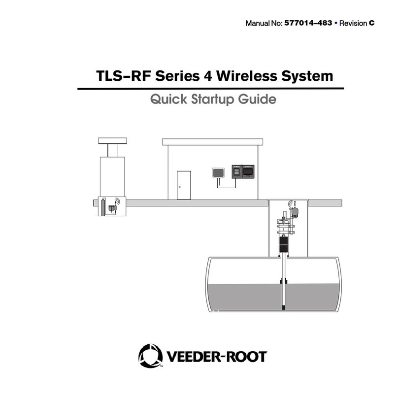
Veeder-Root TLS-RF Series User manual

Manual No: 577014-482 • Revision B
TLS-RF Series 4 Wireless System
Site Prep and Installation Manual

Notice
Veeder-Root makes no warranty of any kind with regard to this publication, including but not
limited to, the implied warranties of merchantability and fitness for a particular purpose.
Veeder-Root shall not be liable for errors contained herein or for incidental or
consequential damages in connection with the furnishing, performance, or use of
this publication.
The information contained in this publication may be subject to change without notice.
This publication contains proprietary information which is protected by copyright. All rights
reserved. No part of this publication may be photocopied, reproduced, or translated to another
language without the prior written consent of Veeder-Root.
©Veeder-Root 2023. All rights reserved.

iii
OVERVIEW ........................................................................................................................1
Component Compatibility ............................................................................................................................1
Related Manuals ............................................................................................................................................1
Related Drawings ..........................................................................................................................................2
Contractor Certification Requirements ....................................................................................................2
Safety Symbols ..............................................................................................................................................3
TLS–RF Series 4 Wireless System Installation Literature and Drawings ........................................4
RF Transmitter Installation Considerations ..............................................................................................4
Wet or Below Grade Transmitter Locations ...............................................................................5
Transmitter Surge Protection ..........................................................................................................5
Battery Pack Replacement ..........................................................................................................................6
Lithium Battery Disposal Considerations .................................................................................................6
Safety Precautions ........................................................................................................................................7
General Precautions .........................................................................................................................7
Safety Warnings ............................................................................................................................................8
Safety and Regulatory Content – TLS–RF Series 4 Wireless System ............................................8
SITE CONSIDERATIONS – CONTROL DRAWING ...................................................................9
EQUIPMENT DIMENSIONS .................................................................................................10
Gateway ..........................................................................................................................................................10
Transmitter ......................................................................................................................................................11
Battery Pack ...................................................................................................................................................12
TLS–RF SERIES 4 WIRELESS SYSTEM INSTALLATION PROCEDURE SUMMARY ..................13
Special Equipment Required ......................................................................................................................13
Installation Procedure Summary ................................................................................................................13
GATEWAY INSTALLATION ..................................................................................................14
Gateway Installation Overview ...................................................................................................................15
Gateway Panel ...............................................................................................................................................16
TLS–450PLUS Ethernet Connectors ......................................................................................................16
TLS4 Ethernet Connectors .........................................................................................................................17
Gateway Mounting Bracket Installation ...................................................................................................17
Setup ATG to Recognize the Gateway ...................................................................................................19
Connect and Register the Gateway with the ATG ................................................................................22
Gateway Replacement .................................................................................................................................26

iv
TRANSMITTER INSTALLATION ...........................................................................................31
Transmitter Antenna Notes .........................................................................................................................31
Transmitter Installation – Sump .................................................................................................................33
Mag Sensor Installation – Dispenser Pan ...............................................................................................40
Surge Protector Installation ........................................................................................................................43
Splicing Surge Protector to Cables ..............................................................................................43
Transmitter Cable Connections .................................................................................................................48
Establishing Communication with the Transmitter ................................................................................51
TROUBLESHOOTING............................................................................................................ 56
Antenna Propagation Basics ......................................................................................................................56
Antenna Operation ............................................................................................................................56
Free Space Loss ................................................................................................................................56
Attenuation ..........................................................................................................................................56
Scattering ............................................................................................................................................57
Antenna Polarization .........................................................................................................................57
Interference .........................................................................................................................................57
Gateway Diagnostics Overview Screen ..................................................................................................58
Probe Diagnostics Overview Screen ........................................................................................................61
Mag Sensor Diagnostics Screen ...............................................................................................................63
Gateway Troubleshooting ...........................................................................................................................65
Gateway Registration Unsuccessful .............................................................................................65
Transmitter and Device Troubleshooting .................................................................................................66
Failure to Observe Correct LED Pattern ......................................................................................66
Transmitter Device Not Shown in Device Directory Screen ...................................................67
Probe Out Alarm ................................................................................................................................68
Communication Alarm ......................................................................................................................70
Transmitter DIP Switch Usage ...................................................................................................................71
APPENDIX A: TRANSMITTER DIP SWITCH SETTINGS .........................................................72
Figures
Figure 1. Example TLS–RF Series 4 Wireless System Simplified Site Layout .......................9
Figure 2. Gateway Dimensions ...........................................................................................................10
Figure 3. Transmitter Dimensions .......................................................................................................11
Figure 4. Battery Pack Dimensions ....................................................................................................12
Figure 5. Gateway Installation Example ............................................................................................15
Figure 6. Gateway Panel Interface .....................................................................................................16

v
Figure 7. TLS–450PLUS Ethernet Connections ............................................................................16
Figure 8. TLS4 Ethernet Connections ..............................................................................................17
Figure 9. Gateway Mounting Bracket – Dimensions Inches [mm] .............................................18
Figure 10. Select Date and Time Setup Screen .............................................................................19
Figure 11. Date and Time Setup Screen ..........................................................................................20
Figure 12. Select Ethernet Port Setup Screen ...............................................................................20
Figure 13. Ethernet Port Setup Screen ............................................................................................21
Figure 14. Accessing Gateway Setup Screen ................................................................................22
Figure 15. Gateway Setup Screen ....................................................................................................22
Figure 16. Add Gateway Action Popup ............................................................................................23
Figure 17. Example Gateway Label – Serial Number ....................................................................23
Figure 18. Entering Gateway Serial Number ...................................................................................24
Figure 19. Registered Gateway Screen ...........................................................................................25
Figure 20. Edit Gateway Screen ........................................................................................................26
Figure 21. Replacement Gateway Registration Screen ...............................................................27
Figure 22. Network ID Field .................................................................................................................28
Figure 23. Enter New Network ID ......................................................................................................28
Figure 24. Save Network ID ................................................................................................................29
Figure 25. Gateway Reconfiguring to New Network ID ...............................................................29
Figure 26. Gateway Network ID Reconfiguration Complete .......................................................30
Figure 27. Positioning Horizontal Transmitter Antennas ...............................................................32
Figure 28. Attaching 12.7 mm [1/2”] Conduit Clamps to Riser Hangers ................................34
Figure 29. Attaching 12.7mm Conduit to 12.7mm Clamps on Riser ........................................35
Figure 30. Attach Transmitter to 332295–001 Bracket ...............................................................36
Figure 31. Attach Conduit Clamps to Support Bracket ...............................................................37
Figure 32. Installing Support Bracket at Recommended Transmitter Antenna Position .......38
Figure 33. Example Mag Probe Transmitter Cable Connections ...............................................39
Figure 34. Attaching Transmitter To Support Bracket ..................................................................41
Figure 35. Example Mag Sensor Transmitter Cable Connections .............................................42
Figure 36. Single Channel Surge Protector Group .......................................................................43
Figure 37. Cable Length Dimensions ................................................................................................44
Figure 38. Splice Connections ...........................................................................................................45
Figure 39. Removing Sealing Compound Clip ...............................................................................46
Figure 40. Pouring Sealing Compound Into Sleeve ......................................................................47
Figure 41. Typical Input Wiring to Transmitter Terminal Block ...................................................49
Figure 42. Connecting Device and Power Cables to the Transmitter .......................................50
Figure 43. Device Directory Screen ..................................................................................................52
Figure 44. Example – Selecting First Transmitter Gateway Address ........................................53

vi
Figure 45. Example Wireless Device Setup Screen ......................................................................54
Figure 46. Accessing Gateway Diagnostics Overview Screen ..................................................58
Figure 47. Example Gateway Diagnostics Overview Screen – Page 1 ....................................59
Figure 48. Example Gateway Diagnostics Overview Screen – Page 2 ....................................60
Figure 49. Accessing Probe Diagnostics Overview Screen ........................................................61
Figure 50. Example Probe Diagnostics Overview Screen – Page 1 .........................................62
Figure 51. Example Probe Diagnostics Overview Screen – Page 2 .........................................62
Figure 52. Accessing Mag Sensor Diagnostics Screen ...............................................................63
Figure 53. Example Mag Sensor Diagnostics Screen – Page 1 ................................................63
Figure 54. Example Mag Sensor Diagnostics Screen – Page 2 ................................................64
Figure 55. Transmitter DIP Switch 1 Settings .................................................................................72
Figure 56. Transmitter DIP Switch 2 Settings .................................................................................73
Tables
Table 1. Gateway Kit Components ......................................................................................................14
Table 2. Transmitter Kit Components ..................................................................................................31

1
OVERVIEW
This manual describes site preparation and installation procedures for the Veeder–Root TLS–RF Series
4 Wireless System.
Procedures contained within this manual include:
• Mounting the Gateway and registering it to the TLS–4xx console.
• Installing the Transmitter system components throughout the site.
• Troubleshooting guidance for the TLS–RF Series 4 Wireless System
Other required equipment, such as the TLS–4xx console and devices are to be installed following
instructions shipped with the equipment.
After installing the TLS–RF Series 4 Wireless System, you must configure the devices in the TLS–4xx
console following instructions contained in the console’s System Setup Manual.
Component Compatibility
The TLS–RF Series 4 Wireless System is compatible with the following components:
• 8600 TLS–450PLUS console
• 8601 TLS4 console (not compatible with TLS4i, TLS4c, and TLS4B consoles)
• Probes/Sensors listed below:
– 8463 Mag Plus Probe (not compatible with Density Mag Plus Probes)
– 857060–111 (305mm [12”] Mag Sensor, no leak detection)
– 857060–112 (610mm [24”] Mag Sensor, no leak detection)
Related Manuals
• 577014–483 TLS–RF Series 4 Wireless System Quick Startup Guide
• 577013–744 Mag Plus Probe Installation Guide
• 577013–578 TLS Monitoring Systems: Contractors’ Site Preparation Guide
• 577014–133 TLS Monitoring Systems: Installation & Safety Guide for Technicians
• 577014–127 Intrinsically Safe Circuit Protector: Installation References
• 577014–031 TLS Magnetostrictive Probes: International Installation Instructions
• 577014–055 Grounding and Surge Protection: Recommended Practice
• 577014–245 ATEX EU Foreign Language Manual Notice – provides Veeder–Root web address
where installation instructions and safety information in multiple languages can be
downloaded
• 577014–022 TLS4 Site Certification Manual
• 577014–034 TLS4 Quick Start Guide
• 577014–072 TLS–450PLUS Operator’s Quick Help Guide
• 577014–073 TLS–450PLUS Site Prep and Installation Guide
• 577014–110 TLS–450PLUS/TLS4 Operator’s Manual

2
Related Drawings
• 331940–005 ATEX TLS Radio Group Descriptive System Document
• 331940–105 IECEx RF System Descriptive System Document
• 331671–014 ATEX/IECEx/UKEx Safety Certification TLS–RF Console
• 331671–015 ATEX/IECEx/UKEx Safety Certification TLS Accessories
Contractor Certification Requirements
Veeder–Root requires the following minimum training certifications for contractors who will install and
setup the equipment discussed in this manual:
Service Technician Certification (Previously known as Level 2/3): Contractors holding valid
Technician Certifications are approved to perform installation checkout, startup, programming and
operations training, system tests, troubleshooting and servicing for all Veeder–Root Series Tank
Monitoring Systems, including Line Leak Detection.
TLS–4xx Technician Certification: Contractors holding valid TLS–4xx Technician Certifications are
approved to perform installation checkout, startup, programming and operations training,
troubleshooting and servicing for all Veeder–Root TLS–4xx Series Tank Monitoring Systems, including
Line Leak Detection and associated accessories.
Warranty Registrations may only be submitted by selected Distributors.

3
Safety Symbols
The following safety symbols may be used throughout this manual to alert you to important safety
hazards and precautions.
EXPLOSIVE
Fuels and their vapors are
extremely explosive if ignited.
FLAMMABLE
Fuels and their vapors are extremely
flammable.
WARNING
Pay close attention to the stated
procedures and precautions to
avoid the noted hazards.
ELECTRICITY
High voltage exists in, and is sup-
plied to, the device. A potential
shock hazard exists. Turn Off power
to the device and associated
accessories when servicing the
unit.
RESPIRATORY IRRITANT
Epoxy sealant is irritating to eyes,
respiratory system, and skin. Use
only in well ventilated areas.
Avoid breathing fuel vapors.
WEAR EYE PROTECTION
Wear eye protection when working
with pressurized fuel lines or epoxy
sealant to avoid possible eye injury.
GLOVES
Wear gloves to protect hands
from irritation or injury when work-
ing with epoxy sealant.
RESTRICT PUBLIC ACCESS
Allowing unauthorized people or
vehicles in the work area is danger-
ous. A combination of barricade
types or other barriers appropriate
to the job shall be used to guide
traffic and secure the work area.
NOTICE
Important information and/or rec-
ommended practice.
READ ALL RELATED MANUALS
Knowledge of all related proce-
dures before you begin work is
important. Read and understand all
manuals thoroughly. If you do not
understand a procedure, ask some-
one who does.

4
TLS–RF Series 4 Wireless System Installation Literature and Drawings
It is important that installers have knowledge of all relevant procedures before installing a TLS–RF
Series 4 Wireless System. Read and understand thoroughly, this manual and all relevant material from
the part numbers listed in the Related Manuals and Related Drawings sections. If you do not understand
a procedure, contact Veeder–Root. Each TLS–4xx Console has its own setup and installation manuals.
Refer to the 577013–578 TLS Monitoring Systems: Contractors’ Site Preparation Guide for details
about the ATEX examination certificates that control the TLS–RF Series 4 Wireless System and the
corresponding Veeder–Root TLS Monitoring Systems site preparation requirements, including
conditions for safe use that specifically apply to the Transmitter and Battery Pack.
This manual assumes the TLS–450PLUS/TLS4 is installed following the instructions included with the
console.
Refer to https://www.veeder.com/eu–manuals for translations of this manual and the documents listed
in the Related Manuals and Related Drawings sections. This website link is also provided in the
577014–245 ATEX EU Foreign Language Manual Notice.
RF Transmitter Installation Considerations
Install Transmitters in the sumps first and verify the sump Transmitters and devices are recognized by
the ATG before installing Transmitters in the dispensers.
If possible, replacing the metal sump lids with non–metal sump lids should improve wireless
communication performance.
Especially within metal sumps, locate the Transmitter as close as possible to the top and center of the
containment space (e.g., within sump or dispenser) to maximize wireless communication performance.
The Transmitter antenna is properly assembled to the Transmitter in the factory to provide an
IP–67 seal. If it is required to remove the antenna from the Transmitter, then ensure that the
antenna is reinstalled properly by threading the antenna onto the connector until it bottoms
out and then hand–tightening 1/4 turn. Do not over tighten the antenna onto the connector.
Ensure that the antenna does not contact another object or surface in the containment space,
preferably providing at least 25.4mm (1") of clearance.
Orient the Transmitter antenna in a vertical position. If a vertical antenna position is not possible, such as
might be the case in a dispenser cabinet, put the antenna in a horizontal position.
For sump installations using 12.7mm [1/2”] conduit pipe cut to appropriate length and 12.7mm (½”)
clamps, screws, and nuts provided in both kits P/N 330020–528 and 330020–835, raise the
Transmitter as high in the sump as possible, preferably positioning the tip of the antenna within 25.4mm
[1”] of the sump lid. Ensure that the antenna does not contact the lid or any other surface within the
sump.
A Universal Sensor Installation kit (P/N 330020–012) may be required in dispenser installations for
attaching the Transmitter/Battery Pack support bracket to cabinet plumbing or structural members.

5
Avoid metal obstructions and sources of electromagnetic interference within the line of sight between
the Transmitter and Gateway. Avoid installing Transmitters within sumps that have vehicles parked over
them for any length of time.
Wet or Below Grade Transmitter Locations
Installation of the Transmitter system in wet or below grade locations requires that the installer take
steps to ensure that the equipment is mounted above the maximum water level.
The Transmitter will not function properly in water. Also, submersion of the Transmitter
in water can cause permanent damage to the internal electronics.
Wireless devices will not function properly if certain conditions arise such as, but not limited to, the
following:
• RF Interference and/or Obstructions – Due to site layout RF attenuating obstructions (e.g. metal
lined sumps and/or sump lids), or interfering RF waves from other wireless systems. TLS–4xx and
Insite360 functionality and services will perform at a degraded level if the RF transmission path is
blocked or corrupted for more than a few minutes. Note that, to mitigate the impact of RF
interference and/or obstructions on Probe Out alarming, the Device Timeout field (ATG Setup >
Devices screen) can be adjusted.
• Improper equipment installation – Keep objects from improperly coming in contact with the antenna.
Follow these installation instructions and mount the Transmitter in a fixed position to ensure maximum
reliability of the Transmitter–to–Gateway connection. Proper antenna orientation is significant in
achieving an optimal transmission path.
• Equipment Sump Parameters – Sumps intended for use with the Transmitter system must
accommodate the worst case rainfall condition that could reasonably occur. The Transmitter and
antenna are IP–67 rated but will not function properly underwater. If temporary standing water is
anticipated within the sump, then the 857060–111 or 857060–112 Mag Sensor is an option for
monitoring the water level and generating an ATG alarm if the level exceeds a programmed threshold
that is below the height of the lowest point of the Transmitter system. A suitable water pump can be
installed within the sump to mitigate the impact of standing water on the Transmitter system.
TLS–RF Series 4 Wireless System performance will be degraded should any of the above conditions
occur and is not covered under the Veeder–Root Product Warranty. Corrective actions to such
conditions are the responsibility of the station–site owner. Veeder–Root is not liable for any event that is
a result of an improper installation or use of this equipment.
Transmitter Surge Protection
A surge arrestor must conform to Clause 12 of IEC/EN 60079–25 and must be installed between the
I.S. device and its Transmitter in accordance with the requirements for surge protection devices defined
in Clause 16.3 of standard IEC/EN 60079–14 as follows:
1. Surge protection is required between each conductor of the cable including the screen and the
structure where the conductor is not already bonded to the structure.
2. The surge protection device shall be capable of diverting a minimum peak discharge current of 10
kA (8/20 us impulse according to IEC 60060–1 for 10 operations).

6
3. The connection between the protection device and the local structure shall have a minimum
cross–sectional area equivalent to 4mm2 copper.
4. The cable between the intrinsically safe apparatus in Zone 0 and the surge protection device shall
be installed in such a way that it is protected from lightning.
5. Any surge protection device introduced into an intrinsically safe circuit shall be suitably explosion
protected for its intended location.
6. The use of surge protection devices which interconnect the circuit and the structure via nonlinear
devices such as gas discharge tubes and semiconductors is not considered to adversely affect the
intrinsic safety of a circuit, provided that in normal operation the current through the device is less
than 10 µA.
The hard–wired Surge Protection Device P/N 848100–001 included in kit P/N 330020–528 meets
the requirements above and is to be installed in accordance with local regulations. This Type 1 I.S.
Circuit Protector with Encapsulation device is Ex ia (intrinsically safe circuits) rated for outdoor use.
848100–001 Construction: An encapsulated housing with flying lead connection wires for I.S.
devices. Earth conductor must be connected to a grounded structure. Lightning protection component
is a Gas Discharge Tube (GDT).
Ratings:
• Peak Current: 10,000 Amps with a (8/20 µS) waveform
• Working Voltage: 12.6 Volts or less
• Break Over Voltage: 75 Volts
Battery Pack Replacement
Battery Packs are sealed units which are forbidden to be opened as doing so can impair their intrinsic
safety. They are installed in a hazardous location and must only be replaced by authorised service
personnel for reasons of safety and to ensure correct system operation. Batteries are NOT user
replaceable. Only replace Battery Packs with Veeder–Root P/N 332425–XXX. 332425–013 is
provided in the ATEX/UKEX 330020–836 replacement Battery Pack kit.
Prolonged exposure to low temperatures reduces the expected life of the batteries.
Lithium Battery Disposal Considerations
Waste disposal of the Battery Pack must be in accordance with the local and national regulations and
WEEE directive.
In compliance with European Union and EFTA market requirements, 332425–XXX Battery Pack
batteries are marked in accordance with Directive 2006/66/EC as amended by Directive 2013/56/EU
on batteries and accumulators and waste batteries and accumulators.
In the UK, similar requirements are defined by Statutory Instrument 2009 No. 890. The Waste Batteries
and Accumulators Regulations 2009.

7
The 332425–XXX Battery Pack carries the following symbol to indicate that it contains batteries which
cannot be disposed of in normal waste.
Safety Precautions
Retain and follow all product safety and operating instructions. Observe all warnings on the product and
in the operating instructions. To reduce the risk of bodily injury, electric shock, fire, or damage to the
equipment, observe the following precautions.
General Precautions
Heed service markings: Opening or removing the console cover may expose you to electric shock.
Servicing of Veeder–Root equipment must be done by Veeder–Root authorised service contractors.
Use product with approved equipment: This product should be used only with Veeder–Root
components identified as suitable for use with the TLS–RF Series 4 Wireless System.
Use the correct external power sources: This product should be operated only from the type of power
sources indicated on the electrical ratings labels affixed to the components. If you are not sure of the
type of power source required, contact Veeder–Root.

8
Safety Warnings
Safety and Regulatory Content – TLS–RF Series 4 Wireless System
For Gateway safety and regulatory content, refer to the MTCAP–868–041A User Guide, which
is available at www.multitech.com/brands/multiconnect–conduit–ap
EU Declaration of Conformity document 577014–497 declares that the Transmitter system (including
Battery Pack) is in compliance with the essential requirements and other relevant provisions of the
applicable EU Directives. Refer to the 577014–245 ATEX EU Foreign Language Manual Notice for the
web address from where 577014–497 can be downloaded.
WARNING
This product is to be installed and operated in the highly combustible
environment of a gasoline dispenser where flammable liquids and explosive
vapors may be present.
FAILURE TO COMPLY WITH THE FOLLOWING WARNINGS AND SAFETY
PRECAUTIONS COULD CAUSE DAMAGE TO PROPERTY, ENVIRONMENT,
RESULTING IN SERIOUS INJURY OR DEATH.
Observe the following precautions:
1. Read and follow all instructions in this manual, including all safety
warnings before installing, operating or servicing this equipment.
2. Before installing this device, turn Off, tag/lock out power to the
affected dispenser, including submersible pumps.
3. Evacuate of all unauthorized persons and vehicles from the work area.
4. To protect yourself and others from being struck by vehicles, block off
your work area with cones, safety tape or barricades during
installation or service.
5. All service personnel on site must comply with all recommended
safety practices identified by your employer and defined by federal
(e.g. OSHA in United States), state, and local codes.
6. Substitution of components may impair suitability for use in
hazardous locations.

9
SITE CONSIDERATIONS – CONTROL DRAWING
Figure 1. Example TLS–RF Series 4 Wireless System Simplified Site Layout
LEGEND FOR NUMBERED BOXES IN Figure 1
1. Dispenser pan Mag Sensor
2. Battery Pack shown installed
to 332295–001 Bracket
3. Transmitter shown installed
to 332295–001 Bracket
4. Gateway (No specific power
source fusing required)
5. Ethernet cable
6. TLS4/450PLUS console
7. Non–hazardous area
8. Hazardous area, Class I Div. 1, Group D, Zone 1, Group IIA
9. Sump
10. Mag Plus Probe
11. Dispenser pan
12. Hazardous area, Class I Div. 1, Group D, Zone 0, Group IIA
1
2
7
2
46
5
9
10
8
11
8
3
3
12

10
EQUIPMENT DIMENSIONS
Gateway
The Gateway dimensions are shown in Figure 2.
Figure 2. Gateway Dimensions
LEGEND FOR NUMBERED BOXES IN Figure 2
1. If installing Gateway on a metal wall, rotate
antenna out 45 degrees away from the wall.
165mm (6.5”)
35.6mm (1.4”)
141mm (5.53”)
135mm (5.31”)
198.6mm (7.82”)
45
1

11
Transmitter
The Transmitter dimensions are shown in Figure 3.
Figure 3. Transmitter Dimensions
LEGEND FOR NUMBERED BOXES IN Figure 3
1. Product information label, affixed to Transmitter
• Device EUI: Radio identifier, which is visible within the TLS Console.
• S/N: Transmitter identifier, which is not visible within the TLS Console, and is used for production tracking
purposes.
• Transmitter center frequency
• Transmitter channel plan (which defines the number of RF channels and the configuration of each
channel).
52 mm
13 mm
82 mm
90 mm
240 mm
1

13
TLS–RF SERIES 4 WIRELESS SYSTEM
INSTALLATION PROCEDURE SUMMARY
Special Equipment Required
• Transmitter System:
- T15 Torx bit and torque wrench, suitable for delivering and measuring between 14 and 18 inch–
pounds of torque.
- Small blade screwdriver (maximum blade width 2.4 mm)
- Wire strippers
• Gateway:
- Four #6 screws, with anchors
- Screwdriver
- Drill
Installation Procedure Summary
1. If applicable, remove the battery isolator from the ATG’s backup battery.
2. Install and power up the TLS–4xx console.
3. Install the Gateway mounting bracket on the wall.
4. Set the ATG date and time.
5. Configure ETH2 for communication with the Gateway.
6. Register the Gateway to the ATG, using the Gateway serial number read from the label on the rear
(facing the wall when mounted) of the unit.
7. Mount the Gateway to the mounting bracket.
8. Connect the Gateway to either of the ATG’s (2) ETH2 port RJ-45 connectors.
9. Power up the Gateway.
10. Verify that the Gateway setup screen status is Registration Successful.
11. Record the following Transmitter identification information: location (e.g. tank number and product
type), Device EUI, serial number for the device that the Transmitter is connected to.
12. Connect the first Transmitter to its device.
13. Power On the first Transmitter by connecting it to its Battery Pack.
14. Observe the first Transmitter’s bright red LED (D8 on far left side of board) turning on, indicating
that the Transmitter has joined the Gateway network.
15. Assign the first Transmitter to the address corresponding to its device’s serial number indicated in
the Diagnostics > Module > Device Directory screen. Refer to the “Establishing Communication
with the Transmitter” section.
16. Verify that the device serial number shown in the first Transmitter’s Setup > Device screen
matches the serial number recorded in Step 11.
17. Once Transmitter 1 is recognized by the ATG, repeat Steps 11 to 17 for the remaining
Transmitters. Only after a Transmitter is recognized do you proceed to the next one. Refer to the
Troubleshooting Section if a Transmitter is not recognized by the ATG.

14
GATEWAY INSTALLATION
Installation of the Gateway must be done before installing the Transmitters.
The TLS–RF Series 4 Gateway kit includes the contents in Table 1:
Table 1. Gateway Kit Components
Qty. Description
1 TLS–RF Series 4 Gateway
1 577014–482 Site Prep and Installation Manual
1 577014–483 Quick Startup Guide
1 RJ45 Ethernet Cable 1.8m (6')
1 Antenna
1 5 Volt Power Supply
1 Mounting Bracket
1 Bumpon set
Other manuals for TLS-RF Series
1
Table of contents
Other Veeder-Root Microphone System manuals