Vega VEGAFLEX 65 User manual

Operating Instructions
VEGAFLEX 65
Foundation Fieldbus
Guided Microwave

Content
1About this document
1.1Function . . . . . . . . . . . . . . . . . . . . . . . . . . . . . 4
1.2Target group . . . . . . . . . . . . . . . . . . . . . . . . . . 4
1.3Symbolism used . . . . . . . . . . . . . . . . . . . . . . . 4
2For your safety
2.1Authorised personnel . . . . . . . . . . . . . . . . . . . . 5
2.2Appropriate use. . . . . . . . . . . . . . . . . . . . . . . . 5
2.3Warning about misuse . . . . . . . . . . . . . . . . . . . 5
2.4General safety instructions . . . . . . . . . . . . . . . . 5
2.5Safety approval markings and safety tips . . . . . 6
2.6CE conformity . . . . . . . . . . . . . . . . . . . . . . . . . 6
2.7Fulfilling of NAMUR recommendations . . . . . . . 6
2.8Safety instructions for Ex areas . . . . . . . . . . . . 7
2.9Manufacturer declaration for zone 2. . . . . . . . . 7
2.10 Environmental instructions . . . . . . . . . . . . . . . . 7
3Product description
3.1Configuration. . . . . . . . . . . . . . . . . . . . . . . . . . 8
3.2Principle of operation. . . . . . . . . . . . . . . . . . . . 9
3.3Operation . . . . . . . . . . . . . . . . . . . . . . . . . . . . 9
3.4Packaging,transport and storage . . . . . . . . . . . 10
4Mounting
4.1General instructions. . . . . . . . . . . . . . . . . . . . . 11
4.2Mounting instructions. . . . . . . . . . . . . . . . . . . . 12
5Connecting to power supply
5.1Preparing the connection . . . . . . . . . . . . . . . . . 14
5.2Connection steps -Instrument housing . . . . . . . 15
5.3Wiring plan,single chamber housing. . . . . . . . . 16
5.4Wiring plan,double chamber housing . . . . . . . . 18
5.5Wiring plan -version IP 66/IP 68,1bar. . . . . . . 20
6Set up with the indicating and adjustment module
PLICSCOM
6.1Short description . . . . . . . . . . . . . . . . . . . . . . . 21
6.2Insert indicating and adjustment module . . . . . . 21
6.3Adjustment system . . . . . . . . . . . . . . . . . . . . . 23
6.4Setup procedure . . . . . . . . . . . . . . . . . . . . . . . 24
6.5Menu schematic . . . . . . . . . . . . . . . . . . . . . . . 29
2VEGAFLEX 65 •Foundation Fieldbus
Content
31848-EN-080716

7Setup with PACTware and other adjustment programs
7.1Connecting the PC . . . . . . . . . . . . . . . . . . . . . 31
7.2Parameter adjustment with PACTware . . . . . . . 31
7.3Parameter adjustment with AMS™. . . . . . . . . . 32
7.4Saving the parameter adjustment data . . . . . . . 32
8Maintenance and fault rectification
8.1Maintenance . . . . . . . . . . . . . . . . . . . . . . . . . . 33
8.2Remove interferences . . . . . . . . . . . . . . . . . . . 33
8.3Exchanging the electronics module. . . . . . . . . . 35
8.4Instrument repair . . . . . . . . . . . . . . . . . . . . . . . 35
9Dismounting
9.1Dismounting steps . . . . . . . . . . . . . . . . . . . . . . 37
9.2Disposal . . . . . . . . . . . . . . . . . . . . . . . . . . . . . 37
10 Supplement
10.1Technical data. . . . . . . . . . . . . . . . . . . . . . . . . 38
10.2Foundation Fieldbus . . . . . . . . . . . . . . . . . . . . 45
10.3Dimensions . . . . . . . . . . . . . . . . . . . . . . . . . . . 49
10.4Industrial property rights. . . . . . . . . . . . . . . . . . 53
10.5Trademark . . . . . . . . . . . . . . . . . . . . . . . . . . . 53
Supplementary documentation
Information:
Supplementary documents appropriate to the ordered version
come with the delivery.You can find them listed in chapter
"Product description".
Instructions manuals for accessories and replacement
parts
Tip:
To ensure reliable setup and operation of your VEGAFLEX 65,
we offer accessories and replacement parts.The associated
documents are:
l27720 -VEGADIS 61
l30207 -Electronics module VEGAFLEX series 60
l31088 -Flanges according to DIN-EN-ASME-JIS-GOST
l30391 -Spacer
VEGAFLEX 65 •Foundation Fieldbus 3
Content
31848-EN-080716

1About this document
1.1Function
This operating instructions manual provides all the information
you need for mounting,connection and setup as well as
important instructions for maintenance and fault rectification.
Please read this information before putting the instrument into
operation and keep this manual accessible in the immediate
vicinity of the device.
1.2Target group
This operating instructions manual is directed to trained
personnel.The contents of this manual should be made
available to these personnel and put into practice by them.
1.3Symbolism used
Information,tip,note
This symbol indicates helpful additional information.
Caution:If this warning is ignored,faults or malfunc-
tions can result.
Warning:If this warning is ignored,injury to persons and/or
serious damage to the instrument can result.
Danger:If this warning is ignored,serious injury to persons
and/or destruction of the instrument can result.
Ex applications
This symbol indicates special instructions for Ex applications.
lList
The dot set in front indicates a list with no implied sequence.
àAction
This arrow indicates a single action.
1Sequence
Numbers set in front indicate successive steps in a procedure.
4VEGAFLEX 65 •Foundation Fieldbus
1About this document
31848-EN-080716

2For your safety
2.1Authorised personnel
All operations described in this operating instructions manual
must be carried out only by trained specialist personnel
authorised by the plant operator.
During work on and with the device the required personal
protection equipment must always be worn.
2.2Appropriate use
VEGAFLEX 65 is a sensor for continuous level measurement.
You can find detailed information on the application range in
chapter "Product description".
Operational reliability is ensured only if the instrument is
properly used according to the specifications in the operating
instructions manual as well as possible supplementary
instructions.
For safety and warranty reasons,any invasive work on the
device beyond that described in the operating instructions
manual may be carried out only by personnel authorised by the
manufacturer.Arbitrary conversions or modifications are
explicitly forbidden.
2.3Warning about misuse
Inappropriate or incorrect use of the instrument can give rise to
application-specific hazards,e.g.vessel overfill or damage to
system components through incorrect mounting or adjustment.
2.4General safety instructions
This is a high-tech instrument requiring the strict observance of
standard regulations and guidelines.The user must take note
of the safety instructions in this operating instructions manual,
the country-specific installation standards as well as all
prevailing safety regulations and accident prevention rules.
The instrument must only be operated in a technically flawless
and reliable condition.The operator is responsible for trouble-
free operation of the instrument.
VEGAFLEX 65 •Foundation Fieldbus 5
2For your safety
31848-EN-080716

During the entire duration of use,the user is obliged to
determine the compliance of the required occupational safety
measures with the current valid rules and regulations and also
take note of new regulations.
2.5Safety approval markings and safety tips
The safety approval markings and safety tips on the device
must be observed.
2.6CE conformity
The protection goals of the EMC Directive 2004/108/EC (EMC)
and the Low Voltage Directive 2006/95/EC (LVD)are fulfilled.
Conformity has been judged according to the following
standards:
EMC:EN 61326-1:2006
(electrical instruments for control technology and laboratory
use -EMC requirements)
lEmission:Class B
lSusceptibility:Industrial areas
LVD:EN 61010-1:2001
(safety regulations for electrical measurement,control and
laboratory instruments -part 1:General requirements)
2.7Fulfilling of NAMUR recommendations
With respect to interference resistance and emitted interfer-
ence,the NAMUR recommendation NE 21 is fulfilled.
With respect to compatibility,the NAMUR recommendation
NE 53 is fulfilled.This applies also to the corresponding
indicating and adjustment components.VEGA instruments are
generally upward and downward compatible.
lSensor software for DTM VEGAFLEX 65 HART,PA or FF
lDTM VEGAFLEX 65 for adjustment software PACTware
lIndicating and adjustment module for sensor software
The parameter adjustment of the basic sensor functions is
independent of the software version.The range of available
functions depends on the respective software version of the
individual components.
The software version of VEGAFLEX 65 can be determined as
follows:
6VEGAFLEX 65 •Foundation Fieldbus
2For your safety
31848-EN-080716

lvia PACTware
lon the type label of the electronics
lvia the indicating and adjustment module
You can view all software histories on our website www.vega.
com.Make use of this advantage and get registered for update
information via e-mail.
2.8Safety instructions for Ex areas
Please note the Ex-specific safety information for installation
and operation in Ex areas.These safety instructions are part of
the operating instructions manual and come with the Ex-
approved instruments.
2.9Manufacturer declaration for zone 2
In conformity with DIN EN 60079-15/2005 VEGAFLEX 65 is
suitable for use in zone 2.
The operator must use the instrument as it was intended to be
used and follow the specifications of the following documents:
lthis operating instructions manual
lthe manufacturer declaration 32907 (download under
"www.vega.com")
lthe applicable installation regulations
2.10 Environmental instructions
Protection of the environment is one of our most important
duties.That is why we have introduced an environment
management system with the goal of continuously improving
company environmental protection.The environment man-
agement system is certified according to DIN EN ISO 14001.
Please help us fulfil this obligation by observing the environ-
mental instructions in this manual:
lChapter "Packaging,transport and storage"
lChapter "Disposal"
VEGAFLEX 65 •Foundation Fieldbus 7
2For your safety
31848-EN-080716

3Product description
3.1Configuration
The scope of delivery encompasses:
lVEGAFLEX 65 level sensor
lDocumentation
-this operating instructions manual
-Operating instructions manual 27835 "Indicating and
adjustment module PLICSCOM"(optional)
-Supplementary instructions manual "Plug connector for
continuously measuring sensors"(optional)
-Ex-specific"Safety instructions"(with Ex-versions)
-if necessary,further certificates
VEGAFLEX 65 consists of the following components:
lProcess fitting with probe
lHousing with electronics
lHousing cover,optionally available with indicating and
adjustment module
1
2
3
Fig.1:VEGAFLEX 65 with single chamber housing
1Housing cover with integrated indicating and adjustment module (optional)
2Housing with electronics
3Process fitting
The type label contains the most important data for identi-
fication and use of the instrument:
lArticle number
lSerial number
Scope of delivery
Components
Type label
8VEGAFLEX 65 •Foundation Fieldbus
3Product description
31848-EN-080716

lTechnical data
lArticle numbers,documentation
With the serial number,you can access the delivery data of the
instrument via "www.vega.com","VEGA Tools"and "serial
number search".In addition to the type label outside,you can
also find the serial number on the inside of the instrument.
3.2Principle of operation
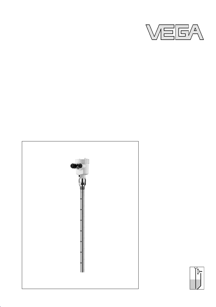
VEGAFLEX 65 is a level sensor with pipe probe for continuous
level measurement.
It is designed for industrial use in all areas of process
technology and can be used in liquids.
High frequency microwave pulses are guided along a steel
rope or a rod.Upon reaching the product surface,the
microwave pulses are reflected.The running time is evaluated
by the instrument and outputted as distance.
Power is supplied via the H1Fieldbus.Atwo-wire cable
according to Fieldbus specification serves as carrier of both
power and digital data for multiple sensors.This cable can be
operated in two versions:
lvia an H1interface card in the control system and
additional power supply
lvia a Linking device with HSE (High speed Ethernet)and
additional power supply according to IEC 61158-2
The DD (Device Descriptions)and CFF (capability files)
necessary for planning and configuration of your FF (Founda-
tion Fieldbus)communication network are available in the
download area of the VEGA homepage www.vega.com under
"Services -Downloads -Software -Foundation Fieldbus".The
appropriate certificates are also available there.A CD with the
appropriate files and certificates can be ordered via e-mail
under info@de.vega.com or by phone from one of the VEGA
agencies under the order number "DRIVER.S".
The optional heating requires its own power supply.You can
find further details in the supplementary instructions manual
"Heating for indicating and adjustment module".
3.3Operation
VEGAFLEX 65 can be adjusted with different adjustment
media:
Application range
Functional principle
Power supply and bus
communication
DD/CFF
VEGAFLEX 65 •Foundation Fieldbus 9
3Product description
31848-EN-080716

lwith indicating and adjustment module
lwith the suitable VEGA DTM in conjunction with an
adjustment software according to the FDT/DTM standard,
e.g.PACTware and PC
la configuration tool
The entered parameters are generally saved in VEGAFLEX
65,optionally also in the indicating and adjustment module or
in PACTware.
3.4Packaging,transport and storage
Your instrument was protected by packaging during transport.
Its capacity to handle normal loads during transport is assured
by a test according to DIN EN 24180.
The packaging of standard instruments consists of environ-
ment-friendly,recyclable cardboard.For special versions,PE
foam or PE foil is also used.Dispose of the packaging material
via specialised recycling companies.
Transport must be carried out under consideration of the notes
on the transport packaging.Nonobservance of these instruc-
tions can cause damage to the device.
The delivery must be checked for completeness and possible
transit damage immediately at receipt.Ascertained transit
damage or concealed defects must be appropriately dealt
with.
Up to the time of installation,the packages must be left closed
and stored according to the orientation and storage markings
on the outside.
Unless otherwise indicated,the packages must be stored only
under the following conditions:
lNot in the open
lDry and dust free
lNot exposed to corrosive media
lProtected against solar radiation
lAvoiding mechanical shock and vibration
lStorage and transport temperature see "Supplement -
Technical data -Ambient conditions"
lRelative humidity 20 …85 %
Packaging
Transport
Transport inspection
Storage
Storage and transport
temperature
10 VEGAFLEX 65 •Foundation Fieldbus
3Product description
31848-EN-080716

4Mounting
4.1General instructions
Select an installation position you can easily reach for
mounting and connecting as well as later retrofitting of an
indicating and adjustment module.The housing can be rotated
by 330°without the use of any tools.You can also install the
indicating and adjustment module in four different positions
(each displaced by 90°).
Before beginning the welding work,remove the oscillator
(electronics)from the sensor.By doing this,you avoid damage
to the electronics through inductive coupling.
With threaded versions,the housing must not be used to screw
in the instrument!Applying tightening forces on the housing
can damage its internal parts.
Use the hexagon for screwing in.
Use the recommended cables (see chapter "Connecting to
power supply")and tighten the cable gland.
You can give your instrument additional protection against
moisture penetration by leading the connection cable down-
ward in front of the cable entry.Rain and condensation water
can thus drain off.This applies mainly to outdoor mounting as
well as installation in areas where high humidity is expected (e.
g.through cleaning processes)or on cooled or heated
vessels.
Fig.2:Measures against moisture penetration
The reference plane for the measuring range of the sensors is
the seal surface of the thread.
Mounting position
Welding work
Handling
Moisture
Measuring range
VEGAFLEX 65 •Foundation Fieldbus 11
4Mounting
31848-EN-080716

Keep in mind that a min.distance must be maintained below
the reference plane and possibly also at the end of the probe -
measurement in these areas is not possible.These min.
distances are listed in chapter "Technical data"in the
"Supplement".
The process fitting must be sealed if there is gauge or low
pressure in the vessel.Before use,check if the seal material is
resistant against the measured product and the process
temperature.
The max.permissible pressure is specified in chapter
"Technical data"or on the type label of the sensor.
4.2Mounting instructions
Mount VEGAFLEX 65 in such a way that the probe does not
touch any installations or the vessel wall during installation.
In vessels with conical bottom it can be advantageous to
mount the sensor in the center of the vessel,as measurement
is then possible down to the lowest point of the vessel bottom.
Fig.3:Vessel with conical bottom
Make sure that the probe is not subjected to strong lateral
forces.Mount VEGAFLEX 65 at a position in the vessel where
no disturbances,e.g.from filling openings,agitators,etc., can
occur.
Pressure
Mounting position
Inflowing medium
12 VEGAFLEX 65 •Foundation Fieldbus
4Mounting
31848-EN-080716

Fig.4:Lateral load
Excessive system vibration or shocks,e.g.caused by agitators
or turbulence in the vessel (e.g.from fluidisation)can cause
the coax probe of VEGAFLEX 65 to vibrate in resonance.
Should a coax probe of more than 1m(3.281 in)length should
be used,you can provide a suitable support or guy directly
above the end of the probe to stabilise it.
VEGAFLEX 65 •Foundation Fieldbus 13
4Mounting
31848-EN-080716

5Connecting to power supply
5.1Preparing the connection
Always keep in mind the following safety instructions:
lConnect only in the complete absence of line voltage
lIf overvoltage surges are expected,overvoltage arresters
should be installed according to Foundation Fieldbus
specification
Tip:
We recommend VEGA overvoltage arrester B63-32.
In hazardous areas you should take note of the appropriate
regulations,conformity and type approval certificates of the
sensors and power supply units.
The instrument requires a supply voltage of 9…32 V DC.
Power and the digital bus signal are carried on the same two-
wire connection cable.Power is supplied via the H1power
supply.
Connection is carried out with screened cable according to
Fieldbus specification.
Use cable with round cross-section.Acable outer diameter of
5…9mm (0.2…0.35 in)ensures the seal effect of the cable
gland.If you are using cable with other diameter or cross-
section,you have to exchange the seal or use a suitable cable
gland.
Make sure that the entire installation is carried out according to
the Fieldbus specification.In particular,make sure that the
termination of the bus is done with appropriate terminating
resistors.
On the instrument with cable entry ½NPT and plastic housing
there is a metallic ½" threaded insert moulded into the plastic
housing.
Caution:
No grease should be used when screwing the NPT cable
gland or steel tube into the threaded insert.Standard grease
can contain additives that corrode the connection between
threaded insert and housing.This would influence the stability
of the connection and the tightness of the housing.
Note safety instructions
Take note of
safety instruc-
tions for Ex ap-
plications
Select power supply
Selecting connection
cable
Cable gland ½NPT
14 VEGAFLEX 65 •Foundation Fieldbus
5Connecting to power supply
31848-EN-080716

In systems with potential equalisation,connect the cable
screen directly to ground potential at the power supply unit,in
the connection box and at the sensor.The screen in the sensor
must be connected directly to the internal ground terminal.The
ground terminal outside on the housing must be connected to
the potential equalisation (low impedance).
In systems without potential equalisation,connect the cable
screen directly to ground potential at the power supply unit and
at the sensor.In the connection box or T-distributor,the screen
of the short stub to the sensor must not be connected to
ground potential or to another cable screen.The cable screens
to the power supply unit and to the next distributor must be
connected to each other and also connected to ground
potential via a ceramic capacitor (e.g.1nF,1500 V). The low
frequency potential equalisation currents are thus suppressed,
but the protective effect against high frequency interference
signals remains.
The total capacitance of the cable and of all capacitors must
not exceed 10 nFin Ex applications.
Take note of the corresponding installation regulations for Ex
applications.In particular,make sure that no potential equal-
isation currents flow over the cable screen.In case of
grounding on both sides this can be achieved by the use of a
capacitor or a separate potential equalisation.
5.2Connection steps -Instrument housing
Proceed as follows:
1Unscrew the housing cover
2If an indicating and adjustment module is installed,remove
it by turning it slightly to the left.
3Loosen compression nut of the cable entry
4Remove approx.10 cm (4in)of the cable mantle,strip
approx.1cm (0.4in)insulation from the ends of the
individual wires
5Insert the cable through the cable gland into the sensor
6Lift the opening levers of the terminals with a screwdriver
(see following illustration)
Cable screening and
grounding
Select connec-
tion cable for Ex
applications
VEGAFLEX 65 •Foundation Fieldbus 15
5Connecting to power supply
31848-EN-080716

7Insert the wire ends into the open terminals according to
the wiring plan
Fig.5:Connection steps 6and 7
8Press down the opening levers of the terminals,you will
hear the terminal spring closing
9Check the hold of the wires in the terminals by lightly
pulling on them
10 Connect the screen to the internal ground terminal,connect
the outer ground terminal with potential equalisation
11 Tighten the compression nut of the cable entry.The seal
ring must completely encircle the cable
12 Screw the housing cover on
The electrical connection is finished.
5.3Wiring plan,single chamber housing
The following illustrations apply to the non-Ex as well as to the
Ex-ia version.
16 VEGAFLEX 65 •Foundation Fieldbus
5Connecting to power supply
31848-EN-080716

5
5
55
1 2
4
3
Fig.6:Material versions,single chamber housing
1Plastic
2Aluminium
3Stainless steel,investment casting
4Stainless steel,electro-polished
5Filter element for air pressure compensation of all material versions.Blind
stopper with version IP 66/IP 68,1bar for Aluminium and stainless steel
I2C
3
4
51
2
Display
Ty p :
1 2 5 6 7 8
Bus
Sim.
Fig.7:Electronics and connection compartment,single chamber housing
1Plug connector for VEGACONNECT (I²Cinterface)
2Spring-loaded terminals for connection of the external indication VEGADIS
61
3Ground terminal for connection of the cable screen
4Spring-loaded terminals for Foundation Fieldbus connection
5Simulation switch ("on" = mode for simulation release)
Housing overview
Electronics and connec-
tion compartment
VEGAFLEX 65 •Foundation Fieldbus 17
5Connecting to power supply
31848-EN-080716

I2C
Display
1
1 2 5 6 7 8
Fig.8:Wiring plan,single chamber housing
1Voltage supply/Signal output
5.4Wiring plan,double chamber housing
The following illustrations apply to the non-Ex as well as to the
Ex-ia version.
1 2 3
45
Fig.9:Double chamber housing
1Housing cover,connection compartment
2Blind stopper or plug M12 x1for VEGADIS 61 (optional)
3Housing cover,electronics compartment
4Filter element for air pressure compensation
5Cable gland
Wiring plan
Housing overview
18 VEGAFLEX 65 •Foundation Fieldbus
5Connecting to power supply
31848-EN-080716

I2C
2
3
1
Display
Ty p :
1 2 5 6 7 8
Bus
Sim.
Fig.10:Electronics compartment,double chamber housing
1Simulation switch ("on" = mode for simulation release)
2Connection for VEGACONNECT (I²Cinterface)
3Internal connection cable to the connection compartment
3
1
2
Display
1 2 I²C
Fig.11:Connection compartment,double chamber housing
1Plug connector for VEGACONNECT (I²Cinterface)
2Ground terminal for connection of the cable screen
3Spring-loaded terminals for voltage supply
Electronics compart-
ment
Connection compart-
ment
VEGAFLEX 65 •Foundation Fieldbus 19
5Connecting to power supply
31848-EN-080716

I2C
1
1 2
Fig.12:Wiring plan,double chamber housing
1Voltage supply/Signal output
5.5Wiring plan -version IP 66/IP 68,1bar
+
-
1
2
Fig.13:Wire assignment,connection cable
1brown (+)and blue (-) to power supply or to the processing system
2Shielding
Wiring plan
Wire assignment,con-
nection cable
20 VEGAFLEX 65 •Foundation Fieldbus
5Connecting to power supply
31848-EN-080716
Other manuals for VEGAFLEX 65
4
Table of contents
Other Vega Accessories manuals

Vega
Vega VEGACAP 64 User manual

Vega
Vega VEGAFLEX 62 User manual

Vega
Vega vegaflex 83 User manual

Vega
Vega VEGAFLEX 81 User manual

Vega
Vega VEGAFLEX 81 User manual

Vega
Vega VEGAFLEX 81 User manual

Vega
Vega VEGAPULS 69 User manual

Vega
Vega VEGAPULS WL 61 User manual

Vega
Vega VEGAPULS Air 41 User manual

Vega
Vega VEGAFLEX 67 User manual

Vega
Vega VEGAVIB 62 User manual

Vega
Vega SOLITRAC 31 User manual

Vega
Vega VEGAPULS 69 User manual

Vega
Vega VEGAPULS 63 User manual

Vega
Vega vegaflex 83 User manual

Vega
Vega MINITRAC 31 User manual

Vega
Vega VEGASON S 61 User manual

Vega
Vega VEGADIS 81 User manual

Vega
Vega VEGAFLEX 82 User manual

Vega
Vega VEGABAR 82 User manual