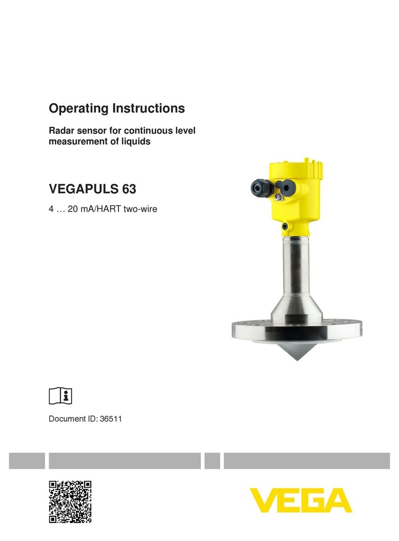
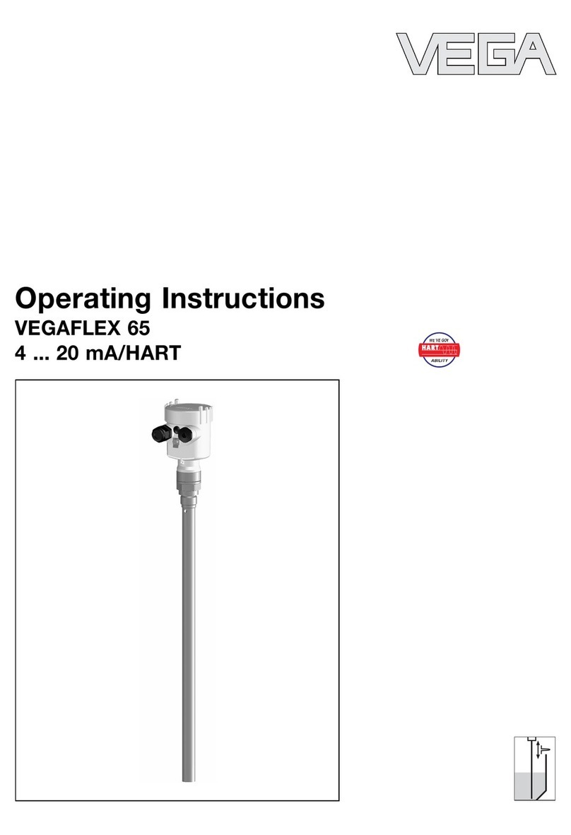
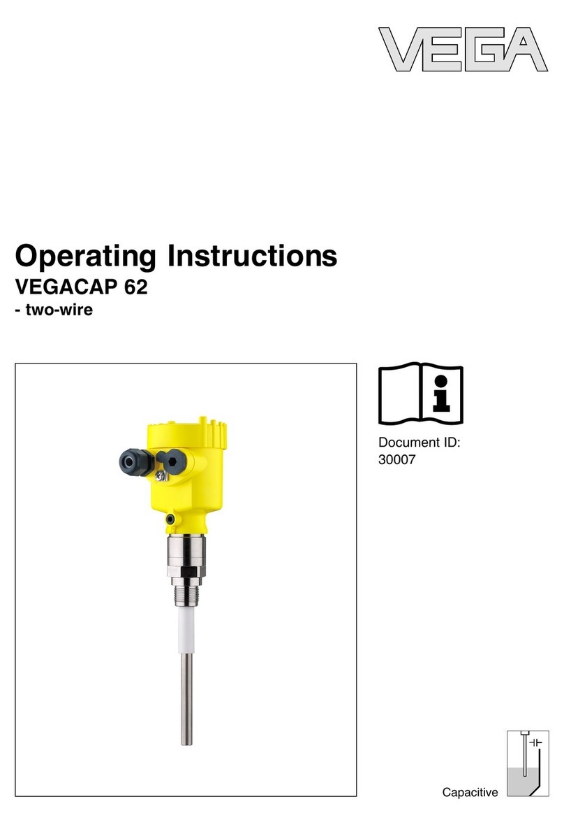
Vega VEGAPULS WL 61 User manual

Quick setup guide
Radar sensor for continuous level
measurement of water and wastewater
VEGAPULS WL 61
4 … 20 mA/HART - two-wire
Document ID: 47095

2
Contents
VEGAPULS WL 61 • 4 … 20 mA/HART - two-wire
47095-EN-180702
Contents
1 For your safety ......................................................................................................................... 3
1.1 Authorised personnel ....................................................................................................... 3
1.2 Appropriate use................................................................................................................ 3
1.3 Warning about incorrect use............................................................................................. 3
1.4 General safety instructions............................................................................................... 3
1.5 EU conformity................................................................................................................... 4
1.6 NAMUR recommendations .............................................................................................. 4
1.7 Radio licenses for Europe ................................................................................................ 4
1.8 Radio approval for USA.................................................................................................... 5
1.9 Radio approval for Canada............................................................................................... 5
1.10 Environmental instructions ............................................................................................... 7
2 Product description ................................................................................................................. 8
2.1 Conguration.................................................................................................................... 8
2.2 Adjustment ....................................................................................................................... 9
3 Mounting................................................................................................................................. 11
3.1 Mounting versions.......................................................................................................... 11
3.2 Mounting preparations, mounting strap.......................................................................... 14
4 Connecting to power supply................................................................................................. 15
4.1 Wiring plan ..................................................................................................................... 15
5 Setup with smartphone/tablet (Bluetooth).......................................................................... 16
5.1 Connecting..................................................................................................................... 16
5.2 Sensor parameter adjustment........................................................................................ 17
5.3 Adjustment ..................................................................................................................... 17
6 Setup with VEGADIS 82......................................................................................................... 19
6.1 Principle of operation and connection ............................................................................ 19
6.2 Adjustment volume......................................................................................................... 19
6.3 Setup steps .................................................................................................................... 20
7 Setup with PACTware............................................................................................................. 21
7.1 Connect the PC.............................................................................................................. 21
7.2 Parameter adjustment with PACTware............................................................................ 22
8 Supplement ............................................................................................................................ 24
8.1 Technical data ................................................................................................................ 24
Information:
This quick setup guide enables quick setup and commissioning of
your instrument.
Youcanndsupplementaryinformationinthecorresponding,more
detailed Operating Instructions Manual as well as the Safety Manual
thatcomeswithinstrumentswithSILqualication.Thesemanualsare
available in the download area of "www.vega.com".
Operating instructions VEGAPULS WL 61 - 4 … 20 mA/HART -
two-wire: Document-ID 38061
Editing status of the quick setup guide: 2018-06-29

3
1 For your safety
VEGAPULS WL 61 • 4 … 20 mA/HART - two-wire
47095-EN-180702
1 For your safety
1.1 Authorised personnel
All operations described in this documentation must be carried out
only by trained specialist personnel authorised by the plant operator.
During work on and with the device the required personal protective
equipment must always be worn.
1.2 Appropriate use
VEGAPULS WL 61 is a sensor for continuous level measurement.
Youcannddetailedinformationabouttheareaofapplicationin
chapter "Product description".
Operational reliability is ensured only if the instrument is properly
usedaccordingtothespecicationsintheoperatinginstructions
manual as well as possible supplementary instructions.
1.3 Warning about incorrect use
Inappropriate or incorrect use of this product can give rise to applica-
tion-specichazards,e.g.vesseloverllthroughincorrectmounting
or adjustment. Damage to property and persons or environmental
contamination can result. Also, the protective characteristics of the
instrument can be impaired.
1.4 General safety instructions
This is a state-of-the-art instrument complying with all prevailing
regulations and directives.The instrument must only be operated in a
technicallyawlessandreliablecondition.Theoperatorisresponsi-
ble for the trouble-free operation of the instrument. When measuring
aggressive or corrosive media that can cause a dangerous situation
if the instrument malfunctions, the operator has to implement suitable
measures to make sure the instrument is functioning properly.
During the entire duration of use, the user is obliged to determine the
compliance of the necessary occupational safety measures with the
current valid rules and regulations and also take note of new regula-
tions.
The safety instructions in this operating instructions manual, the na-
tional installation standards as well as the valid safety regulations and
accident prevention rules must be observed by the user.
For safety and warranty reasons, any invasive work on the device
beyond that described in the operating instructions manual may be
carried out only by personnel authorised by the manufacturer. Arbi-
traryconversionsormodicationsareexplicitlyforbidden.Forsafety
reasons,onlytheaccessoryspeciedbythemanufacturermustbe
used.
To avoid any danger, the safety approval markings and safety tips on
the device must also be observed and their meaning read in this oper-
ating instructions manual.

4
1 For your safety
VEGAPULS WL 61 • 4 … 20 mA/HART - two-wire
47095-EN-180702
Depending on the instrument version, the emitting frequencies are in
the C, K or W band range. The low emission power is far below the
internationally approved limit values. When used correctly, the device
poses no danger to health.
1.5 EU conformity
ThedevicefullsthelegalrequirementsoftheapplicableEUdirec-
tives.ByaxingtheCEmarking,weconrmtheconformityofthe
instrument with these directives.
YoucanndtheEUconformitydeclarationonourwebsiteunder
www.vega.com/downloads.
1.6 NAMUR recommendations
NAMUR is the automation technology user association in the process
industry in Germany. The published NAMUR recommendations are
acceptedasthestandardineldinstrumentation.
ThedevicefullstherequirementsofthefollowingNAMURrecom-
mendations:
• NE 43 – Signal level for fault information from measuring transduc-
ers
• NE53–Compatibilityofelddevicesanddisplay/adjustment
components
• NE107-Self-monitoringanddiagnosisofelddevices
For further information see www.namur.de.
1.7 Radio licenses for Europe
VEGAPULS WL 61
The instrument was tested according to the latest issue of the follow-
ingharmonizedstandards:
• EN 302372 - Tank Level Probing Radar
• EN 302729 - Level Probing Radar
It is hence approved for use inside and outside closed vessels in
countries of the EU.
Use is also approved in EFTA countries, provided the respective
standards have been implemented.
Foroperationinsideofclosedvessels,pointsatofinannexEof
EN302372mustbefullled.
For operation outside of closed vessels, the following conditions must
befullled:
• Theinstallationmustbecarriedoutbytrainedqualiedpersonnel
• The instrument must be stationary mounted and the antenna
directed vertically downward
• The mounting location must be at least 4 km away from radio
astronomy stations, unless special permission was granted by the
responsible national approval authority

5
1 For your safety
VEGAPULS WL 61 • 4 … 20 mA/HART - two-wire
47095-EN-180702
• When installed within 4 to 40 km of a radio astronomy station,
the instrument must not be mounted higher than 15 m above the
ground.
Youcanndalistoftherespectiveradioastronomystationsinchap-
ter "Supplement".
Bluetooth radio module
The radio module used in the instrument for wireless Bluetooth com-
munication was tested by the manufacturer according to the latest
edition of the following standard:
• EN 300328 – Wideband transmission systems
It is hence for use inside closed vessels in countries of the EU and
EFTA.
1.8 Radio approval for USA
ThisapprovalisonlyvalidforUSA.Hencethefollowingtextisonly
available in English language.
This device complies with Part 15 of the FCC Rules.
Operation is subject to the following conditions:
• This device may not cause interference, and
• This device must accept any interference, including interference
that may cause undesired operation of the device
This device has been approved for open air environments with the
following limitations:
• This device shall be installed and maintained to ensure a verti-
cally downward orientation of the transmit antenna's main beam.
Furthermore, the use of any mechanism that does not allow the
main beam of the transmitter to be mounted vertically downward is
prohibited.
• Thisdeviceshallbeinstalledonlyatxedlocations.TheLPR
device shall not operate while being moved or while inside a mov-
ing container.
• Hand-held applications are prohibited.
• Marketing to residential consumers is prohibited.
Changesormodicationsnotexpresslyapprovedbythemanufac-
turer could void the user’s authority to operate this equipment.
1.9 Radio approval for Canada
ThisapprovalisonlyvalidforCanada.Hencethefollowingtextsare
only available in English/French language.
ThisdevicecomplieswithIndustryCanada'slicense-exemptRSS
standard(s).
Operation is subject to the following conditions:
• This device may not cause interference, and
• This device must accept any interference, including interference
that may cause undesired operation of the device

6
1 For your safety
VEGAPULS WL 61 • 4 … 20 mA/HART - two-wire
47095-EN-180702
This device has been approved for open air environments with the
following limitations:
• This device shall be installed and maintained to ensure a verti-
cally downward orientation of the transmit antenna's main beam.
Furthermore, the use of any mechanism that does not allow the
main beam of the transmitter to be mounted vertically downward is
prohibited.
• The installation of the LPR/TLPR device shall be done by trained
installers, in strict compliance with the manufacturer's instructions.
• Thisdeviceshallbeinstalledonlyatxedlocations.TheLPR
device shall not operate while being moved or while inside a mov-
ing container.
• Hand-held applications are prohibited.
• Marketing to residential consumers is prohibited.
• The use of this device is on a "no-interference, no-protection"
basis.That is, the user shall accept operations of high-powered
radar in the same frequency band which may interfere with or
damage this device.
• However, devices found to interfere with primary licensing opera-
tionswillberequiredtoberemovedattheuser'sexpense.
LeprésentappareilestconformeauxCNRd’IndustrieCanadaap-
plicablesauxappareilsradioexemptsdelicence.L’exploitationest
autoriséeauxconditionssuivantes:
• L’appareil ne doit pas produire de brouillage; et
• L’utilisateur de l’appareil doit accepter tout brouillage radioélect-
rique subi, même si le brouillage est susceptible d’en compromet-
tre le fonctionnement.
Cet appareil est homologué pour une utilisation dans les environne-
ments ouverts avec les restrictions suivantes :
• L'appareil doit être installé et entretenu de manière à garantir une
orientation verticale vers le bas du faisceau principal de l’antenne
émettrice. De plus, l’utilisation de tout mécanisme ne permettant
pas l’orientation verticale vers le bas du faisceau principal de
l’émetteur est interdite
• L’installationd’undispositifLPRouTLPRdoitêtreeectuée
pardesinstallateursqualiés,enpleineconformitéavecles
instructions du fabricant.
• Cetappareilnedoitêtreinstalléqu'àdesemplacementsxes.
L’appareil LPR ne doit pas être utilisé pendant qu’il est en train
d’être déplacé ou se trouve dans un conteneur en mouvement.
• Les applications portables sont interdites.
• La vente à des particuliers est interdite
• Cedispositifnepeutêtreexploitéqu'enrégimedenon-brouillage
et de non-protection, c'est-à-dire que l'utilisateur doit accepter que
des radars de haute puissance de la même bande de fréquences
puissent brouiller ce dispositif ou même l'endommager.
• D'autrepart,lescapteursdeniveauquiperturbentuneexploita-
tion autorisée par licence de fonctionnement principal doivent être
enlevésauxfraisdeleurutilisateur.

7
1 For your safety
VEGAPULS WL 61 • 4 … 20 mA/HART - two-wire
47095-EN-180702
1.10 Environmental instructions
Protection of the environment is one of our most important duties.
That is why we have introduced an environment management system
with the goal of continuously improving company environmental pro-
tection.Theenvironmentmanagementsystemiscertiedaccording
to DIN EN ISO 14001.
Pleasehelpusfullthisobligationbyobservingtheenvironmental
instructions in this manual:
• Chapter "Packaging, transport and storage"
• Chapter "Disposal"

8
2 Product description
VEGAPULS WL 61 • 4 … 20 mA/HART - two-wire
47095-EN-180702
2 Product description
2.1 Conguration
Youcanndthetypelabelonthesensorhousingaswellasonthe
type label support on the connection cable.
Itcontainsthemostimportantdataforidenticationanduseofthe
instrument.
2
1
15
16
13
14
12
11
5
3
6
4
7
8
10
9
Fig. 1: Layout of the type label (example)
1 Instrument type
2 Product code
3 Approvals
4 Power supply and signal output, electronics
5 Protection rating
6 Measuring range (measurement reliability optional)
7 Process and ambient temperature, process pressure
8 Material wetted parts
9 Hardware and software version
10 Order number
11 Serial number of the instrument
12 Data matrix code for VEGA Tools app
13 Symbol of the device protection class
14 ID number, instrument documentation
15 Reminder to observe the instrument documentation
16 Symbol for Bluetooth
The 4-digit PIN is necessary for the Bluetooth connection to the sen-
sor.The PIN is unique and is only valid of this sensor.
YoucanndthePINasalabelonasupplementarysheetinthesen-
sorpackagingandnexttothetypelabel.
Fig. 2: Bluetooth PIN
Type label
Sensor PIN

9
2 Product description
VEGAPULS WL 61 • 4 … 20 mA/HART - two-wire
47095-EN-180702
The type label contains the serial number of the instrument. With it
youcanndthefollowinginstrumentdataonourhomepage:
• Product code (HTML)
• Delivery date (HTML)
• Order-specicinstrumentfeatures(HTML)
• Operating instructions and quick setup guide at the time of ship-
ment (PDF)
• Order-specicsensordataforanelectronicsexchange(XML)
• Testcerticate(PDF)-optional
Go to "www.vega.com", "Instrument search (serial number)". Enter
the serial number.
Alternatively, you can access the data via your smartphone:
• Download the VEGA Tools app from the "Apple App Store" or the
"Google Play Store"
• ScantheDataMatrixcodeonthetypelabeloftheinstrumentor
• Enter the serial number manually in the app
2.2 Adjustment
Adjustment via the signal cable
As a standard feature, VEGAPULS WL 61 allows an adjustment via:
• ExternaldisplayandadjustmentunitVEGADIS82(PLICSCOM)
• PC/Notebook with interface adapter VEGACONNECT (adjustment
software PACTware)
• DD adjustment programs
• Field Communicator 375, 475
4
5
3
1
2
Fig. 3: Connection of the VEGADIS 82 to the sensor, adjustment via the display
and adjustment module
1 Voltage supply/Signal output sensor
2 VEGADIS 82
3 Display and adjustment module
4 4 … 20 mA/HART signal cable
5 Sensor
Wireless adjustment
VEGAPULS WL 61 with integrated Bluetooth module enables the
wireless adjustment via standard adjustment instruments:
Serial number - Instru-
ment search

10
2 Product description
VEGAPULS WL 61 • 4 … 20 mA/HART - two-wire
47095-EN-180702
• Smartphone/tablet (iOS or Android operating system)
• PC/notebook with Bluetooth USB adapter (Windows operating
system)
1
4
2
3
Fig. 4: Wireless connection to standard operating devices
1 Display and adjustment module
2 Sensor
3 Smartphone/Tablet
4 Bluetooth USB adapter
5 PC/Notebook

11
3 Mounting
VEGAPULS WL 61 • 4 … 20 mA/HART - two-wire
47095-EN-180702
3 Mounting
3.1 Mounting versions
Most simply mount the instrument via the straining clamp. For this
purpose, the connection cable is provided with a strain relief wire of
Kevlar.
In order to avoid faulty measured values, make sure that the sensor
does not oscillate.
> 200 mm
(7.87")
Fig. 5: Mounting via a straining clamp
For a rigid mounting, a mounting bracket with opening for thread
G1½, e.g. from the VEGA product range, is recommended. The
mounting of the sensor in the bracket is carried out via a G1½ counter
nut of plastic.Take note of chapter "Mounting instructions" for the
distance to the wall.
Straining clamp
Mounting bracket

12
3 Mounting
VEGAPULS WL 61 • 4 … 20 mA/HART - two-wire
47095-EN-180702
> 200 mm
(7.87
")
Fig. 6: Mounting via a mounting bracket
The optional mounting strap enables sensor mounting on e.g. a ceil-
ing, wall or bracket. It is available in the following versions:
• Length 300 mm for ceiling mounting
• Length 170 mm for wall mounting
The instrument is normally mounted vertically with a bracket on the
ceiling.
This ensures swivelling of the sensor up to 180° for optimum orienta-
tion.
Fig. 7: Ceiling mounting via the mounting strap with length 300 mm
Mounting strap
Mounting strap - Ceiling
mounting

13
3 Mounting
VEGAPULS WL 61 • 4 … 20 mA/HART - two-wire
47095-EN-180702
Fig. 8: Rotation in the centre with ceiling mounting
Asanalternativethestrapmountingiscarriedouthorizontallyor
obliquely.
> 200 mm
(7.87")
Fig. 9: Wall mounting via the mounting strap with length 170 mm
Fig. 10: Wall mounting with inclined wall via the mounting strap with length
300 mm
For mounting the instrument on a socket or a manhole cover, an
unassembledcombicollarangeforDN80(ASME3"orJIS80)is
optionallyavailablealsoasretrottingpart.
Mounting strap - Wall
mounting
Flange mounting

14
3 Mounting
VEGAPULS WL 61 • 4 … 20 mA/HART - two-wire
47095-EN-180702
Youcannddrawingsofthesemountingoptionsinchapter"Dimen-
sions".
Fig. 11: Mounting by means of an adapter ange, for example, on a manhole lid.
3.2 Mounting preparations, mounting strap
The optional mounting strap is supplied unassembled. It must be
screwedtothesensorbeforesetupwiththeattachedscrews.Max.
torque, see chapter "Technical data". Required tools: Allen wrench
size4.
Therearetwodierentvariantsofscrewingthestraptothesensor.
Depending on the selected variant, the sensor can be rotated in the
strapinnitelyvariablethrough180°orinthreesteps0°,90°and
180°.

15
4 Connecting to power supply
VEGAPULS WL 61 • 4 … 20 mA/HART - two-wire
47095-EN-180702
4 Connecting to power supply
4.1 Wiring plan
1
2
Fig. 12: Wire assignment in permanently connected connection cable
1 Brown (+) and blue (-) to power supply or to the processing system
2 Shielding
Wire assignment, con-
nection cable

16
5 Setup with smartphone/tablet (Bluetooth)
VEGAPULS WL 61 • 4 … 20 mA/HART - two-wire
47095-EN-180702
5 Setup with smartphone/tablet (Bluetooth)
5.1 Connecting
Start the "VEGA Tools" app and select the function "Setup". The
smartphone/tablet searches automatically for Bluetooth-capable
instruments in the area.
The message "Searching …" is displayed.
The found instruments will be listed on the left side of the adjustment
window.The search is continued automatically.
Select the requested instrument in the device list.
The message "Connecting …" is displayed.
Fortherstconnection,theoperatingdeviceandthesensormust
authenticateeachother.Aftersuccessfulauthentication,thenextcon-
nection functions without authentication.
iOS
During the pairing process, the following message is displayed: "Pair-
ing request (Bluetooth), e.g. 12345678 wants to pair with your iPad".
Press "Pair".
Android
The coupling passes through automatically.
Forauthentication,enterinthenextmenuwindowthe4-digitPIN.You
canndthisPINon:
• Type label support on sensor cable
• A supplementary sheet in the sensor packaging
Note:
If an incorrect sensor PIN is entered, the PIN can only be entered
again after a delay time. This time gets longer after each incorrect
entry.
The message "Waiting for authentication" is displayed on the smart-
phone/tablet.
After connection, the sensor adjustment menu is displayed on the
respective adjustment instrument.
If the connection is interrupted, e.g. due to a too large distance be-
tween sensor and operating device, this is displayed on the operating
device.The message disappears when the connection is restored.
It is recommended to change the default setting of the sensor PIN to
your own sensor PIN. To do this, go to the menu item "Lock adjust-
ment".
Connecting …
Authenticate
Enter PIN
Connected
Change sensor PIN

17
5 Setup with smartphone/tablet (Bluetooth)
VEGAPULS WL 61 • 4 … 20 mA/HART - two-wire
47095-EN-180702
After the sensor PIN has been changed, sensor adjustment can be
enabled again. For access (authentication) with Bluetooth, the PIN is
stilleective.
5.2 Sensor parameter adjustment
The sensor adjustment menu is divided into two halves:
Ontheleftyou'llndthenavigationsectionwiththemenus"Setup",
"Display", "Diagnosis" and others.
The selected menu item, recognisable by the colour change, is dis-
played in the right half.
Fig. 14: Example of an app view - Setup sensor adjustment
Entertherequestedparametersandconrmviathekeyboardorthe
editingeld.Thesettingsarethenactiveinthesensor.
Close the app to terminate connection.
5.3 Adjustment
Since a radar sensor is a distance measuring instrument, the distance
from the sensor to the product surface is measured. For indication of
the real level, an allocation of the measured distance to the percent-
age height must be carried out.To perform the adjustment, enter the
distancewithfullandemptyvessel,seethefollowingexample:
Enter parameters

18
5 Setup with smartphone/tablet (Bluetooth)
VEGAPULS WL 61 • 4 … 20 mA/HART - two-wire
47095-EN-180702
2
3
1
0,5 m
(19.68
")
5 m
(196.85
")
100%
0%
Fig. 15: Parameterization example
1 Min. level = max. measuring distance
2 Max. level = min. measuring distance
If these values are not known, an adjustment with the distances of for
example10%and90%ispossible.Startingpointforthesedistance
specicationsisalwaysthesealsurfaceofthethreadorange.By
means of these settings, the real level will be calculated.
The actual product level during this adjustment is not important,
becausethemin./max.adjustmentisalwayscarriedoutwithout
changing the product level.These settings can be made ahead of
time without the instrument having to be installed.

19
6 Setup with VEGADIS 82
VEGAPULS WL 61 • 4 … 20 mA/HART - two-wire
47095-EN-180702
6 Setup with VEGADIS 82
6.1 Principle of operation and connection
TheVEGADIS82isanexternaldisplayandadjustmentunitwithout
additionalexternalenergy.
The instrument is suitable for measured value indication and adjust-
ment of sensors with HART protocol. It can be connected at any point
tothe4…20mAsignalcable.Aseparateexternalenergyisnot
required.
4
5
3
1
2
Fig. 16: Connection of the VEGADIS 82 to the sensor, adjustment via the dis-
play and adjustment module
1 Voltage supply/Signal output sensor
2 VEGADIS 82
3 Display and adjustment module
4 4 … 20 mA/HART signal cable
5 Sensor
6.2 Adjustment volume
Main menu: Setup, Diagnosis, Additional adjustments, Info
Setup:Settings,forexample,formedium,application,vesselform,
adjustment, signal output
Diagnosis:Information,forexampleontheinstrumentstatus,peak
value, measurement reliability, echo curve memory as well as simula-
tion

20
6 Setup with VEGADIS 82
VEGAPULS WL 61 • 4 … 20 mA/HART - two-wire
47095-EN-180702
Additional adjustment:Falsesignalsuppression,linearization,reset
Info: Instrument type and serial number
6.3 Setup steps
YoucanndadetaileddescriptionofthesetupstepsforVEGAPULS
WL 61 in the operating instructions manual "VEGADIS 82 -
4 … 20 mA/HART".
Other manuals for VEGAPULS WL 61
10
Table of contents
Other Vega Accessories manuals

Vega
Vega VEGAFLEX 82 User manual

Vega
Vega VEGAPULS 66 User manual

Vega
Vega VEGAPULS 42 User manual

Vega
Vega VEGAPULS 66 User manual

Vega
Vega vegaflex 83 User manual

Vega
Vega VEGAFLEX 82 User manual

Vega
Vega VEGAPULS 67 User manual

Vega
Vega VEGACAP 64 User manual

Vega
Vega VEGAPULS 6X User manual

Vega
Vega VEGAFLEX 67 User manual

Vega
Vega VEGAPULS WL 61 User manual

Vega
Vega VEGAFLEX 86 User manual

Vega
Vega VEGAFLEX 62 User manual

Vega
Vega VEGABAR 82 User manual

Vega
Vega VEGAPULS C 21 User manual

Vega
Vega VEGAPULS 63 User manual

Vega
Vega VEGADIS 81 User manual

Vega
Vega vegaflex 83 User manual

Vega
Vega VEGAPULS 61 User manual

Vega
Vega MINITRAC 31 User manual