2
Contents
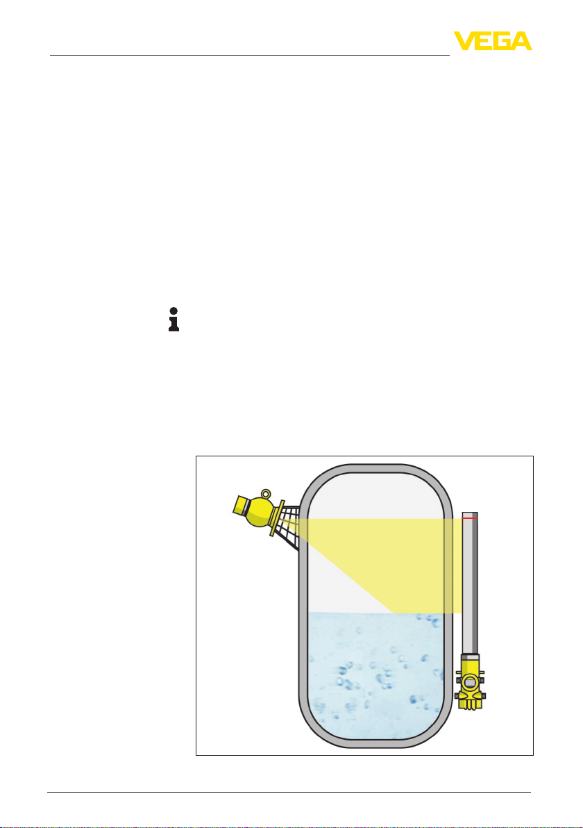
SOLITRAC 31 • Four-wire 4 … 20 mA/HART
62085-EN-211203
Contents
1 For your safety ......................................................................................................................... 3
1.1 Authorised personnel ....................................................................................................... 3
1.2 Appropriate use................................................................................................................ 3
1.3 Warning about incorrect use............................................................................................. 3
1.4 General safety instructions............................................................................................... 3
1.5 EU conformity................................................................................................................... 3
1.6 NAMUR recommendations .............................................................................................. 4
1.7 Installation and operation in the USA and Canada ........................................................... 4
1.8 Environmental instructions ............................................................................................... 4
2 Product description ................................................................................................................. 5
2.1 Conguration.................................................................................................................... 5
2.2 Principle of operation........................................................................................................ 6
2.3 System limitations ............................................................................................................ 6
2.4 Corresponding source container...................................................................................... 7
3 Mounting................................................................................................................................... 9
3.1 General instructions ......................................................................................................... 9
3.2 Mounting instructions ..................................................................................................... 10
4 Connecting to power supply................................................................................................. 14
4.1 Preparing the connection ............................................................................................... 14
4.2 Connection - Level measurement................................................................................... 16
4.3 Connection - Level detection.......................................................................................... 18
4.4 Connection - Summation................................................................................................ 20
5 Functional safety (SIL) .......................................................................................................... 22
5.1 Objective........................................................................................................................ 22
5.2 SILqualication.............................................................................................................. 22
5.3 Application area ............................................................................................................. 22
5.4 Safety concept of the parameterization .......................................................................... 23
6 Set up with the display and adjustment module ................................................................ 25
6.1 Insert display and adjustment module............................................................................ 25
6.2 Parameter adjustment - Summation Secondary............................................................. 25
7 Supplement ............................................................................................................................ 27
7.1 Technical data ................................................................................................................ 27
Information:
This quick setup guide enables quick setup and commissioning of
your instrument.
Youcanndsupplementaryinformationinthecorresponding,more
detailed Operating Instructions Manual as well as the Safety Manual
thatcomeswithinstrumentswithSILqualication.Thesemanualsare
available on our homepage.
Operating instructions SOLITRAC 31, four-wire 4 … 20 mA/
HART, with SIL qualication: Document-ID 43387
Editing status of the quick setup guide: 2021-11-25