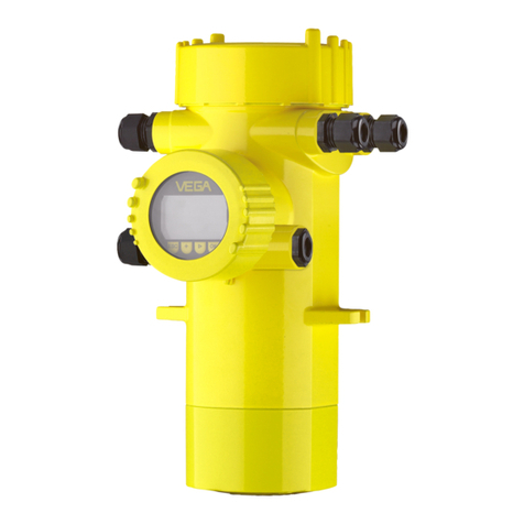
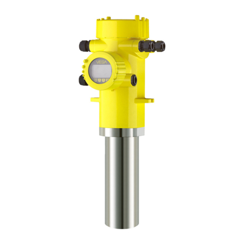
Vega vegaflex 83 User manual

Operating Instructions
TDR sensor for continuous level and
interface measurement of liquids
VEGAFLEX 83
Foundation Fieldbus
Polished rod probe
Document ID: 44224

2
Contents
VEGAFLEX 83 • Foundation Fieldbus
44224-EN-160518
Contents
1 About this document
1.1 Function ........................................................................................................................... 4
1.2 Target group ..................................................................................................................... 4
1.3 Symbols used................................................................................................................... 4
2 For your safety
2.1 Authorised personnel ....................................................................................................... 5
2.2 Appropriate use................................................................................................................ 5
2.3 Warning about incorrect use............................................................................................. 5
2.4 General safety instructions............................................................................................... 5
2.5 CE conformity................................................................................................................... 5
2.6 NAMUR recommendations .............................................................................................. 6
2.7 Environmental instructions ............................................................................................... 6
3 Product description
3.1 Conguration.................................................................................................................... 7
3.2 Principle of operation........................................................................................................ 8
3.3 Packaging, transport and storage................................................................................... 11
3.4 Accessories and replacement parts ............................................................................... 11
4 Mounting
4.1 General instructions ....................................................................................................... 14
4.2 Mounting instructions ..................................................................................................... 14
5 Connecting to power supply
5.1 Preparing the connection ............................................................................................... 21
5.2 Connecting..................................................................................................................... 22
5.3 Wiring plan, single chamber housing.............................................................................. 23
5.4 Wiring plan, double chamber housing ............................................................................ 24
5.5 Double chamber housing with DISADAPT ..................................................................... 26
5.6 Wiring plan - version IP 66/IP 68, 1 bar........................................................................... 27
5.7 Supplementary electronics............................................................................................. 27
5.8 Switch-on phase............................................................................................................. 27
6 Set up with the display and adjustment module
6.1 Insert display and adjustment module............................................................................ 28
6.2 Adjustment system......................................................................................................... 29
6.3 Parameter adjustment - Quick setup .............................................................................. 31
6.4 Parameter adjustment - Extended adjustment................................................................ 31
6.5 Saving the parameter adjustment data........................................................................... 46
7 Setup with PACTware
7.1 Connect the PC.............................................................................................................. 48
7.2 Parameter adjustment with PACTware............................................................................ 48
7.3 Set up with the quick setup............................................................................................. 49
7.4 Saving the parameter adjustment data........................................................................... 51
8 Set up with other systems
8.1 DD adjustment programs ............................................................................................... 52
8.2 Field Communicator 375, 475 ........................................................................................ 52
9 Diagnostics and servicing
9.1 Maintenance .................................................................................................................. 53
3
Contents
VEGAFLEX 83 • Foundation Fieldbus
44224-EN-160518
9.2 Diagnosis memory ......................................................................................................... 53

9.3 Status messages............................................................................................................ 54
9.4 Rectify faults................................................................................................................... 58
9.5 Exchanging the electronics module................................................................................ 63
9.6 Exchanging the rod ........................................................................................................ 64
9.7 Exchanging the seal ....................................................................................................... 65
9.8 Software update ............................................................................................................. 67
9.9 How to proceed if a repair is necessary.......................................................................... 68
10 Dismount
10.1 Dismounting steps.......................................................................................................... 69
10.2 Disposal ......................................................................................................................... 69
11 Supplement
11.1 Technical data ................................................................................................................ 70
11.2 Supplementary information Foundation Fieldbus ........................................................... 78
11.3 Dimensions .................................................................................................................... 86
11.4 Industrial property rights................................................................................................. 92
11.5 Trademark ...................................................................................................................... 92
Safety instructions for Ex areas
TakenoteoftheExspecicsafetyinstructionsforExapplications.
These instructions are attached as documents to each instrument
with Ex approval and are part of the operating instructions manual.
Editing status: 2016-04-13

4
1 About this document
VEGAFLEX 83 • Foundation Fieldbus
44224-EN-160518
1 About this document
1.1 Function
This operating instructions manual provides all the information you
need for mounting, connection and setup as well as important instruc-
tionsformaintenanceandfaultrectication.Pleasereadthisinforma-
tion before putting the instrument into operation and keep this manual
accessible in the immediate vicinity of the device.
1.2 Target group
This operating instructions manual is directed to trained specialist
personnel.The contents of this manual should be made available to
these personnel and put into practice by them.
1.3 Symbols used
Information, tip, note
This symbol indicates helpful additional information.
Caution: If this warning is ignored, faults or malfunctions can result.
Warning: If this warning is ignored, injury to persons and/or serious
damage to the instrument can result.
Danger: If this warning is ignored, serious injury to persons and/or
destruction of the instrument can result.
Ex applications
This symbol indicates special instructions for Ex applications.
• List
The dot set in front indicates a list with no implied sequence.
→ Action
This arrow indicates a single action.
1 Sequence of actions
Numbers set in front indicate successive steps in a procedure.
Battery disposal
This symbol indicates special information about the disposal of bat-
teries and accumulators.

5
2 For your safety
VEGAFLEX 83 • Foundation Fieldbus
44224-EN-160518
2 For your safety
2.1 Authorised personnel
All operations described in this operating instructions manual must
be carried out only by trained specialist personnel authorised by the
plant operator.
During work on and with the device the required personal protective
equipment must always be worn.
2.2 Appropriate use
VEGAFLEX 83 is a sensor for continuous level measurement.
Youcannddetailedinformationabouttheareaofapplicationin
chapter "Product description".
Operational reliability is ensured only if the instrument is properly
usedaccordingtothespecicationsintheoperatinginstructions
manual as well as possible supplementary instructions.
2.3 Warning about incorrect use
Inappropriate or incorrect use of the instrument can give rise to
application-specichazards,e.g.vesseloverllordamagetosystem
components through incorrect mounting or adjustment. Also the pro-
tectivecharacteristicsoftheinstrumentcanbeinuenced.
2.4 General safety instructions
This is a state-of-the-art instrument complying with all prevailing
regulations and guidelines. The instrument must only be operated in a
technicallyawlessandreliablecondition.Theoperatorisresponsible
for the trouble-free operation of the instrument.
During the entire duration of use, the user is obliged to determine the
compliance of the necessary occupational safety measures with the
current valid rules and regulations and also take note of new regula-
tions.
The safety instructions in this operating instructions manual, the na-
tional installation standards as well as the valid safety regulations and
accident prevention rules must be observed by the user.
For safety and warranty reasons, any invasive work on the device
beyond that described in the operating instructions manual may be
carried out only by personnel authorised by the manufacturer. Arbi-
traryconversionsormodicationsareexplicitlyforbidden.
The safety approval markings and safety tips on the device must also
be observed.
2.5 CE conformity
ThedevicefullsthelegalrequirementsoftheapplicableECguide-
lines.ByaxingtheCEmarking,weconrmsuccessfultestingofthe
product.
Other manuals for vegaflex 83
11
Table of contents
Other Vega Accessories manuals

Vega
Vega VEGASON 61 User manual

Vega
Vega VEGAPULS Air 23 User manual

Vega
Vega VEGAPULS 61 User manual

Vega
Vega VEGAFLEX 86 User manual

Vega
Vega VEGAPULS 67 User manual

Vega
Vega VEGAPULS 67 User manual

Vega
Vega VEGAPULS 63 User manual

Vega
Vega VEGAFLEX 82 User manual

Vega
Vega VEGAPULS 69 User manual

Vega
Vega VEGAPULS 61 User manual

Vega
Vega POINTRAC 31 User manual

Vega
Vega VEGABAR 65 User manual

Vega
Vega VEGASON S 61 User manual

Vega
Vega VEGAFLEX 81 User manual

Vega
Vega VEGAPULS C 21 User manual

Vega
Vega VEGAPULS 61 User manual

Vega
Vega FIBERTRAC 32 User manual

Vega
Vega VEGAPULS Air 41 User manual

Vega
Vega VEGAFLEX 81 User manual

Vega
Vega vegaflex 83 User manual