Vega VEGABAR 17 User manual

Operating Instructions
VEGABAR 17
Process pressure
p

Contents
1About this document
1.1Function.................................. 4
1.2Target group .............................. 4
1.3Symbolism used............................ 4
2For your safety
2.1Authorised personnel ........................ 5
2.2Appropriate use ............................ 5
2.3Warning about misuse ....................... 5
2.4General safety instructions . . . . . . . . . . . . . . . . . . . . 5
2.5Safety approval markings and safety tips . . . . . . . . . . 6
2.6CE conformity ............................. 6
2.7Safety instructions for Ex areas . . . . . . . . . . . . . . . . . 6
2.8Safety instructions for oxygen applications . . . . . . . . . 6
2.9Environmental instructions..................... 6
3Product description
3.1Configuration .............................. 7
3.2Principle of operation ........................ 8
3.3Operation................................. 8
3.4Packaging,transport and storage ............... 8
4Mounting
4.1General instructions ......................... 10
4.2Mounting instructions ........................ 10
4.3Mounting steps............................. 10
5Connecting to power supply
5.1Preparing the connection ..................... 12
5.2Connection procedure........................ 13
5.3Wiring plan................................ 16
6Set up
6.1Setup procedure............................ 18
6.2Recalibration .............................. 18
7Maintenance and fault rectification
7.1Maintenance .............................. 21
7.2Remove interferences........................ 21
7.3Instrument repair ........................... 22
8Dismounting
8.1Dismounting steps .......................... 23
8.2Disposal ................................. 23
9Supplement
9.1Technical data ............................. 24
9.2Dimensions ............................... 30
2VEGABAR 17
Contents
27636-EN-081029

Supplementary documentation
Information:
Supplementary documents appropriate to the ordered version come
with the delivery.You can find them listed in chapter "Product
description".
Instructions manuals for accessories and replacement parts
Tip:
To ensure reliable setup and operation of your VEGABAR 17,we offer
accessories and replacement parts.The associated documents are:
l32036 -Welded socket and seals
VEGABAR 17 3
Contents
27636-EN-081029

1About this document
1.1Function
This operating instructions manual provides all the information you
need for mounting,connection and setup as well as important
instructions for maintenance and fault rectification.Please read this
information before putting the instrument into operation and keep this
manual accessible in the immediate vicinity of the device.
1.2Target group
This operating instructions manual is directed to trained personnel.
The contents of this manual should be made available to these
personnel and put into practice by them.
1.3Symbolism used
Information,tip,note
This symbol indicates helpful additional information.
Caution:If this warning is ignored,faults or malfunctions can
result.
Warning:If this warning is ignored,injury to persons and/or serious
damage to the instrument can result.
Danger:If this warning is ignored,serious injury to persons and/or
destruction of the instrument can result.
Ex applications
This symbol indicates special instructions for Ex applications.
lList
The dot set in front indicates a list with no implied sequence.
àAction
This arrow indicates a single action.
1Sequence
Numbers set in front indicate successive steps in a procedure.
4VEGABAR 17
1About this document
27636-EN-081029

2For your safety
2.1Authorised personnel
All operations described in this operating instructions manual must be
carried out only by trained specialist personnel authorised by the plant
operator.
During work on and with the device the required personal protection
equipment must always be worn.
2.2Appropriate use
VEGABAR 17 is a pressure transmitter for measurement of gauge
pressure,absolute pressure and vacuum.
You can find detailed information on the application range in chapter
"Product description".
Operational reliability is ensured only if the instrument is properly used
according to the specifications in the operating instructions manual as
well as possible supplementary instructions.
For safety and warranty reasons,any invasive work on the device
beyond that described in the operating instructions manual may be
carried out only by personnel authorised by the manufacturer.Arbitrary
conversions or modifications are explicitly forbidden.
2.3Warning about misuse
Inappropriate or incorrect use of the instrument can give rise to
application-specific hazards,e.g.vessel overfill or damage to system
components through incorrect mounting or adjustment.
2.4General safety instructions
This is a high-tech instrument requiring the strict observance of
standard regulations and guidelines.The user must take note of the
safety instructions in this operating instructions manual,the country-
specific installation standards as well as all prevailing safety
regulations and accident prevention rules.
The instrument must only be operated in a technically flawless and
reliable condition.The operator is responsible for trouble-free
operation of the instrument.
During the entire duration of use,the user is obliged to determine the
compliance of the required occupational safety measures with the
current valid rules and regulations and also take note of new
regulations.
VEGABAR 17 5
2For your safety
27636-EN-081029

2.5Safety approval markings and safety tips
The safety approval markings and safety tips on the device must be
observed.
2.6CE conformity
This device fulfills the legal requirements of the applicable EC
guidelines.By attaching the CE mark,VEGA provides a confirmation
of successful testing.You can find the CE conformity declaration in the
download area of "www.vega.com".
2.7Safety instructions for Ex areas
Please note the Ex-specific safety information for installation and
operation in Ex areas.These safety instructions are part of the
operating instructions manual and come with the Ex-approved
instruments.
2.8Safety instructions for oxygen applications
For instruments in oxygen applications the special instructions in
chapters "Storage and transport","Mounting"as well as "Technical
data"under "Process conditions"must be noted.Furthermore the valid
national regulations,implementation instructions and memorandums
of the BG (professional assoc.) must be noted.
2.9Environmental instructions
Protection of the environment is one of our most important duties.That
is why we have introduced an environment management system with
the goal of continuously improving company environmental protection.
The environment management system is certified according to DIN
EN ISO 14001.
Please help us fulfil this obligation by observing the environmental
instructions in this manual:
lChapter "Packaging,transport and storage"
lChapter "Disposal"
6VEGABAR 17
2For your safety
27636-EN-081029

3Product description
3.1Configuration
The scope of delivery encompasses:
lVEGABAR 17 process pressure transmitter
lDepending on the version,with plug connector,connection cable
or terminal housing
lDocumentation
-this operating instructions manual
-Ex-specific"Safety instructions"(with Ex-versions)
-if necessary,further certificates
3
1
2
Fig.1:VEGABAR 17 with plug connector according to DIN 43650-A
1Housing with electronics
2Process fitting
3Plug connector
The type label contains the most important data for identification and
use of the instrument:
lArticle number
lSerial number
lTechnical data
lArticle numbers documentation
With the serial number,you can access the delivery data of the
instrument via "www.vega.com","VEGA Tools"and "serial number
search".In addition to the type label outside,you can also find the
serial number on the inside of the instrument.
Scope of delivery
Configuration
Type label
VEGABAR 17 7
3Product description
27636-EN-081029

3.2Principle of operation
VEGABAR 17 is a pressure transmitter for measurement of gauge
pressure,absolute pressure or vacuum.Measured products are
gases,vapours and liquids.The front flush versions are also suitable
for use in viscous or contaminated products.
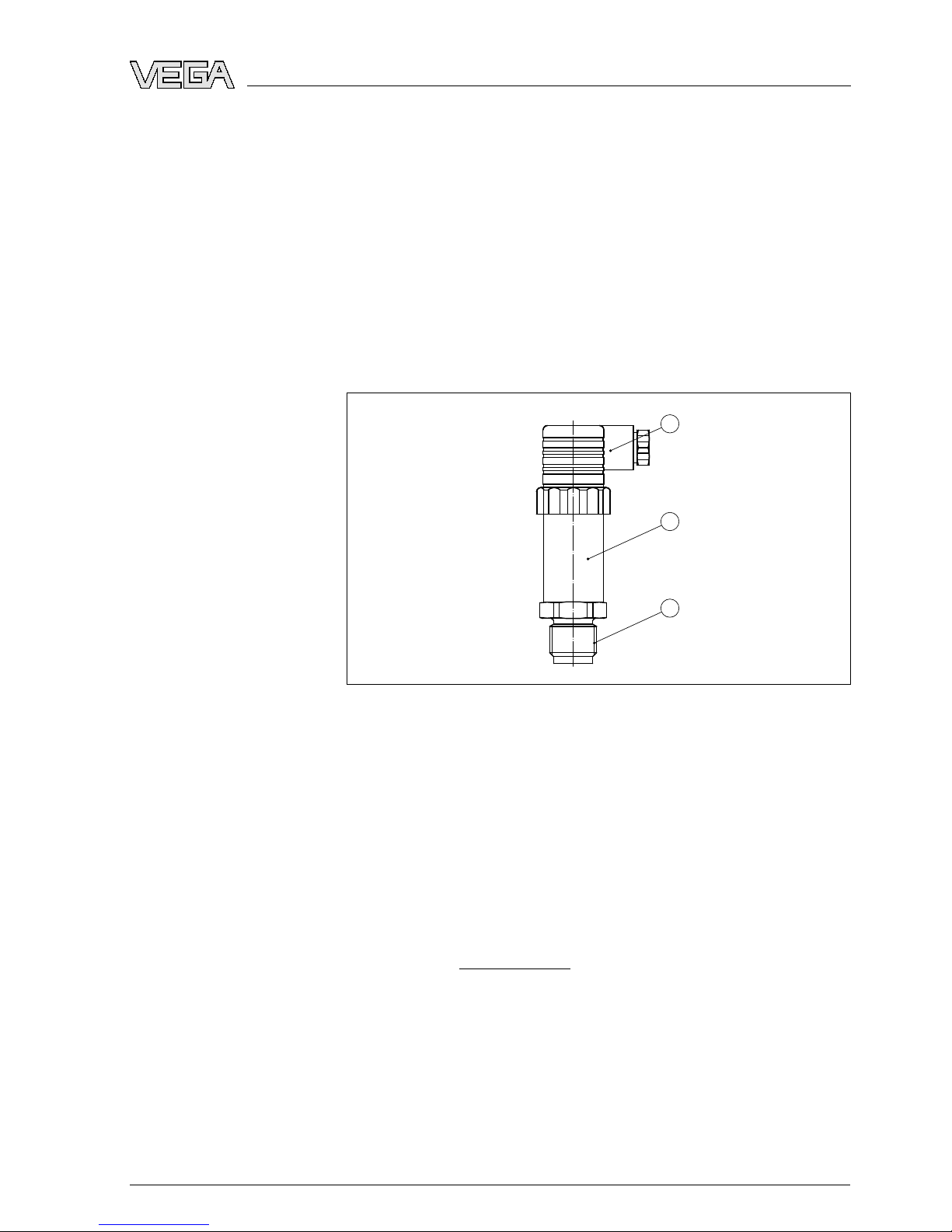
The process pressure acts on the sensor element via the stainless
steel diaphragm.The process pressure causes a resistance change
which is converted into a corresponding output signal and outputted as
measured value.1)
Two-wire electronics 4…20 mAfor power supply and measured
value transmission on the same cable.
3.3Operation
VEGABAR 17 has no adjustment options.However,two potentiom-
eters are integrated for the recalibration of zero and span.
3.4Packaging,transport and storage
Your instrument was protected by packaging during transport.Its
capacity to handle normal loads during transport is assured by a test
according to DIN EN 24180.
The packaging of standard instruments consists of environment-
friendly,recyclable cardboard.For special versions,PE foam or PE foil
is also used.Dispose of the packaging material via specialised
recycling companies.
Instruments for oxygen applications are sealed in PE foil and provided
with a label "Oxygen!Use no Oil".Remove this foil just before
mounting the instrument!See instruction under "Mounting".
Transport must be carried out under consideration of the notes on the
transport packaging.Nonobservance of these instructions can cause
damage to the device.
The delivery must be checked for completeness and possible transit
damage immediately at receipt.Ascertained transit damage or
concealed defects must be appropriately dealt with.
Up to the time of installation,the packages must be left closed and
stored according to the orientation and storage markings on the
outside.
1)Measuring ranges up to 16 bar:piezoresistive sensor element with internal
transmission liquid,with measuring ranges up to 25 bar:Strain gauge
(DMS)sensor element on the rear of the stainless steel diaphragm (dry).
Area of application
Functional principle
Voltage supply
Packaging
Transport
Transport inspection
Storage
8VEGABAR 17
3Product description
27636-EN-081029

Unless otherwise indicated,the packages must be stored only under
the following conditions:
lNot in the open
lDry and dust free
lNot exposed to corrosive media
lProtected against solar radiation
lAvoiding mechanical shock and vibration
lStorage and transport temperature see chapter "Supplement -
Technical data -Ambient conditions"
lRelative humidity 20 …85 %
Storage and transport
temperature
VEGABAR 17 9
3Product description
27636-EN-081029

4Mounting
4.1General instructions
Make sure that all parts of the instrument in contact with the measured
product,especially the sensor element,process seal and process
fitting,are suitable for the existing process conditions such as process
pressure,process temperature as well as the chemical properties of
the medium.
You can find the specifications in chapter "Technical data"in the or on
the type label.
Caution:
After removal of the diaphragm protective cover,the diaphragm must
not be pressed.
Danger:
Instruments in the version "Oil and grease free for oxygen"should be
unpacked just before mounting.After the protective cover of the
process fitting has been removed,the label "O₂"on the process fitting
is visible.Contamination by oil,grease and dirt should be avoided.
Danger of explosion!
4.2Mounting instructions
VEGABAR 17 functions in any installation position.It is mounted
according to the same directives as a manometer (DIN EN 839-2).
Information:
We recommend using lock fittings,measuring instrument holders and
siphons from our line of accessories.
4.3Mounting steps
For mounting VEGABAR 17,a welded socket is required.You can find
these components in the supplementary instructions manual "Welded
socket and seals".
For the following process fittings use the O-ring seal that belongs to
the respective instrument.
-or -
With the following process fittings,seal the thread with teflon,hemp or
a similar seal material:
lProcess fitting ½NPT
lProcess fitting ¼NPT
Suitability for process
conditions
Diaphragm pro-
tection
Oxygen applica-
tions
Mounting position
Welding the socket
Sealing/Screwing in
10 VEGABAR 17
4Mounting
27636-EN-081029

àScrew VEGABAR 17 into the welded socket.Tighten the hexagon
screw on the process fitting.Wrench size,see chapter "Dimen-
sions",torque see chapter "Technical data".
Fig.2:Installation of VEGABAR 17
VEGABAR 17 11
4Mounting
27636-EN-081029

5Connecting to power supply
5.1Preparing the connection
Always keep in mind the following safety instructions:
lConnect only in the complete absence of line voltage
lIf overvoltage surges are expected,overvoltage arresters should
be installed.
Tip:
We recommend VEGA overvoltage arrester ÜSB 62-36G.X.
In hazardous areas you should take note of the appropriate
regulations,conformity and type approval certificates of the sensors
and power supply units.
The supply voltage and the current signal are carried on the same two-
wire connection cable.
Provide a reliable separation between the supply circuit and the mains
circuits according to DIN VDE 0106 part 101.
VEGA power supply units VEGATRENN 149AEx,VEGASTAB 690,
VEGADIS 371 as well as all VEGAMETs meet this requirement.When
using one of these instruments,protection class III is ensured for
VEGABAR 17.
Bear in mind the following factors regarding supply voltage:
lOutput voltage of the power supply unit can be lower under
nominal load (with a sensor current of 20.5mAor 22 mAin case of
fault message)
lInfluence of additional instruments in the circuit (see load values in
chapter "Technical data")
The instrument is connected with standard two-wire cable without
screen.If electromagnetic interference is expected which is above the
test values of EN 61326 for industrial areas,screened cable should be
used.
Use cable with round cross-section.Acable outer diameter of 5…9mm
(0.2…0.35 in)ensures the seal effect of the cable gland.If you are
using cable with other diameter or cross-section,you have to
exchange the seal or use a suitable cable gland.
For the version with round plug connector M12 x1,the suitable
confectioned connection cable (article no.ASL.1S.) is available from
the line of VEGA accessory with 5m,10 m or 25 m length.
Note safety instructions
Take note of
safety instruc-
tions for Ex ap-
plications
Select power supply
Selecting connection
cable
12 VEGABAR 17
5Connecting to power supply
27636-EN-081029

Connect the cable screen on both ends to ground potential.
If potential equalisation currents are expected,the connection on the
processing side must be made via a ceramic capacitor (e.g.1nF,
1500 V). The low frequency potential equalisation currents are thus
suppressed,but the protective effect against high frequency interfer-
ence signals remains.
Take note of the corresponding installation regulations for Ex
applications.
5.2Connection procedure
Proceed as follows:
1Loosen the screw on the rear of the plug connector
2Remove the plug connector and seal from VEGABAR 17
3Remove the plug insert out of the plug housing
1
2
3
Fig.3:Loosen the plug insert
1Cable gland
2Plug insert
3Plug housing
4Remove approx.5cm of the cable mantle,strip approx.1cm
insulation from the individual wires
5Lead the cable through the cable gland into the plug housing
6Connect the wire ends to the screw terminals according to the
wiring plan
Cable screening and
grounding
Select connec-
tion cable for Ex
applications
Connection via angle
plug connector
VEGABAR 17 13
5Connecting to power supply
27636-EN-081029

2
3
1
4
Fig.4:Connection to the screw terminals
1Cable gland
2Plug housing
3Plug insert
4Plug seal
7Snap the plug insert into the plug housing and insert the sensor
seal
8Plug the plug insert with seal to VEGABAR 17 and tighten the
screw
The electrical connection is finished.
Proceed as follows:
1Loosen the screw in the cover of the plug connector
2Open the cover and remove it
3Press the plug insert downwards
4Loosen the screws of the strain relief and cable entry
Connection via angle
plug connector with
hinged cover
14 VEGABAR 17
5Connecting to power supply
27636-EN-081029

4
32
1
3
2
1
Fig.5:Loosen the plug insert
1Plug insert
2Strain relief
3Cable gland
4Plug housing
5Remove approx.5cm of the cable mantle,strip approx.1cm
insulation from the individual wires
6Lead the cable through the cable gland into the plug housing
7Connect the wire ends to the screw terminals according to the
wiring plan
1
5
2
3
4
Fig.6:Connection to the screw terminals
1Cable gland
2Cover
3Plug housing
4Plug insert
5Plug seal
8Snap the plug insert into the plug housing and insert the sensor
seal
VEGABAR 17 15
5Connecting to power supply
27636-EN-081029

Information:
Note the correct arrangement,see illustration
9Tighten the screws on the strain relief and cable entry
10 Hook in the cover and push onto the plug connection,tighten
cover screw
11 Plug the plug insert with seal to VEGABAR 17 and tighten the
screw
The electrical connection is finished.
5.3Wiring plan
1
2
3
+
-
1
Fig.7:Wiring plan,angle plug connector according to DIN 43650-A,top view to
VEGABAR 17
1Voltage supply and signal output
3
+
-
1
3
2
4
1
Fig.8:Wiring plan,round plug connector M12 x1,top view to VEGABAR 17
1Voltage supply and signal output
Angle plug connector
according to DIN 43650-
A
Round plug connector
M12 x1
16 VEGABAR 17
5Connecting to power supply
27636-EN-081029

1
2
3
Fig.9:Wiring plan cable outlet
1brown (+)power supply and signal output
2green (-) power supply and signal output
3blue =cable screen
321
–
+
–
+
4 5
1
2
Fig.10:Wiring plan,terminal housing
1To power supply or the processing system
2Control instrument (4…20 mAmeasurement)
Cable outlet
Terminal housing
VEGABAR 17 17
5Connecting to power supply
27636-EN-081029

6Set up
6.1Setup procedure
After mounting and electrical connection,VEGABAR 17 is ready for
operation.
VEGABAR 17 delivers a current of 4…20 mAaccording to the actual
process pressure.Further settings are not necessary.
6.2Recalibration
Zero and span can be readjusted via potentiometer.
Recommended recalibration cycle:1year.
Proceed as follows:
1In closed status,unscrew the handle ring and open the instrument
Fig.11:Open the instrument
2Adjust zero in unpressurized condition
3Set a span with a sufficiently precise reference pressure2)
4Check zero
2)At least 3-times as exact as the pressure transmitter.
Angled and round plug
connector,cable outlet
18 VEGABAR 17
6Set up
27636-EN-081029

Fig.12:Adjustment zero and span
Zzero
Sspan
5Close the instrument and tighten the handle ring
Proceed as follows:
1Screw on the housing cover in connected status
Fig.13:Adjustment zero and span
Zzero
Sspan
2Adjust zero in unpressurized condition
3Set a span with a sufficiently precise reference pressure3)
4Check zero
3)At least 3-times as exact as the pressure transmitter.
Terminal housing
VEGABAR 17 19
6Set up
27636-EN-081029

5Screw the housing cover on
20 VEGABAR 17
6Set up
27636-EN-081029
Other manuals for VEGABAR 17
3
Table of contents
Other Vega Measuring Instrument manuals

Vega
Vega VEGAMIP R61 User manual

Vega
Vega VEGASOURCE 31 Wiring diagram

Vega
Vega VEGACAP 65 User manual

Vega
Vega VEGAPULS 65 User manual

Vega
Vega PULS SR 68 User manual

Vega
Vega VEGAPULS WL 61 User manual

Vega
Vega VEGAPULS 66 enamel User manual

Vega
Vega VEGADIS 82 User manual

Vega
Vega VEGAFLEX 86 User manual

Vega
Vega DSGH User manual

Vega
Vega VEGASON 61 User manual

Vega
Vega VEGACAL 63 User manual

Vega
Vega WEIGHTRAC 31 User manual

Vega
Vega SHLG User manual

Vega
Vega VEGAPULS 63 User manual

Vega
Vega VEGACAP 67 User manual

Vega
Vega VEGAFLEX 80 Series Wiring diagram

Vega
Vega VEGACAL 64 User manual

Vega
Vega VEGAPULS 61 User manual

Vega
Vega MINITRAC 31 User manual