Vega VEGACAL 69 User manual

Operating Instructions
Capacitive double rod electrode for level
measurement
VEGACAL 69
Probus PA
Document ID: 31179

2
Contents
VEGACAL 69 • Probus PA
31179-EN-200929
Contents
1 About this document ............................................................................................................... 4
1.1 Function ........................................................................................................................... 4
1.2 Target group ..................................................................................................................... 4
1.3 Symbols used................................................................................................................... 4
2 For your safety ......................................................................................................................... 5
2.1 Authorised personnel ....................................................................................................... 5
2.2 Appropriate use................................................................................................................ 5
2.3 Warning about incorrect use............................................................................................. 5
2.4 General safety instructions............................................................................................... 5
2.5 EU conformity................................................................................................................... 5
2.6 NAMUR recommendations .............................................................................................. 6
2.7 Installation and operation in the USA and Canada ........................................................... 6
2.8 Safety instructions for Ex areas ........................................................................................ 6
2.9 Environmental instructions ............................................................................................... 6
3 Product description ................................................................................................................. 7
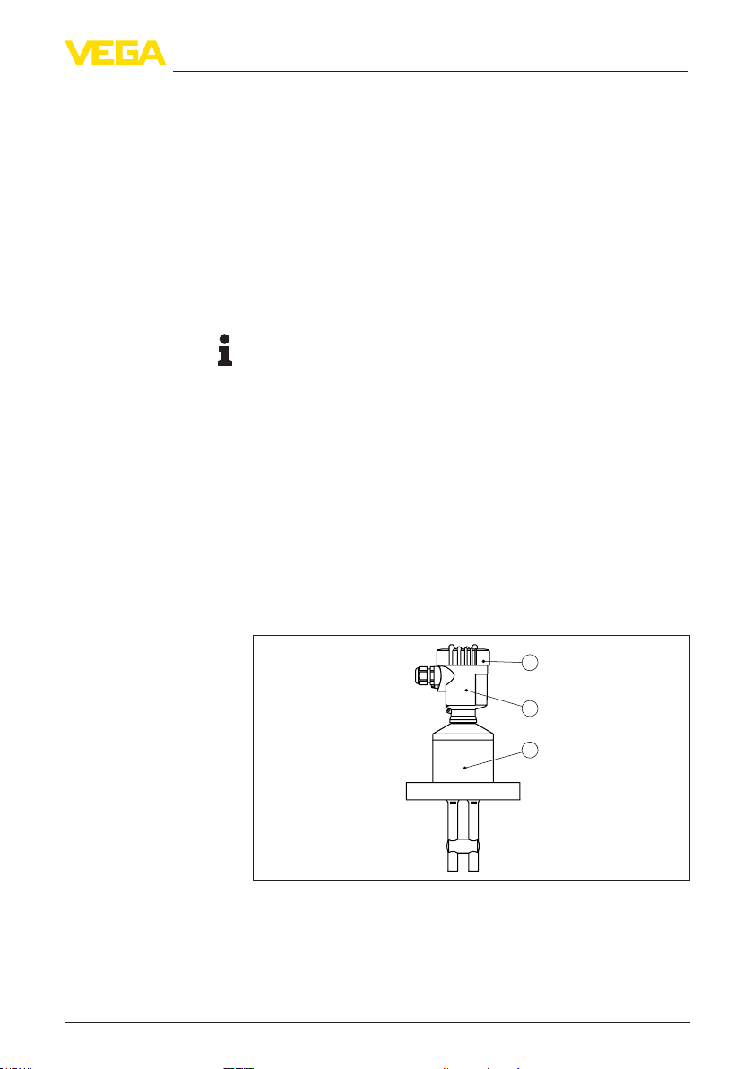
3.1 Conguration.................................................................................................................... 7
3.2 Principle of operation........................................................................................................ 9
3.3 Adjustment..................................................................................................................... 10
3.4 Packaging, transport and storage................................................................................... 10
3.5 Accessories.................................................................................................................... 10
4 Mounting................................................................................................................................. 13
4.1 General instructions ....................................................................................................... 13
4.2 Mounting instructions ..................................................................................................... 14
5 Connecting to power supply................................................................................................. 16
5.1 Preparing the connection ............................................................................................... 16
5.2 Connection procedure.................................................................................................... 17
5.3 Wiring plan, single chamber housing.............................................................................. 18
5.4 Wiring plan, double chamber housing ............................................................................ 19
5.5 Wiring plan, Ex-d double chamber housing.................................................................... 21
5.6 Wiring plan - version IP66/IP68, 1 bar ............................................................................ 22
6 Set up with the display and adjustment module PLICSCOM ............................................ 23
6.1 Short description ............................................................................................................ 23
6.2 Insert display and adjustment module............................................................................ 23
6.3 Adjustment system......................................................................................................... 24
6.4 Setup steps .................................................................................................................... 25
6.5 Menu schematic............................................................................................................. 34
6.6 Saving the parameterisation data................................................................................... 36
7 Set up with PACTware and other adjustment programs .................................................... 37
7.1 Connect the PC.............................................................................................................. 37
7.2 Parameter adjustment with PACTware............................................................................ 38
7.3 Parameter adjustment with AMS™ and PDM................................................................. 39
7.4 Saving the parameterisation data................................................................................... 39
8 Set up with smartphone/tablet/PC/notebook via Bluetooth.............................................. 40
8.1 Preparations................................................................................................................... 40
8.2 Connecting..................................................................................................................... 41

3
Contents
VEGACAL 69 • Probus PA
31179-EN-200929
8.3 Sensor parameter adjustment........................................................................................ 42
9 Maintenanceandfaultrectication...................................................................................... 43
9.1 Maintenance .................................................................................................................. 43
9.2 Rectify faults................................................................................................................... 43
9.3 Exchanging the electronics module................................................................................ 44
9.4 How to proceed if a repair is necessary.......................................................................... 45
10 Dismount................................................................................................................................. 46
10.1 Dismounting steps.......................................................................................................... 46
10.2 Disposal ......................................................................................................................... 46
11 Supplement ............................................................................................................................ 47
11.1 Technical data ................................................................................................................ 47
11.2 Device communication Probus PA................................................................................ 51
11.3 Dimensions .................................................................................................................... 55
11.4 Industrial property rights................................................................................................. 57
11.5 Trademark ...................................................................................................................... 57
Editing status: 2020-09-24

4
1 About this document
VEGACAL 69 • Probus PA
31179-EN-200929
1 About this document
1.1 Function
This operating instructions provides all the information you need for
mounting, connection and setup as well as important instructions for
maintenance, fault rectication, the exchange of parts and the safety
of the user. Please read this information before putting the instrument
into operation and keep this manual accessible in the immediate
vicinity of the device.
1.2 Target group
This operating instructions manual is directed to trained personnel.
The contents of this manual must be made available to the qualied
personnel and implemented.
1.3 Symbols used
Document ID
This symbol on the front page of this instruction refers to the Docu-
ment ID. By entering the Document ID on www.vega.com you will
reach the document download.
Information, tip, note
This symbol indicates helpful additional information.
Caution: If this warning is ignored, faults or malfunctions can result.
Warning: If this warning is ignored, injury to persons and/or serious
damage to the instrument can result.
Danger: If this warning is ignored, serious injury to persons and/or
destruction of the instrument can result.
Ex applications
This symbol indicates special instructions for Ex applications.
SIL applications
This symbol indicates instructions for functional safety which must be
taken into account particularly for safety-relevant applications.
• List
The dot set in front indicates a list with no implied sequence.
→ Action
This arrow indicates a single action.
1 Sequence of actions
Numbers set in front indicate successive steps in a procedure.
Battery disposal
This symbol indicates special information about the disposal of bat-
teries and accumulators.

5
2 For your safety
VEGACAL 69 • Probus PA
31179-EN-200929
2 For your safety
2.1 Authorised personnel
All operations described in this documentation must be carried out
only by trained, qualied personnel authorised by the plant operator.
During work on and with the device, the required personal protective
equipment must always be worn.
2.2 Appropriate use
VEGACAL 69 is a sensor for continuous level measurement.
You can nd detailed information about the area of application in
chapter " Product description".
Operational reliability is ensured only if the instrument is properly
used according to the specications in the operating instructions
manual as well as possible supplementary instructions.
2.3 Warning about incorrect use
Inappropriate or incorrect use of this product can give rise to applica-
tion-specic hazards, e.g. vessel overll through incorrect mounting
or adjustment. Damage to property and persons or environmental
contamination can result. Also, the protective characteristics of the
instrument can be impaired.
2.4 General safety instructions
This is a state-of-the-art instrument complying with all prevailing
regulations and directives. The instrument must only be operated in a
technically awless and reliable condition. The operator is responsi-
ble for the trouble-free operation of the instrument. When measuring
aggressive or corrosive media that can cause a dangerous situation
if the instrument malfunctions, the operator has to implement suitable
measures to make sure the instrument is functioning properly.
The safety instructions in this operating instructions manual, the na-
tional installation standards as well as the valid safety regulations and
accident prevention rules must be observed by the user.
For safety and warranty reasons, any invasive work on the device
beyond that described in the operating instructions manual may be
carried out only by personnel authorised by the manufacturer. Arbi-
trary conversions or modications are explicitly forbidden. For safety
reasons, only the accessory specied by the manufacturer must be
used.
To avoid any danger, the safety approval markings and safety tips on
the device must also be observed.
2.5 EU conformity
The device fulls the legal requirements of the applicable EU direc-
tives. By axing the CE marking, we conrm the conformity of the
instrument with these directives.
The EU conformity declaration can be found on our homepage.

6
2 For your safety
VEGACAL 69 • Probus PA
31179-EN-200929
2.6 NAMUR recommendations
NAMUR is the automation technology user association in the process
industry in Germany. The published NAMUR recommendations are
accepted as the standard in eld instrumentation.
The device fulls the requirements of the following NAMUR recom-
mendations:
• NE 21 – Electromagnetic compatibility of equipment
• NE 43 – Signal level for fault information from measuring transduc-
ers
• NE 53 – Compatibility of eld devices and display/adjustment
components
For further information see www.namur.de.
2.7 Installation and operation in the USA and
Canada
This information is only valid for USA and Canada. Hence the follow-
ing text is only available in the English language.
Installations in the US shall comply with the relevant requirements of
the National Electrical Code (ANSI/NFPA 70).
Installations in Canada shall comply with the relevant requirements of
the Canadian Electrical Code.
2.8 Safety instructions for Ex areas
For Ex applications, only devices with corresponding Ex approval may
be used. Observe the Ex-specic safety instructions. These are an
integral part of the operating instructions and are enclosed with every
device with Ex approval.
2.9 Environmental instructions
Protection of the environment is one of our most important duties.
That is why we have introduced an environment management system
with the goal of continuously improving company environmental pro-
tection. The environment management system is certied according
to DIN EN ISO 14001.
Please help us full this obligation by observing the environmental
instructions in this manual:
• Chapter " Packaging, transport and storage"
• Chapter " Disposal"

7
3 Product description
VEGACAL 69 • Probus PA
31179-EN-200929
3 Product description
3.1 Conguration
The scope of delivery encompasses:
• Level sensor VEGACAL 69
The further scope of delivery encompasses:
• Documentation
– Operating instructions VEGACAL 69
– Instructions for optional instrument features
– Ex-specic " Safety instructions" (with Ex versions)
– If necessary, further certicates
Information:
Optional instrument features are also described in this operating
instructions manual. The respective scope of delivery results from the
order specication.
This operating instructions manual applies to the following instrument
versions:
• Hardware from 1.0.0
• Software from 1.3.0
• Only for instrument versions without SIL qualication
The VEGACAL 69 consists of the components:
• Process tting with probe
• Housing with electronics
• Housing cover, optionally available with display and adjustment
module
1
2
3
Fig. 1: VEGACAL 69 - double rod probe with plastic housing
1 Housing lid with integrated display and adjustment module (optional)
2 Housing with electronics
3 Processtting
Scope of delivery
Scope of this operating
instructions
Constituent parts

8
3 Product description
VEGACAL 69 • Probus PA
31179-EN-200929
The type label contains the most important data for identication and
use of the instrument:
2
1
11
13
12
14
15
10
9
3
6
4
5
7
8
Fig. 2: Layout of the type label (example)
1 Instrument type
2 Product code
3 Approvals
4 Process and ambient temperature, process pressure
5 Power supply and signal output, electronics
6 Protection rating
7 Probe length
8 Order number
9 Serial number of the instrument
10 Material wetted parts
11 Symbol of the device protection class
12 Reminder to observe the instrument documentation
13 ID numbers, instrument documentation
14 NotiedauthorityforCEmarking
15 Approval directives
With the serial number, you can access the delivery data of the instru-
ment via " www.vega.com", " Search". You can nd the serial number
on the inside of the instrument as well as on the type label on the
outside.
The type label contains the serial number of the instrument. With it
you can nd the following instrument data on our homepage:
• Product code (HTML)
• Delivery date (HTML)
• Order-specic instrument features (HTML)
• Operating instructions and quick setup guide at the time of ship-
ment (PDF)
• Order-specic sensor data for an electronics exchange (XML)
• Test certicate (PDF) - optional
Move to " www.vega.com" and enter in the search eld the serial
number of your instrument.
Alternatively, you can access the data via your smartphone:
• Download the VEGA Tools app from the " Apple App Store" or the
" Google Play Store"
• Scan the DataMatrix code on the type label of the instrument or
• Enter the serial number manually in the app
Type label
Serial number - Instru-
ment search

9
3 Product description
VEGACAL 69 • Probus PA
31179-EN-200929
3.2 Principle of operation
VEGACAL 69 is a level sensor for continuous level measurement of
liquids in non-conductive vessels or of corrosive liquids.
The double rod probe is fully insulated and highly resistant.
Probes and measured product form an electrical capacitor. The
capacitance is inuenced by three main factors.
1
2
3
Fig. 3: Functional principle - Plate capacitor
1 Distance between the electrode surfaces
2 Size of the electrode surfaces
3 Type of dielectric between the electrodes
The two probes are the capacitor plates. The measured product is
the dielectric. Due to the higher dielectric constant of the product
compared to air, the capacitance increases as the material gradually
covers the probe.
The capacitance as well as the resistance change are converted by
the electronics module into a level-proportional signal.
Power supply via the Probus DP/PA segment coupler or VEGALOG
571 EP cards. A two-wire cable according to Probus specication
serves as carrier of both power and digital data transmission for
multiple sensors. The instrument prole of VEGACAL 69 corresponds
to prole specication version 3.0.
The backlight of the display and adjustment module is powered by the
sensor. Prerequisite is a certain level of operating voltage.
The data for power supply are specied in chapter " Technical data".
The optional heating requires its own operating voltage. You can nd
further details in the supplementary instructions manual " Heating for
display and adjustment module".
This function is generally not available for approved instruments.
The GSD (instrument master les) and bitmap les necessary for
planning your Probus-DP-(PA) communication network are available
from the download section on the VEGA homepage www.vega.com.
There you can also nd the appropriate certicates. In a PDM envi-
ronment, an EDD (Electronic Device Description) is also required
to enable the full range of sensor functions (also available as a
Application area
Functional principle
Power supply and bus
communication
GSD/EDD

10
3 Product description
VEGACAL 69 • Probus PA
31179-EN-200929
download).A CD with the appropriate les can be ordered via e-mail
under info@de.vega.com or by phone from one of the VEGA agencies
under the order number "DRIVER.S".
3.3 Adjustment
The instrument can be adjusted with the following adjustment media:
• With the display and adjustment module
• with the suitable VEGA DTM in conjunction with an adjustment
software according to the FDT/DTM standard, e.g. PACTware and
PC
• with the adjustment program PDM
3.4 Packaging, transport and storage
Your instrument was protected by packaging during transport. Its
capacity to handle normal loads during transport is assured by a test
based on ISO 4180.
The packaging of standard instruments consists of environment-
friendly, recyclable cardboard. For special versions, PE foam or PE
foil is also used. Dispose of the packaging material via specialised
recycling companies.
Transport must be carried out in due consideration of the notes on the
transport packaging. Nonobservance of these instructions can cause
damage to the device.
The delivery must be checked for completeness and possible transit
damage immediately at receipt. Ascertained transit damage or con-
cealed defects must be appropriately dealt with.
Up to the time of installation, the packages must be left closed and
stored according to the orientation and storage markings on the
outside.
Unless otherwise indicated, the packages must be stored only under
the following conditions:
• Not in the open
• Dry and dust free
• Not exposed to corrosive media
• Protected against solar radiation
• Avoiding mechanical shock and vibration
• Storage and transport temperature see chapter " Supplement -
Technical data - Ambient conditions"
• Relative humidity 20 … 85 %
With instrument weights of more than 18 kg (39.68 lbs) suitable and
approved equipment must be used for lifting and carrying.
3.5 Accessories
The instructions for the listed accessories can be found in the down-
load area on our homepage.
Packaging
Transport
Transport inspection
Storage
Storage and transport
temperature
Lifting and carrying

11
3 Product description
VEGACAL 69 • Probus PA
31179-EN-200929
The display and adjustment module is used for measured value indi-
cation, adjustment and diagnosis.
The integrated Bluetooth module (optional) enables wireless adjust-
ment via standard adjustment devices.
The interface adapter VEGACONNECT enables the connection of
communication-capable instruments to the USB interface of a PC.
The VEGADIS 81 is an external display and adjustment unit for VEGA
plics®sensors.
VEGADIS 82 is suitable for measured value indication and adjustment
of sensors with HART protocol. It is looped into the 4 … 20 mA/HART
signal cable.
The PLICSMOBILE T81 is an external GSM/GPRS/UMTS radio unit
for transmission of measured values and for remote parameter adjust-
ment of HART sensors.
If the standard sensor housing is too big or in case of strong vibra-
tions, an external housing can be used.
Then the sensor housing is made of stainless steel. The electronics is
located in the external housing which can be mounted in a distance of
up to 10 m (32.8 ft) to the sensor by using a connection cable.
Three dierent external sensor housings are available.
3
A
1
2
Fig. 4: External housing
A Instrument housing
1 Sensor housing, stainless steel (316L), IP68 (10 bar)
2 Sensor housing, stainless steel (316L), IP67
3 Sensor housing, stainless steel (316L), BNC plug IP54
The protective cover protects the sensor housing against soiling and
intense heat from solar radiation.
PLICSCOM
VEGACONNECT
VEGADIS 81
VEGADIS 82
PLICSMOBILE T81
External housing
Protective cover

12
3 Product description
VEGACAL 69 • Probus PA
31179-EN-200929
Screwed anges are available in dierent versions according to the
following standards: DIN 2501, EN 1092-1, BS 10, ASME B 16.5,
JIS B 2210-1984, GOST 12821-80.
Flanges

13
4 Mounting
VEGACAL 69 • Probus PA
31179-EN-200929
4 Mounting
4.1 General instructions
Note:
For safety reasons, the instrument must only be operated within the
permissible process conditions. You can nd detailed information on
the process conditions in chapter " Technical data" of the operating
instructions or on the type label.
Hence make sure before mounting that all parts of the instrument ex-
posed to the process are suitable for the existing process conditions.
These are mainly:
• Active measuring component
• Process tting
• Process seal
Process conditions in particular are:
• Process pressure
• Process temperature
• Chemical properties of the medium
• Abrasion and mechanical inuences
Select an installation position you can easily reach for mounting and
connecting as well as later retrotting of a display and adjustment
module. The housing can be rotated by 330° without the use of any
tools. You can also install the display and adjustment module in four
dierent positions (each displaced by 90°).
Devices with threaded tting are screwed into the process tting with
a suitable wrench via the hexagon.
See chapter " Dimensions" for wrench size.
Warning:
The housing or the electrical connection may not be used for screw-
ing in! Depending on the device version, tightening can cause dam-
age, e. g. to the rotation mechanism of the housing.
Before beginning the welding work, remove the electronics module
from the sensor. By doing this, you avoid damage to the electronics
through inductive coupling.
Ground the probe before welding directly on the rod or cable.
Use the recommended cables (see chapter " Connecting to power
supply") and tighten the cable gland.
You can give your instrument additional protection against moisture
penetration by leading the connection cable downward in front of the
cable gland. Rain and condensation water can thus drain o. This
applies mainly to outdoor mounting as well as installation in areas
where high humidity is expected (e.g. through cleaning processes) or
on cooled or heated vessels.
Process conditions
Installation position
Screwing in
Welding work
Protection against mois-
ture

14
4 Mounting
VEGACAL 69 • Probus PA
31179-EN-200929
To maintain the housing protection, make sure that the housing lid is
closed during operation and locked, if necessary.
Fig. 5: Measures against moisture ingress
The process tting must be sealed if there is gauge or low pressure
in the vessel. Before use, check if the sealing material is resistant
against the measured product and the process temperature.
The max. permissible pressure is specied in chapter " Technical
data" or on the type label of the sensor.
Metric threads
In the case of instrument housings with metric thread, the cable
glands are screwed in at the factory. They are sealed with plastic
plugs as transport protection.
You have to remove these plugs before electrical connection.
NPT thread
In the case of instrument housings with self-sealing NPT threads, it is
not possible to have the cable entries screwed in at the factory. The
free openings for the cable glands are therefore covered with red dust
protection caps as transport protection.
Prior to setup you have to replace these protective caps with ap-
proved cable glands or close the openings with suitable blind plugs.
4.2 Mounting instructions
If the instrument is mounted in the lling stream, unwanted false
measurement signals can be generated. For this reason, mount the
instrument at a position in the vessel where no disturbances, e.g. from
lling openings, agitators, etc., can occur.
This applies particularly to instrument versions with a longer probe.
Pressure/Vacuum
Cable entries - NPT
thread
Cable glands
Inowingmedium

15
4 Mounting
VEGACAL 69 • Probus PA
31179-EN-200929
Fig.6:Inowingmedium

16
5 Connecting to power supply
VEGACAL 69 • Probus PA
31179-EN-200929
5 Connecting to power supply
5.1 Preparing the connection
Always keep in mind the following safety instructions:
• Carry out electrical connection by trained, qualied personnel
authorised by the plant operator
• If overvoltage surges are expected, overvoltage arresters should
be installed
Warning:
Only connect or disconnect in de-energized state.
The voltage supply is provided by a Probus DP /PA segment coupler.
The voltage supply range can dier depending on the instrument
version. You can nd the data for voltage supply in chapter "Technical
data".
Connection is made with screened cable according to the Probus
specication. Power supply and digital bus signal are carried over the
same two-wire connection cable.
Use cable with round cross section for instruments with housing and
cable gland. To ensure the seal eect of the cable gland (IP protection
rating), nd out which cable outer diameter the cable gland is suitable
for.
Use a cable gland tting the cable diameter.
Make sure that the entire installation is carried out according to the
Probus specication. In particular, make sure that the bus is termi-
nated with suitable terminating resistors.
You can nd detailed information of the cable specication, installa-
tion and topology in the "ProbusPA-UserandInstallationGuide-
line" on www.probus.com.
Metric threads
In the case of instrument housings with metric thread, the cable
glands are screwed in at the factory. They are sealed with plastic
plugs as transport protection.
Note:
You have to remove these plugs before electrical connection.
NPT thread
In the case of instrument housings with self-sealing NPT threads, it is
not possible to have the cable entries screwed in at the factory. The
free openings for the cable glands are therefore covered with red dust
protection caps as transport protection.
Note:
Prior to setup you have to replace these protective caps with ap-
proved cable glands or close the openings with suitable blind plugs.
Safety instructions
Voltage supply
Connection cable
Cable glands

17
5 Connecting to power supply
VEGACAL 69 • Probus PA
31179-EN-200929
On plastic housings, the NPT cable gland or the Conduit steel tube
must be screwed into the threaded insert without grease.
Max. torque for all housings, see chapter " Technical data".
Make sure that the cable screen and grounding are carried out ac-
cording to Fieldbus specication. We recommend to connect the
cable screening to ground potential on both ends.
In systems with potential equalisation, connect the cable screening
directly to ground potential at the power supply unit, in the connection
box and at the sensor. The screen in the sensor must be connected
directly to the internal ground terminal. The ground terminal outside
on the housing must be connected to the potential equalisation (low
impedance).
5.2 Connection procedure
Proceed as follows:
1. Unscrew the housing lid
2. If a display and adjustment module is installed, remove it by turn-
ing it to the left
3. Loosen compression nut of the cable gland and remove blind
plug
4. Remove approx. 10 cm (4 in) of the cable mantle, strip approx.
1 cm (0.4 in) of insulation from the ends of the individual wires
5. Insert the cable into the sensor through the cable entry
6. Lift the opening levers of the terminals with a screwdriver (see
following illustration)
7. Insert the wire ends into the open terminals according to the wir-
ing plan
Fig. 7: Connection steps 6 and 7
8. Press down the opening levers of the terminals, you will hear the
terminal spring closing
9. Check the hold of the wires in the terminals by lightly pulling on
them
10. Connect the shielding to the internal ground terminal, connect the
external ground terminal to potential equalisation
Cable screening and
grounding

18
5 Connecting to power supply
VEGACAL 69 • Probus PA
31179-EN-200929
11. Tighten the compression nut of the cable entry gland. The seal
ring must completely encircle the cable
12. Screw the housing lid back on
The electrical connection is nished.
5.3 Wiring plan, single chamber housing
The following illustrations apply to the non-Ex as well as to the Ex-ia
version.
1 2
4
3
5
5
55
Fig. 8: Material versions, single chamber housing
1 Plastic
2 Aluminium
3 Stainless steel (precision casting)
4 Stainless steel (electro-polished)
5 Filter element for air pressure compensation of all material versions. Blind
plug with version IP66/IP68, 1 bar for Aluminium and stainless steel
Housing overview

19
5 Connecting to power supply
VEGACAL 69 • Probus PA
31179-EN-200929
I²C
Display
12 5678
3
4
1
2
Fig. 9: Electronics and connection compartment - single chamber housing
1 Plug connector for VEGACONNECT (I²C interface)
2 Spring-loaded terminals for connection of the external indication VEGADIS
81
3 Ground terminal for connection of the cable screening
4 Spring-loaded terminals for voltage supply
I2C
Display
1
12 5678
Fig. 10: Wiring plan - single chamber housing
1 Voltage supply, signal output
5.4 Wiring plan, double chamber housing
The following illustrations apply to the non-Ex as well as to the Ex-ia
version.
Electronics and connec-
tion compartment
Wiring plan

20
5 Connecting to power supply
VEGACAL 69 • Probus PA
31179-EN-200929
1 2 3
45
Fig. 11: Double chamber housing
1 Housing cover - connection compartment
2 Blind plug or plug M12 x 1 for VEGADIS 81 (optional)
3 Housing cover - electronics compartment
4 Filter element for air pressure compensation
5 Cable gland
1
32
Display
12 5678
I2C
Fig. 12: Electronics compartment - double chamber housing
1 Plug connector for VEGACONNECT (I²C interface)
2 Internal connection cable to the connection compartment
3 Terminals for VEGADIS 81
1
2
3
Display
12
I2C
Fig. 13: Connection compartment - double chamber housing
1 Spring-loaded terminals for voltage supply
2 Plug connector for service (I²C interface)
3 Ground terminal for connection of the cable screening
Housing overview
Electronics compartment
Connection compartment
Other manuals for VEGACAL 69
1
Table of contents
Other Vega Measuring Instrument manuals

Vega
Vega VEGAFLEX 82 User manual

Vega
Vega VEGAMIP U61 User manual

Vega
Vega VEGAVIB 62 Installation instructions

Vega
Vega VEGAPULS WL 61 User manual

Vega
Vega VEGABAR 38 User manual

Vega
Vega VEGASON 62 User manual

Vega
Vega VEGACAP 63 Wiring diagram

Vega
Vega VEGABAR 17 User manual

Vega
Vega VEGAFLEX 81 User manual

Vega
Vega VEGACAP 66 User manual

Vega
Vega VEGASWING 51 User manual

Vega
Vega VEGACAL 66 User manual

Vega
Vega VEGAPULS 61 User manual

Vega
Vega VEGAFLEX 86 User manual

Vega
Vega VEGACAL 67 User manual

Vega
Vega VEGABAR 54 User manual

Vega
Vega VEGABAR 66 User manual

Vega
Vega VEGAPULS 63 User manual

Vega
Vega VEGAPULS 64 User manual

Vega
Vega VEGAPULS 69 User manual