2
Contents
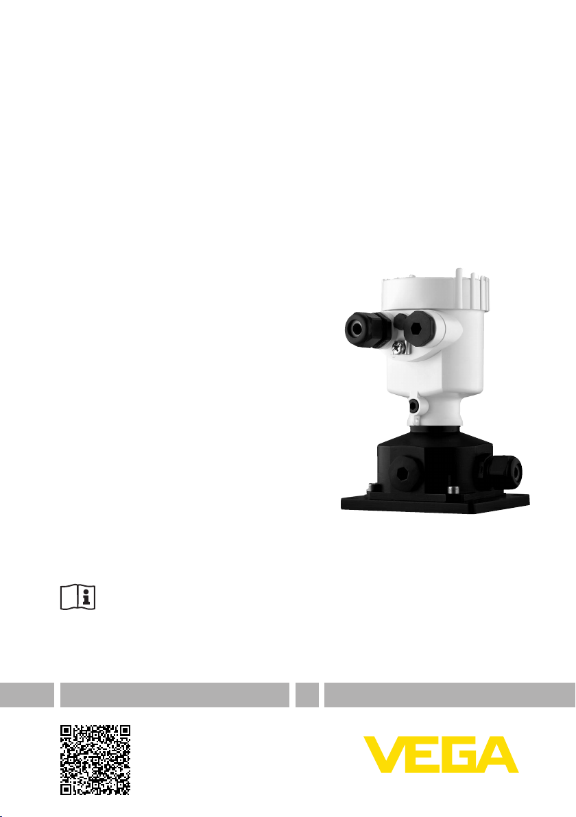
External housing • VEGAWAVE
32357-EN-140801
Contents
1 About this document
1.1 Function ........................................................................................................................... 3
1.2 Target group ..................................................................................................................... 3
1.3 Symbols used................................................................................................................... 3
2 For your safety
2.1 Authorised personnel ....................................................................................................... 4
2.2 Appropriate use................................................................................................................ 4
2.3 Safety instructions for Ex areas ........................................................................................ 4
2.4 Environmental instructions ............................................................................................... 4
3 Product description
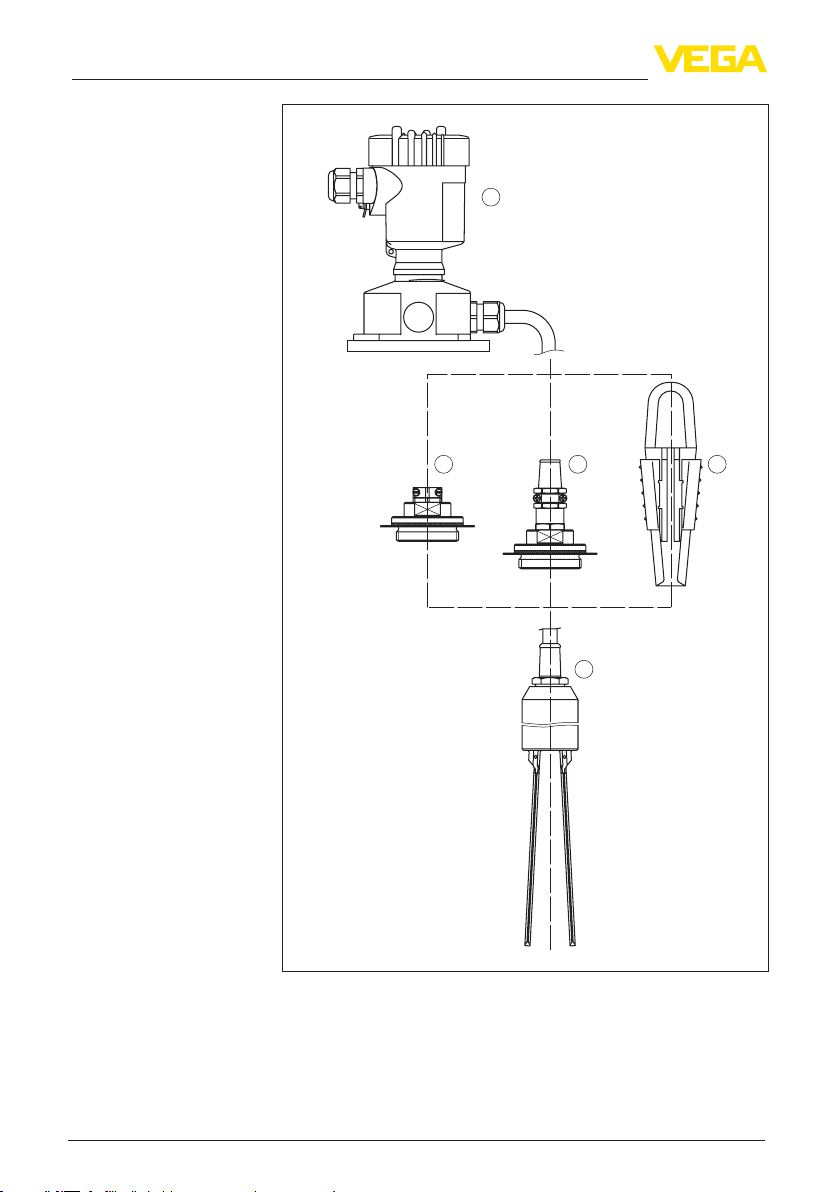
3.1 Conguration.................................................................................................................... 5
3.2 Principle of operation........................................................................................................ 8
3.3 Storage and transport....................................................................................................... 8
4 Mounting
4.1 General instructions ......................................................................................................... 9
4.2 Mounting preparations ..................................................................................................... 9
4.3 Mounting steps................................................................................................................. 9
4.4 Mounting - external housing (instrument housing).......................................................... 10
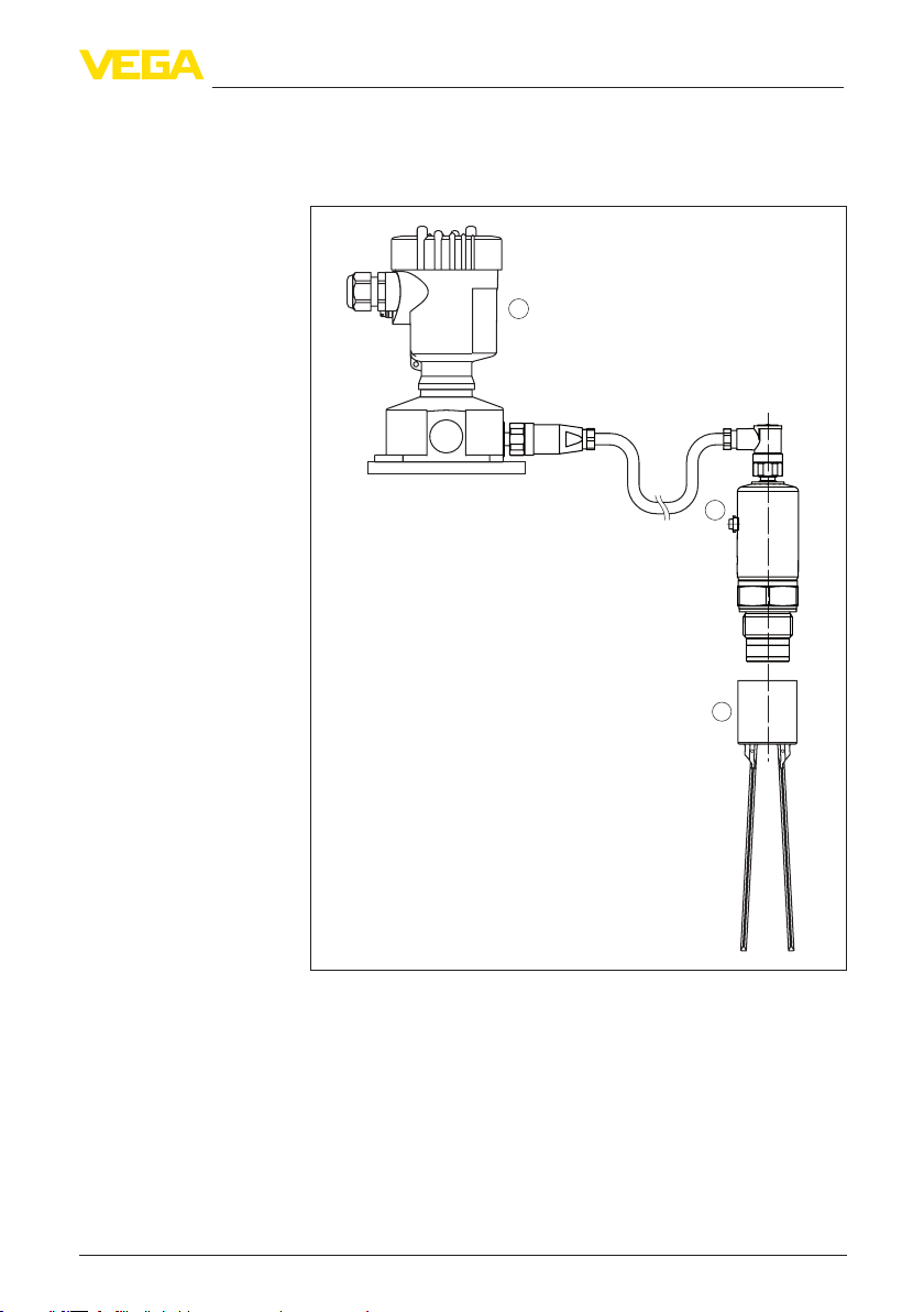
5 Connect the sensor to the external housing
5.1 Preparing the connection ............................................................................................... 11
5.2 Connection procedure.................................................................................................... 11
6 Setup
6.1 Setup.............................................................................................................................. 13
7 Maintenance
7.1 Instrument repair ............................................................................................................ 14
8 Dismount
8.1 Dismounting steps.......................................................................................................... 15
8.2 Disposal ......................................................................................................................... 15
9 Supplement
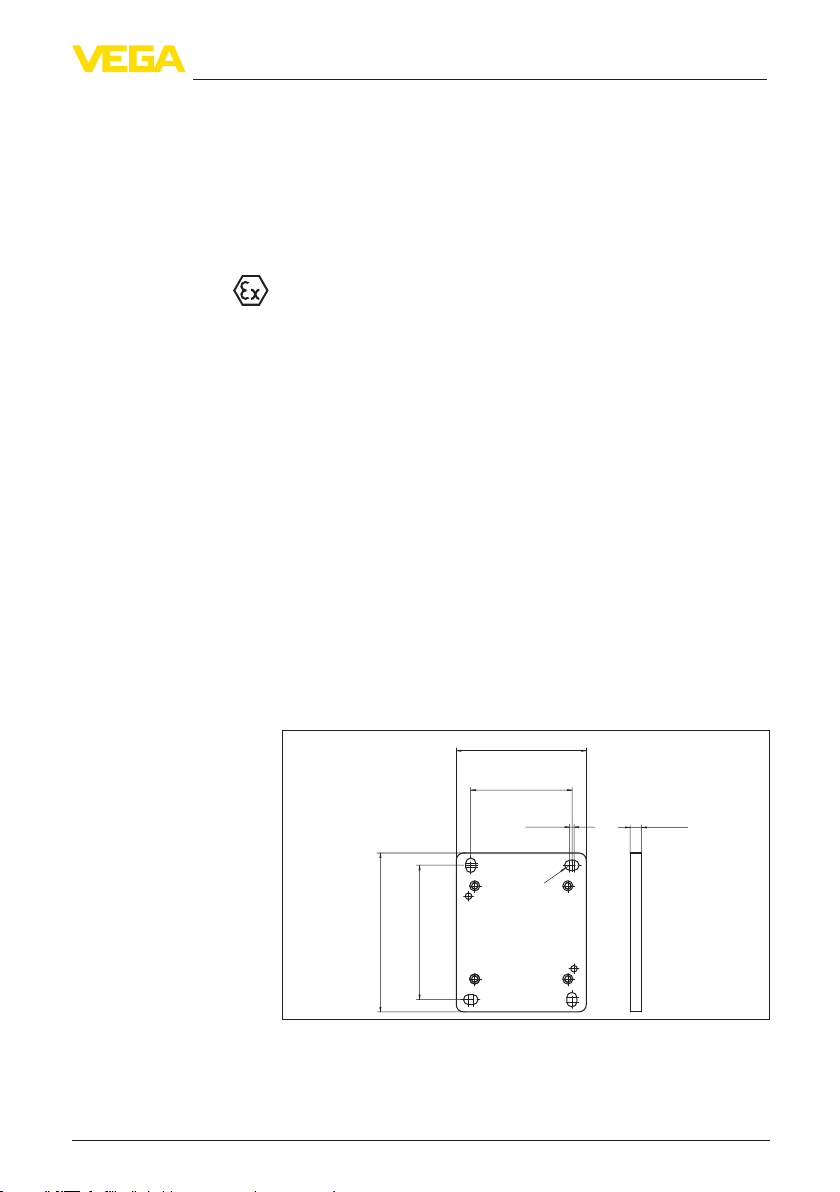
9.1 Technical data ................................................................................................................ 16
9.2 Dimensions .................................................................................................................... 17