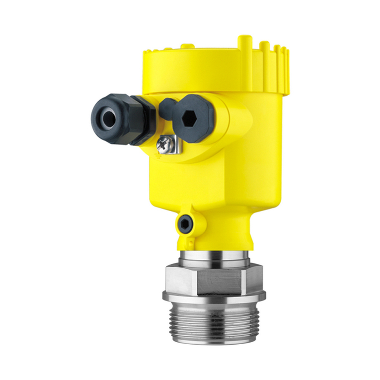
Vega VEGAPULS WL 61 User manual

Operating Instructions
Radar sensor for continuous level
measurement of water and wastewater
VEGAPULS WL 61
Probus PA
Document ID: 38062

2
Contents
VEGAPULS WL 61 • Probus PA
38062-EN-140801
Contents
1 About this document
1.1 Function ........................................................................................................................... 4
1.2 Target group ..................................................................................................................... 4
1.3 Symbols used................................................................................................................... 4
2 For your safety
2.1 Authorised personnel ....................................................................................................... 5
2.2 Appropriate use................................................................................................................ 5
2.3 Warning about incorrect use............................................................................................. 5
2.4 General safety instructions............................................................................................... 5
2.5 CE conformity................................................................................................................... 6
2.6 NAMUR recommendations .............................................................................................. 6
2.7 Radio license for Europe .................................................................................................. 6
2.8 Radio license for USA/Canada......................................................................................... 7
2.9 Environmental instructions ............................................................................................... 7
3 Product description
3.1 Conguration.................................................................................................................... 8
3.2 Principle of operation........................................................................................................ 9
3.3 Packaging, transport and storage..................................................................................... 9
4 Mounting
4.1 General instructions ....................................................................................................... 11
4.2 Mounting versions .......................................................................................................... 11
4.3 Mounting preparations, mounting strap .......................................................................... 14
4.4 Mounting instructions ..................................................................................................... 14
5 Connecting to power supply
5.1 Preparing the connection ............................................................................................... 20
5.2 Wiring plan ..................................................................................................................... 20
5.3 Switch-on phase............................................................................................................. 21
6 Setup
6.1 DD adjustment programs ............................................................................................... 22
6.2 Adjustment..................................................................................................................... 22
7 Diagnosis, asset management and service
7.1 Maintenance .................................................................................................................. 23
7.2 Measured value and event memory ............................................................................... 23
7.3 Asset Management function........................................................................................... 24
7.4 Rectify faults................................................................................................................... 28
7.5 How to proceed if a repair is needed .............................................................................. 31
8 Dismount
8.1 Dismounting steps.......................................................................................................... 32
8.2 Disposal ......................................................................................................................... 32
9 Supplement
9.1 Technical data ................................................................................................................ 33
9.2 Radio astronomy stations............................................................................................... 37
9.3 Communication Probus PA........................................................................................... 38
9.4 Dimensions .................................................................................................................... 42
3
Contents
VEGAPULS WL 61 • Probus PA
38062-EN-140801
Safety instructions for Ex areas
Please note the Ex-specic safety information for installation and op-
eration in Ex areas. These safety instructions are part of the operating
instructions manual and come with the Ex-approved instruments.
Editing status:2014-05-05

4
1 About this document
VEGAPULS WL 61 • Probus PA
38062-EN-140801
1 About this document
1.1 Function
This operating instructions manual provides all the information you
need for mounting, connection and setup as well as important instruc-
tions for maintenance and fault rectication. Please read this informa-
tion before putting the instrument into operation and keep this manual
accessible in the immediate vicinity of the device.
1.2 Target group
This operating instructions manual is directed to trained specialist
personnel. The contents of this manual should be made available to
these personnel and put into practice by them.
1.3 Symbols used
Information, tip, note
This symbol indicates helpful additional information.
Caution: If this warning is ignored, faults or malfunctions can result.
Warning: If this warning is ignored, injury to persons and/or serious
damage to the instrument can result.
Danger: If this warning is ignored, serious injury to persons and/or
destruction of the instrument can result.
Ex applications
This symbol indicates special instructions for Ex applications.
•List
The dot set in front indicates a list with no implied sequence.
→ Action
This arrow indicates a single action.
1 Sequence of actions
Numbers set in front indicate successive steps in a procedure.
Battery disposal
This symbol indicates special information about the disposal of bat-
teries and accumulators.

5
2 For your safety
VEGAPULS WL 61 • Probus PA
38062-EN-140801
2 For your safety
2.1 Authorised personnel
All operations described in this operating instructions manual must
be carried out only by trained specialist personnel authorised by the
plant operator.
During work on and with the device the required personal protective
equipment must always be worn.
2.2 Appropriate use
VEGAPULS WL 61 is a sensor for continuous level measurement.
You can nd detailed information about the area of application in
chapter "Product description".
Operational reliability is ensured only if the instrument is properly
used according to the specications in the operating instructions
manual as well as possible supplementary instructions.
2.3 Warning about incorrect use
Inappropriate or incorrect use of the instrument can give rise to
application-specic hazards, e.g. vessel overll or damage to system
components through incorrect mounting or adjustment.
2.4 General safety instructions
This is a state-of-the-art instrument complying with all prevailing
regulations and guidelines. The instrument must only be operated in a
technically awless and reliable condition. The operator is responsible
for the trouble-free operation of the instrument.
During the entire duration of use, the user is obliged to determine the
compliance of the necessary occupational safety measures with the
current valid rules and regulations and also take note of new regula-
tions.
The safety instructions in this operating instructions manual, the na-
tional installation standards as well as the valid safety regulations and
accident prevention rules must be observed by the user.
For safety and warranty reasons, any invasive work on the device
beyond that described in the operating instructions manual may be
carried out only by personnel authorised by the manufacturer. Arbi-
trary conversions or modications are explicitly forbidden.
The safety approval markings and safety tips on the device must also
be observed.
Depending on the instrument version, the emitting frequencies are in
the C or K band range. The low emitting frequencies are far below the
internationally approved limit values. When used correctly, there is no
danger to health.

6
2 For your safety
VEGAPULS WL 61 • Probus PA
38062-EN-140801
2.5 CE conformity
The device fullls the legal requirements of the applicable EC guide-
lines. By axing the CE marking, we conrm successful testing of the
product.
You can nd the CE Certicate of Conformity in the download section
of our homepage.
2.6 NAMUR recommendations
NAMUR is the automation technology user association in the process
industry in Germany. The published NAMUR recommendations are
accepted as the standard in eld instrumentation.
The device fullls the requirements of the following NAMUR recom-
mendations:
•NE 43 – Signal level for malfunction information from measuring
transducers
•NE 53 – Compatibility of eld devices and display/adjustment
components
•NE 107 - Self-monitoring and diagnosis of eld devices
For further information see www.namur.de.
2.7 Radio license for Europe
The instrument meets the LPR (Level Probing Radar) radio standard
EN 302729-1/2.
It is approved for unrestricted use inside and outside of closed ves-
sels in countries of the EU and EFTA that have implemented this
standard:
Austria, Belgium, Bulgaria, Germany, Denmark, Estonia, France,
Greece, Great Britain, Ireland, Island, Italy, Liechtenstein, Lithuania,
Latvia, Luxembourg, Malta, Netherlands, Norway, Poland, Portugal,
Romania, Sweden, Switzerland, Slovakia, Slovenia, Spain, Czech
Republik and Cyprus.
Not included in the CE conrmity declaration are the countries Fin-
land and Hungary implementing this radio standard at a later date.
For operation outside of closed vessels, the following conditions must
be fullled:
•The installation must be carried out by trained qualied personnel
•The instrument must be stationary mounted and the antenna
directed vertically downward
•The mounting location must be at least 4 km away from the radio
astronomy stations, unless special permission was granted by the
responsible national approval authority
•When installed within 4 to 40 km of a radio astronomy station,
the instrument must not be mounted higher than 15 m above the
ground.
You can nd a list with the respective radio astronomy stations in
chapter "Supplement".

7
2 For your safety
VEGAPULS WL 61 • Probus PA
38062-EN-140801
2.8 Radio license for USA/Canada
The instrument is in conformity with part 15 of the FCC regulations.
Operation is subject to the following two conditions:
•this device may not cause harmful interference, and
•this device must accept any interference received, including inter-
ference that may cause undesired operation.
•the antenna must be directed vertically downward
FCC requirements limit this device to be used only in a xed instal-
lation, never in a portable installation or in installations that are in
motion (i.e. cement trucks, etc.).
Changes or modications not expressly approved by the manufac-
turer could void the user’s authority to operate the equipment.
This device complies with Industry Canada license-exempt RSS
standard(s). Operation is subject to the following two conditions:
•this device may not cause interference, and
•this device must accept any interference, including interference
that may cause undesired operation of the device
Le présent appareil est conforme aux CNR d'Industrie Canada ap-
plicables aux appareils radio exempts de licence. L'exploitation est
autorisée aux deux conditions suivantes:
•l'appareil ne doit pas produire de brouillage , et
•l'utilisateur de l'appareil doit accepter tout brouillage radioélect-
rique subi, même si le brouillage est susceptible d'en compromet-
tre le fonctionnement
2.9 Environmental instructions
Protection of the environment is one of our most important duties.
That is why we have introduced an environment management system
with the goal of continuously improving company environmental pro-
tection. The environment management system is certied according
to DIN EN ISO 14001.
Please help us fulll this obligation by observing the environmental
instructions in this manual:
•Chapter "Packaging, transport and storage"
•Chapter "Disposal"

8
3 Product description
VEGAPULS WL 61 • Probus PA
38062-EN-140801
3 Product description
3.1 Conguration
The type label contains the most important data for identication and
use of the instrument:
2
1
14
15
16
17
13
12
11
5
3
6
4
7
8
9
10
Fig. 1: Layout of the type label (example)
1 Instrument type
2 Product code
3 Approvals
4 Power supply and signal output, electronics
5 Protection rating
6 Measuring range
7 Process and ambient temperature, process pressure
8 Material, wetted parts
9 Hardware and software version
10 Order number
11 Serial number of the instrument
12 Data-Matrix-Code for Smartphone-App
13 Symbol of the device protection class
14 ID numbers, instrument documentation
15 Reminder to observe the instrument documentation
16 NotiedauthorityforCEmarking
17 Approval directive
The type label contains the serial number of the instrument. With it
you can nd the following instrument data on our homepage:
•Product code (HTML)
•Delivery date (HTML)
•Order-specic instrument features (HTML)
•Operating instructions and quick setup guide at the time of ship-
ment (PDF)
•Order-specic sensor data for an electronics exchange (XML)
•Test certicate (PDF) - optional
Go to www.vega.com, "VEGATools" and "Instrument search". Enter
the serial number.
Alternatively, you can access the data via your smartphone:
Type label
Serial number - Instru-
ment search

9
3 Product description
VEGAPULS WL 61 • Probus PA
38062-EN-140801
•Download the smartphone app "VEGATools" from the "Apple App
Store" or the "GooglePlayStore"
•Scan the Data Matrix code on the type label of the instrument or
•Enter the serial number manually in the app
This operating instructions manual applies to the following instrument
versions:
•Hardware from 1.0.0
•Software from 4.4.0
The scope of delivery encompasses:
•Radar sensor
•Optional mounting accessory
•Documentation
– Quick setup guide VEGAPULS WL 61
– Instructions for optional instrument features
– Ex-specic "Safety instructions" (with Ex versions)
– if necessary, further certicates
•DVD "Software & Documents", containing
– Operating instructions
– Safety instructions
– PACTware/DTM-Collection
– Driver software
Information:
In the operating instructions manual, the optional instrument features
are described. The respective scope of delivery results from the order
specication.
3.2 Principle of operation
The radar sensor VEGAPULS WL 61 is the ideal sensor for all appli-
cations in the water and waste water industry. It is particularly suitable
for level measurement in water treatment, in pump stations as well as
storm water overow tanks, for ow measurement in open umes and
for gauge measurement.
The antenna of the radar sensor emits short radar pulses with a
duration of approx. 1 ns. These pulses are reected by the product
and received by the antenna as echoes. The transit time of the radar
pulses from emission to reception is proportional to the distance and
hence to the level. The determined level is converted into an appropri-
ate output signal and outputted as measured value.
3.3 Packaging, transport and storage
Your instrument was protected by packaging during transport. Its
capacity to handle normal loads during transport is assured by a test
based on ISO 4180.
The packaging of standard instruments consists of environment-
friendly, recyclable cardboard. For special versions, PE foam or PE
Scope of this operating
instructions manual
Scope of delivery
Application area
Functional principle
Packaging

10
3 Product description
VEGAPULS WL 61 • Probus PA
38062-EN-140801
foil is also used. Dispose of the packaging material via specialised
recycling companies.
Transport must be carried out in due consideration of the notes on the
transport packaging. Nonobservance of these instructions can cause
damage to the device.
The delivery must be checked for completeness and possible transit
damage immediately at receipt. Ascertained transit damage or con-
cealed defects must be appropriately dealt with.
Up to the time of installation, the packages must be left closed and
stored according to the orientation and storage markings on the
outside.
Unless otherwise indicated, the packages must be stored only under
the following conditions:
•Not in the open
•Dry and dust free
•Not exposed to corrosive media
•Protected against solar radiation
•Avoiding mechanical shock and vibration
•Storage and transport temperature see chapter "Supplement -
Technicaldata-Ambientconditions"
•Relative humidity 20 … 85 %
Transport
Transport inspection
Storage
Storage and transport
temperature

11
4 Mounting
VEGAPULS WL 61 • Probus PA
38062-EN-140801
4 Mounting
4.1 General instructions
Make sure that all parts of the instrument exposed to the process are
suitable for the existing process conditions.
These are mainly:
•Active measuring component
•Process tting
•Process seal
Process conditions are particularly:
•Process pressure
•Process temperature
•Chemical properties of the medium
•Abrasion and mechanical inuences
You can nd the specications of the process conditions in chapter
"Technicaldata" as well as on the type label.
4.2 Mounting versions
Most simply mount the instrument via the straining clamp. For this
purpose, the connection cable is provided with a strain relief wire of
Kevlar.
In order to avoid faulty measured values, make sure that the sensor
does not oscillate.
> 200 mm
(7.87")
Fig. 2: Mounting via a straining clamp
For a rigid mounting, a mounting bracket with opening for thread
G1½, e.g. from the VEGA product range, is recommended. The
mounting of the sensor in the bracket is carried out via a G1½ counter
Suitability for the process
conditions
Straining clamp
Mounting bracket

12
4 Mounting
VEGAPULS WL 61 • Probus PA
38062-EN-140801
nut of plastic. Take note of chapter "Mounting instructions" for the
distance to the wall.
> 200 mm
(7.87
")
Fig. 3: Mounting via a mounting bracket
The optional mounting strap enables sensor mounting on e.g. a ceil-
ing, wall or bracket. It is available in the following versions:
•Length 300 mm for ceiling mounting
•Length 170 mm for wall mounting
The instrument is normally mounted with a strap vertically on the
ceiling.
This ensures swivelling of the sensor up to 180° for optimum orienta-
tion.
Fig. 4: Ceiling mounting via the mounting strap with length 300 mm
Mounting strap
Mounting strap - Ceiling
mounting

13
4 Mounting
VEGAPULS WL 61 • Probus PA
38062-EN-140801
Fig. 5: Rotation in the centre with ceiling mounting
As an alternative the strap mounting is carried out horizontally or
obliquely.
> 200 mm
(7.87")
Fig. 6: Wall mounting via the mounting strap with length 170 mm
Fig. 7: Wall mounting with inclined wall via the mounting strap with length
300 mm
For mounting the instrument on a socket or a manhole cover, an
unassembled combi collar ange for DN 80 (ASME 3" or JIS 80) is
optionally available also as retrotting part.
Mounting strap - Wall
mounting
Flange mounting

14
4 Mounting
VEGAPULS WL 61 • Probus PA
38062-EN-140801
You can nd drawings of these mounting options in chapter "Dimen-
sions".
Fig.8:Mountingbymeansofanadapterange,forexample,onamanholelid.
4.3 Mounting preparations, mounting strap
The optional mounting strap is supplied unassembled. It must be
screwed to the sensor before setup with the attached screws. Max.
torque, see chapter "Technicaldata". Required tools: Allen wrench
size 4.
There are two dierent variants of screwing the strap to the sensor.
Depending on the selected variant, the sensor can be rotated in the
strap innitely variable through 180° or in three steps 0°, 90° and
180°.
4.4 Mounting instructions
For tight installation of the version with plastic horn antenna with com-
pression or adapter ange, the following conditions must be fullled:
1. Use suitable at seal, e.g. of EPDM with Shore hardness 25 or 50
2. Make sure the number of ange screws corresponds to the num-
ber of ange holes
3. Tighten all screws with the torque stated in the technical data
The emitted radar impulses of the radar sensor are electromagnetic
waves. The polarisation is the direction of the electrical wave compo-
nent. By turning the instrument in the connection ange or mounting
strap, the polarisation can be used to reduce the eects of false
echoes.
The position of the polarisation is marked by marking bars on the
instrument.
Tight installation of the
plastic horn antenna
Polarisation

15
4 Mounting
VEGAPULS WL 61 • Probus PA
38062-EN-140801
1
Fig. 9: Position of the polarisation
1 Marking bar
When mounting the sensor, keep a distance of at least 200 mm
(7.874 in) to the vessel wall. If the sensor is installed in the center of
dished or round vessel tops, multiple echoes can arise. These can,
however, be suppressed by an appropriate adjustment (see chapter
"Setup").
If you cannot maintain this distance, you should carry out a false
signal storage during setup. This applies particularly if buildup on the
vessel wall is expected. In such a case, it is recommended to repeat
the false signal storage at a later date with existing buildup.
> 200 mm
(7.87
")
Fig. 10: Mounting of the radar sensor on round vessel tops
In vessels with conical bottom it can be advantageous to mount the
sensor in the center of the vessel, as measurement is then possible
down to the lowest point of the vessel bottom.
Installation position

16
4 Mounting
VEGAPULS WL 61 • Probus PA
38062-EN-140801
Fig. 11: Mounting of the radar sensor on vessels with conical bottom
Do not mount the instrument in or above the lling stream. Make sure
that you detect the product surface, not the inowing product.
Fig.12:Mountingoftheradarsensorwithinowingmedium
Approximate values of the socket heights are shown in the following
illustration. The socket end should be smooth and burr-free, if possi-
ble also rounded. After mounting, you have to carry out a false signal
memory during the parameter adjustment.
Inowingmedium
Socket

17
4 Mounting
VEGAPULS WL 61 • Probus PA
38062-EN-140801
d
h
Fig. 13: Deviating socket dimensions
The below charts specify the max. socket piece length h depending
on the diameter d.
Socket diameter d Socket length h
80 mm ≤ 300 mm
100 mm ≤ 400 mm
150 mm ≤ 500 mm
Socket diameter d Socket length h
3" ≤ 11.8 in
4" ≤ 15.8 in
6" ≤ 19.7 in
Direct the sensor as perpendicular as possible to the product surface
to achieve optimum measurement results.
Fig. 14: Orientation of the sensor
The mounting location of the radar sensor should be a place where no
other equipment or xtures cross the path of the microwave signals.
Vessel installations, such as e.g. ladders, limit switches, heating spi-
rals, struts, etc., can cause false echoes and impair the useful echo.
Make sure when planning your measuring site that the radar sensor
has a "clear view" to the measured product.
In case of existing vessel installations, a false echo storage should be
carried out during setup.
Sensor orientation
Vessel installations

18
4 Mounting
VEGAPULS WL 61 • Probus PA
38062-EN-140801
If large vessel installations such as struts or supports cause false
echoes, these can be attenuated through supplementary measures.
Small, inclined sheet metal baes above the installations scatter the
radar signals and prevent direct interfering reections.
Fig.15:Coversmoothproleswithdeectors
Through the action of lling, stirring and other processes in the vessel,
compact foams that considerably damp the emitted signals may form
on the product surface.
If foams are causing measurement errors, the biggest possible radar
antennas, the electronics with increased sensitivity or low frequency
radar sensors (C band) should be used.
As an alternative, sensors with guided microwave can be used. These
are unaected by foam generation and are best suited for such ap-
plications.
The short examples give you introductory information on the ow
measurement. Detailed planning information is available from ume
manufacturers and in special literature.
hmaxdmin
≥ 2 mm x hmax
90°
4
3 ... 4 hmax
≥ 50 mm
90°
2 3
1
Fig.16:Flowmeasurementwithrectangularume:dmin. = min. distance of the
sensor(seechapter"Technicaldata");hmax.=max.llingoftherectangular
ume
1 Overoworice(sideview)
2 Headwater
3 Tailwater
4 Overfallorice(viewfrombottomwater)
In general, the following points must be observed:
•Install the sensor on the headwater side
•Installation in the centre of the ume and vertical to the liquid
surface
•Distance to the overfall orice
Foam generation
Flow measurement with
rectangularume

19
4 Mounting
VEGAPULS WL 61 • Probus PA
38062-EN-140801
•Distance of orice opening above ground
•Min. distance of the orice opening to bottom water
•Min. distance of the sensor to max. storage level
2
3 ... 4 x hmax
90°
hmax
d
1
B
Fig.17:FlowmeasurementwithKhafagi-Venturiume:d=Min.distancetosen-
sor;hmax.=max.llingoftheume;B=tightestconstrictionintheume
1 Position sensor
2 Venturiume
In general, the following points must be observed:
•Installation of the sensor at the input side
•Installation in the centre of the ume and vertical to the liquid
surface
•Distance to the Venturi ume
•Min. distance of the sensor to max. storage level
Flow measurement with
KhafagiVenturiume

20
5 Connecting to power supply
VEGAPULS WL 61 • Probus PA
38062-EN-140801
5 Connecting to power supply
5.1 Preparing the connection
Always keep in mind the following safety instructions:
•Connect only in the complete absence of line voltage
•If overvoltage surges are expected, overvoltage arresters should
be installed
Power supply and current signal are carried on the same two-wire
cable. The operating voltage can dier depending on the instrument
version.
The data for power supply are specied in chapter "Technicaldata".
Provide a reliable separation between the supply circuit and the
mains circuits according to DIN EN 61140 VDE 0140-1.
Keep in mind the following additional factors that inuence the operat-
ing voltage:
•Lower output voltage of the power supply unit under nominal load
(e.g. with a sensor current of 20.5 mA or 22 mA in case of fault)
•Inuence of additional instruments in the circuit (see load values in
chapter "Technicaldata")
Connection is made with screened cable according to the Probus
specication. Power supply and digital bus signal are carried over the
same two-wire connection cable.
Use cable with round cross section for instruments with housing and
cable gland. To ensure the seal eect of the cable gland (IP protection
rating), nd out which cable outer diameter the cable gland is suitable
for.
Use a cable gland tting the cable diameter.
Please make sure that your installation is carried out according to the
Probus specication. In particular, make sure that the termination of
the bus is done with appropriate terminating resistors.
You can nd detailed information of the cable specication, installa-
tion and topology in the "ProbusPA-UserandInstallationGuide-
line" on www.probus.com.
5.2 Wiring plan
1
2
Fig. 18: Wire assignment in permanently connected connection cable
1 brown (+) and blue (-) to power supply or to the processing system
2 Shielding
Safety instructions
Voltage supply
Connection cable
Wire assignment, con-
nection cable
Other manuals for VEGAPULS WL 61
10
Table of contents
Other Vega Measuring Instrument manuals

Vega
Vega VEGAFLEX 80 User guide

Vega
Vega VEGAPULS 65 User manual

Vega
Vega VEGAMIP T61 User manual

Vega
Vega VEGAFLEX 81 User manual

Vega
Vega VEGAPULS WL 61 User manual

Vega
Vega VEGABAR 82 User manual

Vega
Vega VEGAVIB 63 User manual

Vega
Vega VEGASWING 63 User manual

Vega
Vega VEGASWING 51 User manual

Vega
Vega VEGAPULS 66 User manual

Vega
Vega VEGASWING 61 User manual

Vega
Vega VEGAMIP R62 User manual

Vega
Vega VEGAWAVE Wiring diagram

Vega
Vega WEIGHTRAC 31 User manual

Vega
Vega VEGADIS 61 User manual

Vega
Vega VEGASON 61 User manual

Vega
Vega VEGABAR 54 User manual

Vega
Vega VEGASON 61 User manual

Vega
Vega POINTRAC 31 User manual

Vega
Vega PULS SR 68 User manual