5
3Planning
VEGAFLEX 80 series • 4 … 20 mA/HART - two-wire
42960-EN-140924
3 Planning
3.1 Safety function
Onitscurrentoutput,thesensorgeneratesasignalbetween3.8mA
and20.5mAcorrespondingtothelevelortheinterface.Thisana-
loguesignalisfedtoaconnectedprocessingsystemtomonitorthe
followingconditions:
• Exceedingalevelorinterfacelimit
• Fallingbelowalevelorinterfacelimit
• Monitoringofalevelorinterfacerange
Fortheinterpretationofthesafetyfunction,thefollowingaspects
mustbetakenintoaccountinrespecttothetolerances:
• Duetoadangerousundetectedfailureintherangebetween
3.8mAand20.5mA,anincorrectoutputsignalcanbegenerated
whichdeviatesfromtherealmeasuredvaluebyupto2%
• Increasedmeasurementdeviationscanoccurattheboundariesof
themeasuringrange(seeTechnicalDataintheoperatinginstruc-
tions)
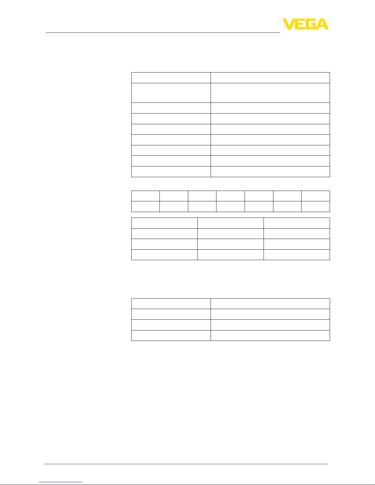
3.2 Safe state
Thesafestateofthecurrentoutputdependsonthesafetyfunction
andthecharacteristicssetonthesensor.
Character-
istics
Monitoring upper limit val-
ue
Monitoring lower limit value
4 … 20 mA Outputcurrent≥Switching
point
Outputcurrent≤Switching
point
20 … 4 mA Outputcurrent≤Switching
point
Outputcurrent≥Switching
point
Possiblefaultcurrents:
• ≤3.6mA("faillow")
• >21mA("failhigh")
3.3 Prerequisites for operation
• Themeasuringsystemshouldbeusedappropriatelytakingpres-
sure,temperature,densityandchemicalpropertiesofthemedium
intoaccount.Theapplication-speciclimitsmustbeobserved.
• Thespecicationsaccordingtotheoperatinginstructionsmanual,
particularlythecurrentloadontheoutputcircuits,mustbekept
withinthespeciedlimits
• Existingcommunicationinterfaces(e.g.HART,USB)arenotused
fortransmissionofthesafety-relevantmeasuredvalue
• The instructions in chapter "Safety-related characteristics", para-
graph"Supplementary information"mustbenoted
• Allpartsofthemeasuringchainmustcorrespondtotheplanned
"Safety Integrity Level (SIL)"
Safety function
Safety tolerance
Safe state
Output signals in case of
malfunction
Instructions and restric-
tions